EP0848231A1 - Unité de capteurs inertes - Google Patents
Unité de capteurs inertes Download PDFInfo
- Publication number
- EP0848231A1 EP0848231A1 EP98101587A EP98101587A EP0848231A1 EP 0848231 A1 EP0848231 A1 EP 0848231A1 EP 98101587 A EP98101587 A EP 98101587A EP 98101587 A EP98101587 A EP 98101587A EP 0848231 A1 EP0848231 A1 EP 0848231A1
- Authority
- EP
- European Patent Office
- Prior art keywords
- sensors
- inertial
- sensor unit
- inertial sensor
- unit according
- Prior art date
- Legal status (The legal status is an assumption and is not a legal conclusion. Google has not performed a legal analysis and makes no representation as to the accuracy of the status listed.)
- Granted
Links
Images


Classifications
-
- G—PHYSICS
- G01—MEASURING; TESTING
- G01C—MEASURING DISTANCES, LEVELS OR BEARINGS; SURVEYING; NAVIGATION; GYROSCOPIC INSTRUMENTS; PHOTOGRAMMETRY OR VIDEOGRAMMETRY
- G01C19/00—Gyroscopes; Turn-sensitive devices using vibrating masses; Turn-sensitive devices without moving masses; Measuring angular rate using gyroscopic effects
- G01C19/56—Turn-sensitive devices using vibrating masses, e.g. vibratory angular rate sensors based on Coriolis forces
-
- G—PHYSICS
- G01—MEASURING; TESTING
- G01C—MEASURING DISTANCES, LEVELS OR BEARINGS; SURVEYING; NAVIGATION; GYROSCOPIC INSTRUMENTS; PHOTOGRAMMETRY OR VIDEOGRAMMETRY
- G01C21/00—Navigation; Navigational instruments not provided for in groups G01C1/00 - G01C19/00
- G01C21/10—Navigation; Navigational instruments not provided for in groups G01C1/00 - G01C19/00 by using measurements of speed or acceleration
- G01C21/12—Navigation; Navigational instruments not provided for in groups G01C1/00 - G01C19/00 by using measurements of speed or acceleration executed aboard the object being navigated; Dead reckoning
- G01C21/16—Navigation; Navigational instruments not provided for in groups G01C1/00 - G01C19/00 by using measurements of speed or acceleration executed aboard the object being navigated; Dead reckoning by integrating acceleration or speed, i.e. inertial navigation
- G01C21/183—Compensation of inertial measurements, e.g. for temperature effects
Definitions
- the invention relates to an inertial sensor unit for measuring an inertial measured variable with a plurality of miniaturized, inertial sensors, the signals of the Sensors on common signal processing means for generating a measured variable reproducing output measurement signal is applied.
- the inertial measurement is an acceleration or a Understand the speed of rotation compared to the inertial space.
- Inertial sensors measure the acceleration or the yaw rate compared to the inertial one Room. Such inertial sensors can be used to create a platform in the room stabilize or measure the position or location of a wearer. To measure the Accelerometers are used for acceleration. The speed of rotation is determined by Gyroscope measured or by "laser gyroscope" based on the Sagnac effect. A big problem with such inertial sensors is that they have a very large measuring range of several orders of magnitude. It will high accuracy and freedom from drift are also required. Known inertial sensors of this Art are therefore extremely complex and correspondingly expensive components.
- Inertial sensors which contain miniaturized resonators Resonance behavior of the resonator is influenced by the inertial measurement variable.
- Such inertial sensors are e.g. Silicon or quartz inertial sensors.
- This Inertial sensors contain a micromechanically manufactured tuning fork made of silicon or a quartz crystal. In one designed as a rotational speed sensor
- This type of inertial sensor determines the frequency of the quartz crystal Coriolis force influenced.
- QRS accelerometer Inertial sensor
- QAS accelerometer Inertial sensor
- QAS accelerometer Inertial sensor
- QAS is a quartz crystal connected to a mass, so that with a inertial acceleration due to the inertial force a pressure on the quartz crystal is exercised. This pressure also changes the frequency of the quartz crystal. The Changes in frequency can be used as a measure of the respective inertial measurement will.
- inertial sensors are small, simple and inexpensive. But they don't meet that Inertial sensors for stabilization or navigation purposes in terms of dynamic range and accuracy.
- the inertial sensors only work at a time in a limited measuring range.
- the accuracy of the inertial sensors is limited.
- the Measurement characteristics of the inertial sensors are characterized by complex, non-linear, functional relationships between the inertial measurement quantity to be measured and the Output measurement signals. There are additional dependencies on others Influencing factors, such as temperature, must be taken into account.
- EP-A-0 567 938 describes a digital accelerometer with a A plurality of miniaturized, inertial sensors, the signals from the sensors on common signal processing means for generating a measured variable reproducing output measurement signal is applied.
- the micromechanical Sensors are micromechanically manufactured resilient arms with masses these arms are deflected when acceleration occurs. If the Acceleration is sufficiently large, the deflection of the arms makes contact closed. This contact is saved.
- a two-dimensional is preferred Arrangement of such micromechanical sensors is provided, the sensors in different resonance frequencies in one direction of the two-dimensional arrangement and have different sensitivities in the other direction, i.e. at contact different values of acceleration. In this way, a digital value of acceleration can be obtained.
- the invention has for its object a simple inertial sensor unit to create the ones provided for stabilization and navigation purposes Requirements are sufficient.
- the invention has for its object a simple structure To create an inertial sensor unit with a high dynamic range.
- the invention allows the use of inexpensive, small and lightweight miniaturized inertial sensors, e.g. Silicon or quartz inertial sensors. By multiplying such sensors and switching on the sensor signals A common signal processing can measure the entire inertial sensor unit to be raised to the requirements of inertial sensors for Stabilization and navigation purposes are provided.
- the multiplication of the miniaturized inertial sensors becomes possible because each one of these miniaturized Intertial sensors requires only a relatively small effort.
- laser gyro or Accelerometers become many miniaturized inertial sensors with fewer Goodness but also lower price, small space requirement and low weight used.
- the nonlinear characteristics of the possibly different inertial sensors can be taken into account in that the signal processing means a first have neural network, which is based on effective inertial parameters and assigned output measurement signals is trained.
- the signal processing means can have a second neural network, which is trained to detect sensor failures and the first neural Network from the second neural network in the sense of a reconfiguration of the sensors can be influenced.
- the result is a compact inertial sensor unit with high accuracy, large dynamic range and high redundancy, i.e. insensitivity to failure individual sensors.
- Embodiments of the invention are the subject of dependent claims.
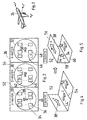
- the inertial sensor unit 10 contains along one Front edge N miniaturized inertial sensors 12.11, 12.21 ... 12.N1 in the form of Silicon or quartz inertial sensors.
- the inertial sensor 12.11 has a measuring range "1”
- the inertial sensor 12.21 has a measuring range "2" which corresponds to the measuring range "1" connects.
- the other inertial sensors indicated by dashed lines have further connected measuring ranges up to the inertial sensor 12.N1 with the Measuring range "N”.
- the measuring ranges "1" to N are consecutive Sub-areas of an extended measuring range.
- the inertial sensors 12.11 to 12.N1 respond to accelerations in the direction of arrow 14. You can also Be inertial sensors that operate at yaw rates around those determined by the arrow Address input axes.
- the miniaturized inertial sensors 12.11 to 12.N1 together cover an extended measuring range.
- Each of the miniaturized inertial sensors 12.11 to 12.N1 is provided in multiples. In addition to the inertial sensor 12.11, there are other ones that essentially match it and also in the measuring range "1" measuring inertial sensors 12.12 to 12.1M intended. In addition to the inertial sensor 12.21, there are the inertial sensors 12.22 to 12.2M etc. Except for the inertial sensor 12.N1, they essentially exist with it matching inertial sensors 12.N2 to 12.NM. To increase accuracy the mean value of the output signals of the inertial sensors 12.11 to 12.1M is formed. The mean values of the remaining “columns” of the “matrix” of Inertial sensors up to the inertial sensors 12.N1 to 12.NM are formed.
- the Inertial sensors 16 and 18 measure the components of the measured variable, e.g. Acceleration, perpendicular to each other and to the direction indicated by arrow 14 represented input axis.
- the input axis of the inertial sensor 16 is through a Arrow 20 and the input axis of the inertial sensor 18 are represented by an arrow 22.
- the inertial sensor unit 10 also contains a "matrix" of inertial sensors of the type of inertial sensor 18. Again, the inertial sensors of the "columns" different measuring ranges, the sub-ranges of an extended measuring range form.
- the "matrices" of the inertial sensors 16 and 18 are not shown in FIG. 1. It understands that the inertial sensors are not necessary, as shown, in a rectangular “Matrix" must be arranged.
- the inertial sensors are together with the associated circuit in one block integrated.
- inertial measurements accelerations, rotational speeds
- these axes are the longitudinal axis of the aircraft x F
- the transverse axis y F and the vertical axis z F. 3 to 6 show the structure of an inertial sensor unit, which allows inertial, vectorial measurement variables to be measured in three axes.
- FIG. 3 An elongated rectangular wafer carrier 26 is shown in FIG. 3. On the Wafer carrier 26 an “X wafer” is located next to one another in the longitudinal direction of wafer carrier 26. 28, a "Z-wafer” 30 and a "Y-wafer” 32. A first is on the X-wafer 28 Group 34 of miniaturized inertial sensors. Group 34 of Inertial sensors consist, for example, of silicon or quartz rotation speed sensors (QRSs) 36. The rotational speed sensors 36 are in a matrix of rows and columns is formed on the X-wafer. The entrance axes of the rotation speed sensors 36 are all in the direction of the arrow 38.
- QRSs quartz rotation speed sensors
- the rotational speed sensors 36 on the wafer 28 can all in the be designed to be essentially the same. However, they are advantageous rotational speed sensors 36 arranged in a row of the matrix as in FIG 1 designed for different measuring ranges, the sub-ranges of an extended measuring range.
- the rotation speed sensors 36 arranged in a column of the matrix are each essentially coinciding with each other. It can also be on the X wafer 28 additional accelerometers may be formed. Also their input or Sensitivity axes are in the direction of arrow 38.
- the Z wafer 30 with the second group 42 is made of silicon or silicon Quartz rotational speed sensors 40 are formed.
- the input or Sensitivity axes of the rotational speed sensors 40 are all in Direction of arrow 44, that is to say in FIG. 3 perpendicular to that indicated by arrow 38 represented input or sensitivity axes of the Rotational speed sensors 36 of the first group 34.
- the Y wafer 32 has a third group 46 of silicon or quartz rotational speed sensors 48 on.
- the rotational speed sensors 48 of the third Group 46 are arranged in a matrix in the same way as that Rotational speed sensors of the second group 42.
- the input or Sensitivity axes of the rotational speed sensors 48 lie in the direction of Arrow 50 parallel in Fig. 3 to the input or sensitivity axes of the quartz speed sensors 40 of the second group 42.
- the elongated rectangular wafer carrier 26 is angled along the folded edges 52 and 54 in the manner shown in FIGS. 4 and 5.
- the wafer carrier 26 is angled by 90 ° between the wafers 28 and 30 and groups 34 and 42 along the folded edge 52. This is shown in Fig. 4.
- a cross-sectionally U-shaped structure is formed with three sections 56, 58, 60 of the weapon carrier 26. From FIG. 5 it can be seen that the directions of the input or sensitivity axes of the Inertial sensors 36, 40 and 48, as represented by arrows 38, 44 and 50 in FIGS. 4 and 5, are mutually orthogonal. They can be aligned in an aircraft 24 in the direction of the axes x F , z F or y F.
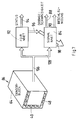
- Fig. 6 shows the design of the inertial sensor unit.
- a mounting plate is designated.
- the sections sit on the mounting plate 62 56, 58 and 60 of the wafer carrier 26. Of which the section 60 lies on the mounting plate 62 on.
- the sections 58 and 56 form the rear wall or top of a rectangular Housing 64.
- Housing 64 is on one end face through a housing wall 66 closed.
- the housing 64 is open on the opposite end face.
- On the Front, opposite section 58, the housing 64 is detachable Cover plate 68 closed.
- the housing 64 is inserted into the housing from the open end Microelectronic module 70 inserted.
- the microelectronic module 70 contains an interface 72, readout electronics 74, signal processing circuit 76, power supply 78, and wiring and Connections 80.
- the microelectronic module 70 is connected to the inertial sensors 36, 40 and 48 forming wafers 28, 30 and 32, respectively, are connected via a ribbon cable 82.
- Miniaturized inertial sensors of the type present here such as silicon or quartz inertial sensors provide very strong nonlinear output signals in the form of frequencies.
- this is achieved by means of a neural network 84, the “signal NNET”, which forms part of signal processing 76 in FIG. 6.
- the neural network 84 receives the signals from all miniaturized inertial sensors 36, 40, 48.
- the neural network can continue to be acted upon by signals, the other Influencing factors, e.g. Temperatures.
- the neural network 84 is trained.
- the inertial sensor unit in the form of a sensor block 86 is different inertial measurements and e.g. Subject to temperatures.
- the received Output signals are compared with "setpoints" of a desired characteristic.
- the weights of the neural network 84 are based on this comparison changed according to a given algorithm.
- this neural network 84 need not be programmed. It it is therefore not necessary to model the effects described above. Rather learn the neural network in a calibration phase the mathematical relationships between the functionally involved variables.
- the sensor block 86 contains Speed sensors and acceleration sensors.
- the signals from all sensors are connected to the neural network 84.
- the neural network 84 delivers on one Output 88 an output signal representing the rotational speeds and on an output 90 which represents the accelerations (in three axes) Output signal.
- the inertial sensors in the "columns" of each matrix are essentially each consistent. There are therefore several in the “rows” of the matrix matching sets of different inertial sensors are provided.
- the Information is thus delivered redundantly. Except for increasing accuracy this redundancy can also be exploited by averaging, failures to recognize such inertial sensors and to compensate them by reconfiguration.
- a further neural network 92 an "FDIR-NNET" (network for error detection, identification and sensor reconfiguration).
- the neural network 92 is in the manner of DE-A-42 44 mentioned above 014 built.
- the error-detecting neural network 92 receives the same signals supplied by the inertial sensors 36, 40, 48 such as the signal-processing, neural Network 84.
- Fault-detecting neural network 92 is trained to do so in the event of a failure an inertial sensor or a set of inertial sensors at an output 94 one To deliver "status” i.e. a signal vector that indicates which inertial sensor the Failure occurred.
- the "status" vector is also, as indicated by an output 96, as further input connected to the neural network 84 and influences it neural network 84. This is symbolized by an arrow 98.
- the signal processing neural network 84 is also with sensor signals switched off and corresponding status vectors trains to respond to failure of inertial sensors and such failures the formation of the rotational speed and acceleration signals at the outputs 88 or 90 to be taken into account.
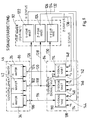
- FIG 8 shows the structure of the neural networks 84 and 92.
- the groups 34, 42 and 46 of inertial sensors 36, 40 arranged on the wafer 26 and 48 deliver measurement signals at outputs 100, 102 and 104 separately for the Components in the direction of the X axis, the Z axis or the Y axis.
- the exits 100, 102 and 104 are represented in FIG. 7 by a bus 106.
- the outputs are with the flat cable 82 of FIG. 6 connected.
- the outputs 100, 102, 104 are once with the signal processing neural network 84, as shown in FIG. 7 by a bus 108.
- the neural network 84 in turn contains three separate neural networks 110, 112 and 114 for the x components, the y components and the z components of the vectorial parameters.
- the actually from a plurality of signal outputs The output 100 formed is via a connection 116 to the neural network 110 connected.
- the output 102 is connected to the neural network 112 via a connection 118 connected.
- the output 104 is connected to the neural network 114 via a connection 120 connected.
- the error-detecting neural network 92 is also made up of three separate neural ones Networks 122, 124 and 126 constructed for the inertial sensors 36, 40 and 48, respectively.
- the exit 100 is connected to the neural network 122 via a connection 126.
- the exit 102 is connected to neural network 124 via a connection 128.
- the exit 104 is connected to the neural network 126 via a connection 130.
- Through the neural networks 122, 124 and 126 become status vectors for the inertial sensors 36, 40 or 48 generated. These status vectors are over connections 132, 134 and 136, respectively as further input variables to the associated signal processing neural networks 110, 112 and 114, respectively. Connections 132, 134 and 136 correspond to output 96 of FIG. 7.
- Each of the neural networks 110, 112 and 114 delivers the relevant component ⁇ x , ⁇ z , ⁇ y of the rotational speed to a first output 138, 140 and 142 and the relevant component a x to a second output 144, 146 and 148 , a z or y y of the acceleration.
- the outputs 138, 140 and 142 of FIG. 8 are combined in the output 88 of FIG. 7.
- the individual components of the Measured quantities processed independently of one another.
- micromechanical inertial sensors can be tuning fork gyroscopes made of silicon or polysilicon.
- Accelerometers can be micromechanically like a pendulum accelerometer be constructed.
- Other miniaturized resonators like Micro-optic gyroscopes (MOGs) can be considered for this application.
Landscapes
- Engineering & Computer Science (AREA)
- Radar, Positioning & Navigation (AREA)
- Remote Sensing (AREA)
- Physics & Mathematics (AREA)
- General Physics & Mathematics (AREA)
- Automation & Control Theory (AREA)
- Gyroscopes (AREA)
- Navigation (AREA)
Applications Claiming Priority (3)
| Application Number | Priority Date | Filing Date | Title |
|---|---|---|---|
| DE4419925 | 1994-06-08 | ||
| DE4419925A DE4419925A1 (de) | 1994-06-08 | 1994-06-08 | Inertialsensor-Einheit |
| EP95710013A EP0686830B1 (fr) | 1994-06-08 | 1995-05-23 | Unité capteur inertiel |
Related Parent Applications (1)
| Application Number | Title | Priority Date | Filing Date |
|---|---|---|---|
| EP95710013A Division EP0686830B1 (fr) | 1994-06-08 | 1995-05-23 | Unité capteur inertiel |
Publications (2)
| Publication Number | Publication Date |
|---|---|
| EP0848231A1 true EP0848231A1 (fr) | 1998-06-17 |
| EP0848231B1 EP0848231B1 (fr) | 2002-04-10 |
Family
ID=6520025
Family Applications (2)
| Application Number | Title | Priority Date | Filing Date |
|---|---|---|---|
| EP95710013A Expired - Lifetime EP0686830B1 (fr) | 1994-06-08 | 1995-05-23 | Unité capteur inertiel |
| EP98101587A Expired - Lifetime EP0848231B1 (fr) | 1994-06-08 | 1995-05-23 | Unité de capteurs inertes |
Family Applications Before (1)
| Application Number | Title | Priority Date | Filing Date |
|---|---|---|---|
| EP95710013A Expired - Lifetime EP0686830B1 (fr) | 1994-06-08 | 1995-05-23 | Unité capteur inertiel |
Country Status (2)
| Country | Link |
|---|---|
| EP (2) | EP0686830B1 (fr) |
| DE (3) | DE4419925A1 (fr) |
Cited By (8)
| Publication number | Priority date | Publication date | Assignee | Title |
|---|---|---|---|---|
| WO2001036913A1 (fr) * | 1999-11-18 | 2001-05-25 | Honeywell Inc. | Systeme de mesures inertielles |
| WO2006121583A1 (fr) * | 2005-05-09 | 2006-11-16 | Northrop Grumman Corporation | Ameliorations apportees a la determination de caracteristiques environnementales |
| CN1330933C (zh) * | 2006-06-27 | 2007-08-08 | 北京航空航天大学 | 一种基于神经网络的开环光纤陀螺输出误差补偿方法 |
| EP1166147B1 (fr) * | 1999-05-28 | 2009-04-08 | Fisher-Tortolano Systems Limited | Appareil et procede de navigation |
| CN100538276C (zh) * | 2007-11-16 | 2009-09-09 | 北京航空航天大学 | 一种基于集成神经网络的微小卫星用mems陀螺仪误差补偿方法 |
| CN103411628A (zh) * | 2013-08-14 | 2013-11-27 | 西北工业大学 | 一种mems陀螺仪随机漂移误差的处理方法 |
| US11348274B2 (en) | 2017-01-23 | 2022-05-31 | Oxford University Innovation Limited | Determining the location of a mobile device |
| US11436749B2 (en) | 2017-01-23 | 2022-09-06 | Oxford University Innovation Limited | Determining the location of a mobile device |
Families Citing this family (10)
| Publication number | Priority date | Publication date | Assignee | Title |
|---|---|---|---|---|
| WO1999003043A2 (fr) * | 1997-07-09 | 1999-01-21 | Siemens Aktiengesellschaft | Procede et structure pour la modelisation neuronale d'un systeme dynamique dans un ordinateur |
| DE19857894A1 (de) | 1998-12-15 | 2000-06-21 | Bodenseewerk Geraetetech | Flugkörper |
| US6701788B2 (en) * | 2001-07-31 | 2004-03-09 | Kelsey-Hayes Company | Multiple output inertial sensing device |
| DE10254163A1 (de) * | 2002-11-21 | 2004-06-03 | Eads Deutschland Gmbh | Mikromechanischer Drehratensensor |
| EP1872087A4 (fr) * | 2005-04-19 | 2012-10-17 | Jaymart Sensors Llc | Centrale inertielle miniaturisee et procedes associes |
| IL195104A (en) * | 2008-11-04 | 2013-07-31 | Dekel Tzidon | A device and method for integrating @ @ inertial @ @ measurements from cluster @ sensors |
| FR2966587B1 (fr) * | 2010-10-22 | 2012-12-21 | Sagem Defense Securite | Dispositif inertiel comportant des capteurs inertiels de precisions differentes |
| IL249050B (en) | 2016-11-17 | 2018-03-29 | Elbit Systems Ltd | Self-calibrating inertial measurement method and system |
| DE102017006611A1 (de) * | 2017-07-12 | 2019-01-17 | Mbda Deutschland Gmbh | Inertialsensorsystem für Flugkörper und Verfahren zur flugphasenabhängigen Intertialsensormessung |
| JP7491140B2 (ja) * | 2020-08-24 | 2024-05-28 | セイコーエプソン株式会社 | 慣性センサー装置、及び慣性計測ユニット |
Citations (3)
| Publication number | Priority date | Publication date | Assignee | Title |
|---|---|---|---|---|
| US5001933A (en) * | 1989-12-26 | 1991-03-26 | The United States Of America As Represented By The Secretary Of The Army | Micromechanical vibration sensor |
| DE9113744U1 (de) * | 1991-11-05 | 1992-01-16 | SMT & Hybrid GmbH, O-8012 Dresden | Dreidimensionaler mikromechanischer Beschleunigungssensor mit integrierter Elektronik |
| EP0567938A1 (fr) * | 1992-04-30 | 1993-11-03 | Texas Instruments Incorporated | Accéléromètre numérique |
Family Cites Families (1)
| Publication number | Priority date | Publication date | Assignee | Title |
|---|---|---|---|---|
| DE4244014A1 (de) | 1992-12-24 | 1994-07-07 | Bodenseewerk Geraetetech | Verfahren zum Erkennen und Identifizieren von Fehlern an Sensoren |
-
1994
- 1994-06-08 DE DE4419925A patent/DE4419925A1/de not_active Withdrawn
-
1995
- 1995-05-23 DE DE59510163T patent/DE59510163D1/de not_active Expired - Fee Related
- 1995-05-23 DE DE59503052T patent/DE59503052D1/de not_active Expired - Fee Related
- 1995-05-23 EP EP95710013A patent/EP0686830B1/fr not_active Expired - Lifetime
- 1995-05-23 EP EP98101587A patent/EP0848231B1/fr not_active Expired - Lifetime
Patent Citations (3)
| Publication number | Priority date | Publication date | Assignee | Title |
|---|---|---|---|---|
| US5001933A (en) * | 1989-12-26 | 1991-03-26 | The United States Of America As Represented By The Secretary Of The Army | Micromechanical vibration sensor |
| DE9113744U1 (de) * | 1991-11-05 | 1992-01-16 | SMT & Hybrid GmbH, O-8012 Dresden | Dreidimensionaler mikromechanischer Beschleunigungssensor mit integrierter Elektronik |
| EP0567938A1 (fr) * | 1992-04-30 | 1993-11-03 | Texas Instruments Incorporated | Accéléromètre numérique |
Non-Patent Citations (1)
| Title |
|---|
| GUSTAFSON S C ET AL: "Locally linear neural networks for aerospace navigation systems", MACHINE INTELLIGENCE FOR AEROSPACE ELECTRONICS SYSTEMS. PAPERS PRESENTED AT THE AVIONICS PANEL SYMPOSIUM (AGARD-CP-499), LISBON, PORTUGAL, 13-16 MAY 1991, 1991, NEUILLY SUR SEINE, FRANCE, AGARD, FRANCE, pages 15/1 - 8, XP002058923 * |
Cited By (10)
| Publication number | Priority date | Publication date | Assignee | Title |
|---|---|---|---|---|
| EP1166147B1 (fr) * | 1999-05-28 | 2009-04-08 | Fisher-Tortolano Systems Limited | Appareil et procede de navigation |
| WO2001036913A1 (fr) * | 1999-11-18 | 2001-05-25 | Honeywell Inc. | Systeme de mesures inertielles |
| WO2006121583A1 (fr) * | 2005-05-09 | 2006-11-16 | Northrop Grumman Corporation | Ameliorations apportees a la determination de caracteristiques environnementales |
| US7650238B2 (en) | 2005-05-09 | 2010-01-19 | Northrop Grumman Corporation | Environmental characteristic determination |
| CN1330933C (zh) * | 2006-06-27 | 2007-08-08 | 北京航空航天大学 | 一种基于神经网络的开环光纤陀螺输出误差补偿方法 |
| CN100538276C (zh) * | 2007-11-16 | 2009-09-09 | 北京航空航天大学 | 一种基于集成神经网络的微小卫星用mems陀螺仪误差补偿方法 |
| CN103411628A (zh) * | 2013-08-14 | 2013-11-27 | 西北工业大学 | 一种mems陀螺仪随机漂移误差的处理方法 |
| CN103411628B (zh) * | 2013-08-14 | 2016-01-13 | 西北工业大学 | 一种mems陀螺仪随机漂移误差的处理方法 |
| US11348274B2 (en) | 2017-01-23 | 2022-05-31 | Oxford University Innovation Limited | Determining the location of a mobile device |
| US11436749B2 (en) | 2017-01-23 | 2022-09-06 | Oxford University Innovation Limited | Determining the location of a mobile device |
Also Published As
| Publication number | Publication date |
|---|---|
| DE59503052D1 (de) | 1998-09-10 |
| DE4419925A1 (de) | 1995-12-14 |
| DE59510163D1 (de) | 2002-05-16 |
| EP0686830B1 (fr) | 1998-08-05 |
| EP0848231B1 (fr) | 2002-04-10 |
| EP0686830A1 (fr) | 1995-12-13 |
Similar Documents
| Publication | Publication Date | Title |
|---|---|---|
| EP0686830B1 (fr) | Unité capteur inertiel | |
| DE3433189C2 (de) | Vorrichtung mit Beschleunigungsmessern und einer Trägheitsplattform sowie Trägheitsplattform für eine solche Vorrichtung | |
| DE19654304B4 (de) | Mikrogyroskop | |
| DE69904551T2 (de) | Drehgeschwindigkeitssensorvorrichtung | |
| DE69609434T2 (de) | Kompensationsvorrichtung für mikromechanische Sensoren | |
| EP2547984B1 (fr) | Procédé de régulation découplée de la quadrature et de la fréquence de résonance d'un gyroscope micromécanique | |
| DE69704408T2 (de) | Drehgeschwindigkeitserfassungsvorrichtung | |
| DE69320207T2 (de) | Dreiachsenmessaufnehmer für drehgeschwindigkeit und beschleunigung | |
| DE19642893B4 (de) | Schwingungskonstruktion | |
| DE2920194C2 (fr) | ||
| DE69008165T2 (de) | Fühlelement für ein gyroskop. | |
| DE69307587T2 (de) | Kreiselkompass | |
| DE69733301T2 (de) | Scullingeffektkompensation in Strapdown-Inertialnavigationssystemen | |
| DE102005012155B4 (de) | Vibrations-Winkelgeschwindigkeitssensor | |
| DE19620831A1 (de) | Stimmgabelkreisel | |
| DE69615468T2 (de) | Vorrichtung zum Messen einer Winkelgeschwindigkeit | |
| DE19654303B4 (de) | Mikrogyroskop | |
| DE3033280C2 (de) | Kurs-Lage-Referenzgerät | |
| DE69517766T2 (de) | Richtungs-Sensor und Richtungs-Entfernungs-Sensor | |
| DE69404977T2 (de) | Temperaturkorrigierter integrierender analog-digital-wandler | |
| DE69310799T2 (de) | Vibrator mit abgeglichenen Kantenbereichen | |
| DE4431232C2 (de) | Integrierbares Feder-Masse-System | |
| DE3432150C2 (fr) | ||
| DE3539552C2 (de) | Winkelgeschwindigkeitssensor, insbesondere für die Flugzeugnavigation | |
| DE29508525U1 (de) | Inertialsensor-Einheit |
Legal Events
| Date | Code | Title | Description |
|---|---|---|---|
| PUAI | Public reference made under article 153(3) epc to a published international application that has entered the european phase |
Free format text: ORIGINAL CODE: 0009012 |
|
| AC | Divisional application: reference to earlier application |
Ref document number: 686830 Country of ref document: EP |
|
| AK | Designated contracting states |
Kind code of ref document: A1 Designated state(s): DE FR GB SE |
|
| 17P | Request for examination filed |
Effective date: 19980513 |
|
| 17Q | First examination report despatched |
Effective date: 19990713 |
|
| GRAG | Despatch of communication of intention to grant |
Free format text: ORIGINAL CODE: EPIDOS AGRA |
|
| GRAG | Despatch of communication of intention to grant |
Free format text: ORIGINAL CODE: EPIDOS AGRA |
|
| GRAH | Despatch of communication of intention to grant a patent |
Free format text: ORIGINAL CODE: EPIDOS IGRA |
|
| REG | Reference to a national code |
Ref country code: GB Ref legal event code: IF02 |
|
| GRAH | Despatch of communication of intention to grant a patent |
Free format text: ORIGINAL CODE: EPIDOS IGRA |
|
| GRAA | (expected) grant |
Free format text: ORIGINAL CODE: 0009210 |
|
| AC | Divisional application: reference to earlier application |
Ref document number: 686830 Country of ref document: EP |
|
| AK | Designated contracting states |
Kind code of ref document: B1 Designated state(s): DE FR GB SE |
|
| REF | Corresponds to: |
Ref document number: 59510163 Country of ref document: DE Date of ref document: 20020516 |
|
| GBT | Gb: translation of ep patent filed (gb section 77(6)(a)/1977) |
Effective date: 20020703 |
|
| ET | Fr: translation filed | ||
| PLBE | No opposition filed within time limit |
Free format text: ORIGINAL CODE: 0009261 |
|
| STAA | Information on the status of an ep patent application or granted ep patent |
Free format text: STATUS: NO OPPOSITION FILED WITHIN TIME LIMIT |
|
| 26N | No opposition filed |
Effective date: 20030113 |
|
| PGFP | Annual fee paid to national office [announced via postgrant information from national office to epo] |
Ref country code: SE Payment date: 20080529 Year of fee payment: 14 Ref country code: DE Payment date: 20080730 Year of fee payment: 14 |
|
| PGFP | Annual fee paid to national office [announced via postgrant information from national office to epo] |
Ref country code: FR Payment date: 20080530 Year of fee payment: 14 |
|
| PGFP | Annual fee paid to national office [announced via postgrant information from national office to epo] |
Ref country code: GB Payment date: 20080602 Year of fee payment: 14 |
|
| GBPC | Gb: european patent ceased through non-payment of renewal fee |
Effective date: 20090523 |
|
| REG | Reference to a national code |
Ref country code: FR Ref legal event code: ST Effective date: 20100129 |
|
| PG25 | Lapsed in a contracting state [announced via postgrant information from national office to epo] |
Ref country code: FR Free format text: LAPSE BECAUSE OF NON-PAYMENT OF DUE FEES Effective date: 20090602 |
|
| PG25 | Lapsed in a contracting state [announced via postgrant information from national office to epo] |
Ref country code: GB Free format text: LAPSE BECAUSE OF NON-PAYMENT OF DUE FEES Effective date: 20090523 |
|
| PG25 | Lapsed in a contracting state [announced via postgrant information from national office to epo] |
Ref country code: DE Free format text: LAPSE BECAUSE OF NON-PAYMENT OF DUE FEES Effective date: 20091201 |
|
| PG25 | Lapsed in a contracting state [announced via postgrant information from national office to epo] |
Ref country code: SE Free format text: LAPSE BECAUSE OF NON-PAYMENT OF DUE FEES Effective date: 20090524 |