EP0848344B2 - Vorrichtung zum Abtasten eines sich auf einem bewegenden Artikel befindlichen optischen Kodes und Verfahren zum Abtasten eines solchen optischen Kodes mittels dieser Abtastvorrichtung - Google Patents
Vorrichtung zum Abtasten eines sich auf einem bewegenden Artikel befindlichen optischen Kodes und Verfahren zum Abtasten eines solchen optischen Kodes mittels dieser Abtastvorrichtung Download PDFInfo
- Publication number
- EP0848344B2 EP0848344B2 EP97203806A EP97203806A EP0848344B2 EP 0848344 B2 EP0848344 B2 EP 0848344B2 EP 97203806 A EP97203806 A EP 97203806A EP 97203806 A EP97203806 A EP 97203806A EP 0848344 B2 EP0848344 B2 EP 0848344B2
- Authority
- EP
- European Patent Office
- Prior art keywords
- prefixed
- angle
- light beam
- scanning
- reader according
- Prior art date
- Legal status (The legal status is an assumption and is not a legal conclusion. Google has not performed a legal analysis and makes no representation as to the accuracy of the status listed.)
- Expired - Lifetime
Links
Images
Classifications
-
- G—PHYSICS
- G06—COMPUTING OR CALCULATING; COUNTING
- G06K—GRAPHICAL DATA READING; PRESENTATION OF DATA; RECORD CARRIERS; HANDLING RECORD CARRIERS
- G06K7/00—Methods or arrangements for sensing record carriers, e.g. for reading patterns
- G06K7/10—Methods or arrangements for sensing record carriers, e.g. for reading patterns by electromagnetic radiation, e.g. optical sensing; by corpuscular radiation
- G06K7/10544—Methods or arrangements for sensing record carriers, e.g. for reading patterns by electromagnetic radiation, e.g. optical sensing; by corpuscular radiation by scanning of the records by radiation in the optical part of the electromagnetic spectrum
- G06K7/10821—Methods or arrangements for sensing record carriers, e.g. for reading patterns by electromagnetic radiation, e.g. optical sensing; by corpuscular radiation by scanning of the records by radiation in the optical part of the electromagnetic spectrum further details of bar or optical code scanning devices
- G06K7/10861—Methods or arrangements for sensing record carriers, e.g. for reading patterns by electromagnetic radiation, e.g. optical sensing; by corpuscular radiation by scanning of the records by radiation in the optical part of the electromagnetic spectrum further details of bar or optical code scanning devices sensing of data fields affixed to objects or articles, e.g. coded labels
-
- G—PHYSICS
- G06—COMPUTING OR CALCULATING; COUNTING
- G06K—GRAPHICAL DATA READING; PRESENTATION OF DATA; RECORD CARRIERS; HANDLING RECORD CARRIERS
- G06K7/00—Methods or arrangements for sensing record carriers, e.g. for reading patterns
- G06K7/10—Methods or arrangements for sensing record carriers, e.g. for reading patterns by electromagnetic radiation, e.g. optical sensing; by corpuscular radiation
- G06K7/10544—Methods or arrangements for sensing record carriers, e.g. for reading patterns by electromagnetic radiation, e.g. optical sensing; by corpuscular radiation by scanning of the records by radiation in the optical part of the electromagnetic spectrum
- G06K7/10554—Moving beam scanning
- G06K7/10594—Beam path
- G06K7/10603—Basic scanning using moving elements
- G06K7/10613—Basic scanning using moving elements by rotation, e.g. polygon
- G06K7/10623—Constructional details
-
- G—PHYSICS
- G06—COMPUTING OR CALCULATING; COUNTING
- G06K—GRAPHICAL DATA READING; PRESENTATION OF DATA; RECORD CARRIERS; HANDLING RECORD CARRIERS
- G06K7/00—Methods or arrangements for sensing record carriers, e.g. for reading patterns
- G06K7/10—Methods or arrangements for sensing record carriers, e.g. for reading patterns by electromagnetic radiation, e.g. optical sensing; by corpuscular radiation
- G06K7/10544—Methods or arrangements for sensing record carriers, e.g. for reading patterns by electromagnetic radiation, e.g. optical sensing; by corpuscular radiation by scanning of the records by radiation in the optical part of the electromagnetic spectrum
- G06K7/10554—Moving beam scanning
- G06K7/10594—Beam path
- G06K7/10603—Basic scanning using moving elements
- G06K7/10673—Parallel lines
Definitions
- the present invention relates to a scanning reader of an optical code placed on an article in movement and a method of scanning said optical code by means of said reader.
- optical code is intended to mean a set of graphic markings (placed on a label or directly on a product or on any other support) by means of which a piece of information is coded as a sequence of white areas and black areas or of variously coloured areas, arranged according to one or more directions. Examples of such codes are the bar codes, the two-dimensional codes, the colour codes and the like.
- a scanning reader of an optical code placed on an article in movement comprises a source of light capable of generating a beam of coherent light and suitable optical components capable of focusing the light beam on the code, forming a scanning line.
- the light diffused by the optical code consisting of a series of impulses, is directed to a photodetector that emits electrical signals representative of the detected light.
- the electrical signals are decoded in an electrical or electronic circuit that provides data capable of describing the optical code.
- the optical code is of the bar type, as is commonly the case, in order to read it correctly, the light beam is focused on the code so that the projection of its cross-section on the code has precise dimensions, determined by the thickness of the bars of the code. In fact, the reading of the code would be incorrect if the cross-section of the light beam were to cover more than two bars.
- US 5 392 150 discloses a hand-held portable bar code reader comprising a laser beam source, a crystal resonant scanner, a photodetector and a concave mirror.
- the concave mirror and the resonant scanner are integrally coupled to each other and can be angularly moved by a step motor about a horizontal axis. When they are angularly moved, the bar code reader can scan a surface in a raster scanning mode.
- EP 0 396 485 discloses an optical bar code scanner with an asymmetrical rotating deflector wich deflect the light beam generated by a light source and causes it to focus at different focal points outside a scanning window of the scanner.
- the article In a number of cases the article is transported by a conveyor belt and the reader is located along the path of the article so as to be able to read the optical code that is applied in a random position on one of its walls. If the optical code is on a side wall, substantially parallel to the direction of movement of the article, the optical code reader is placed in front of such wall.
- the beam of scanning light has a direction that is substantially orthogonal to the wall on which there is the optical code and, whatever the position of the optical code with respect to the wall, on the top, on the bottom, in the centre or on the sides, the reading does not exhibit any problems.
- the optical code is placed on afront or rear wall of the article, substantially orthogonal to the direction of movement
- the reader is placed above the conveyor belt and, thus, above the front or rear wall on which there is the code and the article, with its movement, gets closer to it or moves away from it.
- the beam of scanning light has a direction oblique with respectto the optical code and it is difficult to make a sufficient number of useful scans while the article is in the range of depth of the light beam that, generally, is fairly narrow.
- JP 55 092972-A discloses a method to read a bar code label stuck to a flank or top surface of a commodity conveyed on a conveyor.
- the bar code label is read out by a bar-code reader provided in slanting direction at a fixed angle of 45 degree from the commodity to a line perpendicular to the top surface or to the flank of the commodity.
- EP 0 650 134 A2 discloses a scanner arranged outside the movement path of an object and directed towards the front surface, seen in the movement direction, of the object. The scanner generates a scanning light beam moving line by line over a surface of the object. An advancing means for the displacement of the scanning line is provided in such a way that the distance of the scanner from the scanning line on the surface of the object stays at least essentially the same.
- said generation means form more than two beams of light, for example three or four beams.
- the number of scans per second executed by said beams of light are not the same.
- the number of scans per second executed by said beams of light is such that the number of useful scans on said code is substantially constant.
- the ratio between the number of scans per unit of time of each light beam is inversely proportional to the angle of the plane containing the same beam with respect to the front wall.
- said generation means comprise at least one source of a light beam and deflection means of said beam.
- the deflection means comprise a polygonal rotor having mirror faces.
- the polygonal rotor comprises at least one prefixed number of mirrors inclined by a first prefixed angle ⁇ 1 with respect to the axis of rotation of said rotor and a second prefixed number of mirrors inclined by a second prefixed angle ⁇ 2 with respect to the axis of rotation of said rotor.
- said polygonal rotor comprises a first prefixed number of mirrors inclined by a first prefixed angle with respect to the axis of rotation of said rotor, a second prefixed number of mirrors inclined by a second prefixed angle with respect to the axis of rotation of said rotor and a third prefixed number of mirrors inclined by a third prefixed angle with respect to the axis of rotation of said rotor.
- said polygonal rotor comprises a first prefixed number of mirrors inclined by a first prefixed angle with respect to the axis of rotation of said rotor, a second prefixed number of mirrors inclined by a second prefixed angle with respect to the axis of rotation of said rotor, a third prefixed number of mirrors inclined by a third prefixed angle with respect to the axis of rotation of said rotor and a fourth prefixed number of mirrors inclined by a fourth prefixed angle with respect to the axis of rotation of said rotor.
- angles ⁇ 1 and ⁇ 2 of said mirrors are supplementary.
- said angle ⁇ 1 ranges from +5° to +15° and even more preferably from +7° to +9°.
- the values of ⁇ 2 are supplementary to those of ⁇ 1 .
- said polygonal rotor has ten mirror faces with a sequence of the mirrors of: 3 -1 - 2 -1 - 2 - 1.
- the invention has the advantage of increasing the depth of the field for reading the optical code, that is to say the distance between maximum and minimum height of the label with respect to the wall of the article, and it allows accurate readings of the optical to be taken whatever its position may be on the wall suitably selecting the angles of inclination of the planes containing the beams of light.
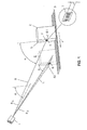
- Fig. 1 there is represented schematically a scanning reader 1 and an article 2 placed on a conveyor belt 3 that makes it move forward in the direction of the reader 1 (arrow 4).
- a vertical front wall 5 of the article 2 there is a label 6 on which an optical bar code 7 is printed.
- the reader 1 emits a light beam 8 ⁇ having an axis 9 that lies on a plane inclined by an angle ⁇ with respect to the wall 5.
- the beam 8 ⁇ executes a scanning line 81 substantially horizontal and orthogonal to the bar code 7, that allows an upper area of the wall 5 to be explored.
- the light beam 8 ⁇ is deflected sharply downward and forms a light beam 8 ⁇ that has axis 11 lying on a plane inclined by an angle ⁇ with respect to the wall 5.
- the beam 8 with inclination ⁇ executes a scanning line 82 on the wall 5 also having a substantially horizontal direction that allows a lower area of the wall 5 to be explored.
- Suitable deflection and scanning means of the reader 1, that will be described later, project the light beam 8 ⁇ with a scanning frequency v ⁇ that is inversely proportional to the angle of inclination ⁇ .
- the abovementioned deflection and scanning means project the same light beam 8 ⁇ with a scanning frequency v ⁇ that is inversely proportional to the angle of inclination ⁇ .
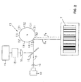
- a reader 1 comprising a laser source 10 of a light beam 8 and optical components 12 capable of focusing the beam 8 at a prefixed distance with a preselected depth of field.
- the light beam 8 is emitted by the source 10 with a preselected initial inclination ⁇ with respect to the vertical wall 5 and it is directed on a polygonal rotor with mirrors 13, rotating at preselected speed, capable of deflecting the beam 8 according to two angles ⁇ and ⁇ and giving rise first to the beam 8 ⁇ and then to the beam 8 ⁇ , forming the scanning lines 81 and 82.
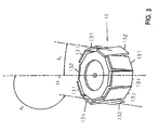
- the rotor 13, as shown in Fig. 3, is endowed with ten faces formed by mirrors having a preselected inclination with respect to the axis of rotation 14.
- the ten mirror faces have successive inclinations ⁇ 1 and ⁇ 2 according to the sequence 3-1-2-1-2-1, that is to say three mirror faces 131 inclined by ⁇ 1 , are followed by one mirror face 132 inclined by ⁇ 2 ; the latter is followed by two faces 131 inclined by ⁇ 1 , then there is one mirror face 132 inclined by ⁇ 2 , after this two faces 131 inclined by ⁇ 1 and lastly one mirror face 132 inclined by ⁇ 2 .
- the angle ⁇ 1 ranges from +5° to +15° and, preferably, from +7° to +9°.
- the values of ⁇ 2 are supplementary to those of ⁇ 1 .
- the beam 8 is deflected by the rotor 13 toward the wall 5 of the article 2 and, due to the effect of the rotation of the rotor 13 and of the different inclinations of its faces 131 and 132, it assumes the two inclinations ⁇ and ⁇ where it forms the two scanning lines 81 and 82.
- the light incident on the bar code 7 is diffused back toward the rotor 13 that deflects it toward a beam splitter 15. From the beam splitter 15 the light is directed toward an optical system 16 that focuses it on a photodetector 18.
- the photodetector 18 emits an electrical signal representative of the optical signal that is sent to a microprocessor unit of digitalisation and then of decoding 19. From the decoding unit 19 a signal is emitted corresponding to the image of the bar code scanned by the beam 8 ⁇ or by the beam 8 ⁇ .
- a rotor with mirrors 13 is used having a preselected number of faces inclined by a third angle ⁇ 3 and possibly by a fourth angle ⁇ 4 with respect to the axis of rotation 14, suitably selecting the sequence of the mirrors.
- a mirror oscillating in jerks is used that moves between two or more positions that allow the desired angles of deflection of the light beam generated by the laser source to be obtained.
- the same laser source is driven to oscillate in jerks between two or more positions that allow the desired angles of deflection of the light beam to be obtained.
- the distance range along the direction of forward movement of the article 2 wherein it is possible to read the optical code 7 is increased considerably and a number of useful scans on the optical code 7 is obtained that is substantially constant for the two scanning lines 81 and 82 associated with the inclination angles ⁇ and ⁇ .
- the reader 1 takes a reading of the optical code 7 in an distance range, along the direction of forward movement of the article 2, that is greater than the distance range that can be obtained with the beam 8 inclined by the angle ⁇ only or by the angle ⁇ only or by an angle intermediate between ⁇ and ⁇ .
- the portion of superimposition ranges from k ⁇ and k ⁇ , that is k ⁇ ⁇ k ⁇ .
- the beam has to have three or more angles of inclination.
- the reader 1 is capable of executing a number of useful scans on the code with the beam 8 ⁇ , inclined by the angle ⁇ , that is substantially equal to the number of useful scans on the code with the beam 8 ⁇ , inclined by the angle ⁇ .
- v ⁇ and v ⁇ are the number of scans per second that the reader 1 reserves for the beam with inclination ⁇ and with inclination ⁇ , respectively
- L is the height of the bar code 7 and s is the speed of forward movement of the article 2.
- n ⁇ ⁇ n ⁇ it must be that v ⁇ tg ⁇ ⁇ v ⁇ tg ⁇ that is to say the beam 8 ⁇ with inclination a must execute a number of scans per second inversely proportional to the tangent of the angle ⁇ and beam 8 ⁇ with inclination ⁇ must execute a number of scans per second inversely proportional to the tangent of the angle ⁇ .
- the scanning reader made according to the invention has been tested under three different operating conditions and the results of them tests are given below.
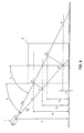
- reading height corresponding to the minimum distance is the difference between the height of the reader and the projection of the minimum reading distance on the wall 5, that in Fig. 4 corresponds to k ⁇ ( ⁇ ) or k2 ( ⁇ ).
- reading height corresponding to the maximum distance is the difference between the height of the reader and the projection of the maximum reading distance on the wall 5, that in Fig. 4 corresponds to k1 ( ⁇ ) or k ⁇ ( ⁇ ).
- the negative value (-18) derives from the fact that the origin of the ordinates coincides with the upper end of the segmentthat represents the minimum height K1. In the particular case illustrated in Fig. 4 the origin of the ordinates thus coincides with the point D.
- Table 3 traditional reader reader of the invention Minimum reading distance (mm) 400 400 Maximum reading distance (mm) 700 700 Initial depth of field (mm) 300 300 Minimum height of label (mm) 0 0 Maximum height of label (mm) 360 360 Height of reader (mm) 574 495 Angles of the light beam 35° 45° 65° Reading height corresponding to the maximum reading distance (mm) 0 0 199 Reading heightcorresponding to the minimum reading distance (mm) 246 212 326 Maximum depth of field (mm) 246 326 Height of label (mm) 17 17 Apparent height of label (mm) 11.9 17.00 36.46 Speed of article (m/sec) 2 2 2 Apparent speed (m/sec) 2.86 2.00 0.93 Number of scans/sec 800 560 240 Number of useful scans on code 4.76 4.76 4.37 Time of dwell on code (ms) 5.95 8.50 18.23
- the apparent speed is represented by the speed of the article/tangent of the angle of the beam.
- the apparent height of the label is represented by the height of the label x the tangent of the angle of the beam.
- the beam having two inclinations provides a number of useful scans on the code equal to 4.76 for the 45° angle and 4.37 for the 65° angle
- the beam having a single inclination of 35° provides a number of useful scans on the code equal to 4.76.
- using a rotor 13 with mirrors having seven mirrors to generate the beam ⁇ and three mirrors for the beam ⁇ provides 560 scans/sec for the beam ⁇ and 240 scans/sec for the beam ⁇ , respectively, for a total of 800 scans/sec.
Landscapes
- Physics & Mathematics (AREA)
- Engineering & Computer Science (AREA)
- Electromagnetism (AREA)
- Artificial Intelligence (AREA)
- Toxicology (AREA)
- General Health & Medical Sciences (AREA)
- Health & Medical Sciences (AREA)
- Computer Vision & Pattern Recognition (AREA)
- General Physics & Mathematics (AREA)
- Theoretical Computer Science (AREA)
- Mechanical Optical Scanning Systems (AREA)
- Cash Registers Or Receiving Machines (AREA)
- Discharge Of Articles From Conveyors (AREA)
- Warehouses Or Storage Devices (AREA)
Claims (28)
- Scanner-Lesegerät (1) für einen optischen Code (7), der sich auf einer Seite eines Artikels (2) befindet, der sich auf das Lesegerät (1) zu bewegt, wobei das Lesegerät (1) eine Erzeugungseinrichtung (10, 13) umfaßt, die in der Lage ist, wenigstens einen Abtastlichtstrahl (8) zu bilden, der in einer Ebene liegt, die gegenüber der besagten Seite um einen vorbestimmten Winkel (ϕ) geneigt ist, und in der Lage ist, den optischen Code (7) in einem vorbestimmten Bereich von Abständen entlang der Richtung der Vorwärtsbewegung des Artikels (2) zu lesen, wobei- der optische Code sich auf einer Vorderseite (5) des Artikels (2) befindet und eine zufällige Position auf der Vorderseite (5) einnimmt, und- die Erzeugungseinrichtung (10, 13) wenigstens einen ersten und einen zweiten Abtastlichtstrahl (8α, 8β) bilden, die in Ebenen liegen, die gegenüber der Vorderseite (5) um einen ersten und einen zweiten vorbestimmten Winkel (α, β) in einer solchen Weise geneigt sind, daß in Verbindung mit der Bewegung des Artikels (2) der erste Abtastlichtstrahl (8α) einen ersten Bereich der Vorderseite mittels einer ersten Mehrzahl von Abtastlinien (81) untersucht und der zweite Abtastlichtstrahl (8β) einen zweiten Bereich der Vorderseite mittels einer zweiten Mehrzahl von Abtastlinien (82) untersucht, so daß der erste Abtastlichtstrahl (8α) in der Lage ist, den optischen Code (7) in einem ersten vorbestimmten Bereich von Abständen entlang der Richtung der Vorwärtsbewegung des Artikels (2) zu lesen und der zweite Abtastlichtstrahl (8β) in der Lage ist, den optischen Code (7) in einem zweiten vorbestimmten Bereich von Abständen entlang der Richtung der Vorwärtsbewegung des Artikels (2) zu lesen, wobei der Gesamtbereich der Abstände, innerhalb dessen der erste und der zweite Abtastlichtstrahl (8α, 8β) in der Lage sind, den optischen Code zu lesen, größer ist, als der vorbestimmte Bereich von Abständen, der durch nur einen Abtastlichtstrahl erreicht werden kann.
- Lesegerät nach Anspruch 1, dadurch gekennzeichnet, daß jeder der Neigungswinkel (α, β) im Bereich von 10° bis 80° liegt.
- Lesegerät nach Anspruch 2, dadurch gekennzeichnet, daß jeder der Neigungswinkel (α, β) im Bereich von 30° bis 70° liegt.
- Lesegerät nach Anspruch 3, dadurch gekennzeichnet, daß jeder der Neigungswinkel (α, β) im Bereich von 40° bis 60° liegt.
- Lesegerät nach Anspruch 1, dadurch gekennzeichnet, daß dem ersten Neigungswinkel (α) eine obere Abtastlinie (81) entspricht und dem zweiten Neigungswinkel (β) eine untere Abtastlinie (82) entspricht, wobei der erste Winkel (α) größer ist als der zweite Winkel (β).
- Lesevorrichtung gemäß Anspruch 5, dadurch gekennzeichnet, daß der erste Neigungswinkel (α) im Bereich von 50° bis 70° liegt und der zweite Neigungswinkel (β) im Bereich von 30° bis 50° liegt.
- Lesegerät nach Anspruch 6, dadurch gekennzeichnet, daß der erste Neigungswinkel (α) 60° beträgt und der zweite Neigungswinkel (β) 40° beträgt.
- Lesegerät nach Anspruch 1, dadurch gekennzeichnet, daß die Erzeugungseinrichtung (10, 13) wenigstens einen dritten Abtastlichtstrahl bildet, der gegenüber der Vorderseite (5) um einen dritten vorbestimmten Winkel geneigt ist, wobei der dritte Abtastlichtstrahl einen dritten Bereich der Vorderseite (5) mittels einer dritten Mehrzahl von Abtastlinien untersucht, wobei der dritte vorbestimmte Winkel einen Wert zwischen dem ersten und dem zweiten Winkel besitzt.
- Lesegerät nach Anspruch 1, dadurch gekennzeichnet, daß die Erzeugungseinrichtung (10, 13) wenigstens einen dritten und einen vierten Abtastlichtstrahl bildet, die um einen dritten und einen vierten vorbestimmten Winkel gegenüber der Vorderseite (5) geneigt sind, wobei der dritte und der vierte Abtastlichtstrahl einen dritten und einen vierten Bereich der Vorderseite (5) mittels einer dritten und einer vierten Mehrzahl von Abtastlinien untersuchen, wobei der dritte und vierte vorbestimmte Winkel Werte zwischen dem ersten und den zweiten Winkel besitzen.
- Lesegerät nach Anspruch 1, dadurch gekennzeichnet, daß die Erzeugungseinrichtungen (10, 13) den ersten Strahl (8α), der die erste Mehrzahl von Abtastlinien (81) erzeugt, mit einer ersten vorbestimmten Anzahl von Abtastungen pro Zeiteinheit (vα), und den zweiten Strahl (8β), der die zweite Mehrzahl von Abtastlinien (82) erzeugt, mit einer zweiten vorbestimmten Anzahl von Abtastungen pro Zeiteinheit (vβ) bildet, wobei die Summe der ersten und zweiten Anzahl von Abtastungen pro Zeiteinheit (vα, vβ) gleich dem Gesamtwert von Abtastungen pro Zeiteinheit ist, die von der Erzeugungseinrichtung (10, 13) abgegeben werden.
- Lesegerät nach Anspruch 1 und 8, dadurch gekennzeichnet, daß die Erzeugungseinrichtung (10, 13) den ersten Strahl, der die erste Mehrzahl von Abtastlinien erzeugt, mit einer ersten Anzahl von Abtastungen pro Zeiteinheit, den zweiten Strahl, der eine zweite Mehrzahl von Abtastlinien erzeugt, mit einer zweiten vorbestimmten Anzahl von Abtastungen pro Zeiteinheit, und den dritten Strahl, der die dritte Mehrzahl von Abtastlinien erzeugt, mit einer dritten vorbestimmten Anzahl von Abtastungen pro Zeiteinheit bildet, wobei die Summe der ersten, zweiten und dritten Anzahl von Abtastungen pro Zeiteinheit gleich dem Gesamtwert von Abtastungen pro Zeiteinheit ist, die von den Erzeugungseinrichtungen (10, 13) abgegeben werden.
- Lesegerät nach Anspruch 1 und 9, dadurch gekennzeichnet, daß die Erzeugungseinrichtung (10, 13) den ersten Strahl, der die erste Mehrzahl von Abtastlinien erzeugt, mit einer ersten vorbestimmten Anzahl von Abtastungen pro Zeiteinheit, den zweiten Strahl, der die zweite Mehrzahl von Abtastlinien erzeugt, mit einer zweiten vorbestimmten Anzahl von Abtastungen pro Zeiteinheit, den dritten Strahl, der die dritte Mehrzahl von Abtastlinien erzeugt, mit einer dritten vorbestimmten Anzahl von Abtastungen pro Zeiteinheit, und den vierten Strahl, der die vierte Mehrzahl von Abtastlinien erzeugt, mit einer vierten vorbestimmten Anzahl von Abtastungen pro Zeiteinheit bildet, wobei die Summe der ersten, zweiten, dritten und vierten Anzahl von Abtastungen pro Zeiteinheit gleich dem Gesamtwert von Abtastungen pro Zeiteinheit ist, die von den Erzeugungseinrichtungen (10, 13) abgegeben werden.
- Lesegerät nach Anspruch 10, dadurch gekennzeichnet, daß die erste und zweite Anzahl von Abtastungen pro Zeiteinheit (vα, vβ) so gewählt sind, daß die Anzahl verwendbarer Abtastungen (nα, nβ) auf dem optischen Code (7) für jede der Mehrzahlen von Abtastlinien (81, 82) im wesentlichen konstant ist.
- Lesegerät nach Anspruch 11, dadurch gekennzeichnet, daß die erste, zweite und dritte Anzahl von Abtastungen pro Zeiteinheit so gewählt sind, daß die Anzahl verwendbarer Abtastungen auf dem optischen Code (7) für jede der Mehrzahlen von Abtastlinien im wesentlichen konstant ist.
- Lesegerät nach Anspruch 12, dadurch gekennzeichnet, daß die erste, zweite, dritte und vierte Anzahl von Abtastungen pro Zeiteinheit so gewählt sind, daß die Anzahl verwendbarer Abtastungen auf dem optischen Code (7) für jede der Mehrzahlen von Abtastlinien im wesentlichen konstant ist.
- Lesegerät nach Anspruch 10, 11 und 12, dadurch gekennzeichnet, daß das Verhältnis zwischen der Anzahl von Abtastungen pro Zeiteinheit jedes Lichtstrahls (vα, vβ) umgekehrt proportional zu dem Tangens des Winkels des gleichen Strahls (tg α, tg β) gegenüber der Vorderseite (5) ist.
- Lesegerät nach Anspruch 13, dadurch gekennzeichnet, daß das Verhältnis zwischen der ersten und der zweiten Anzahl von Abtastungen pro Zeiteinheit (vα, vβ) gleich 7/3 ist.
- Lesegerät nach Anspruch 1, bei dem die Erzeugungseinrichtungen wenigstens eine Quelle (10) eines Lichtstrahls (8) und eine Ablenkeinrichtung für den Lichtstrahl (8) umfassen, die optisch der Lichtquelle (10) zugeordnet ist, dadurch gekennzeichnet, daß die Ablenkeinrichtung einen oszillierenden Spiegel umfaßt, dessen Neigung sich periodisch ändert.
- Lesegerät nach Anspruch 1, bei dem die Erzeugungseinrichtung wenigstens eine Laserquelle (10) eines Lichtstrahls (8) umfassen, dadurch gekennzeichnet, daß die Laserquelle (10) so betrieben wird, daß sie ruckartig zwischen zwei oder mehreren Positionen oszilliert.
- Lesegerät nach Anspruch 1, bei dem die Erzeugungseinrichtung (10, 13) wenigstens eine Quelle (10) eines Lichtstrahls (8) und eine Ablenkeinrichtung (13) für den Lichtstrahl (8) umfassen, die optisch der Quelle zugeordnet ist, dadurch gekennzeichnet, daß die Ablenkeinrichtung (13) einen polygonalen Rotor umfaßt, der sich mit einer vorbestimmten Geschwindigkeit dreht und an dessen Flächen (131, 132) Spiegel vorhanden sind.
- Lesegerät nach Anspruch 1 und 20, dadurch gekennzeichnet, daß der polygonale Rotor (13) eine erste vorbestimmte Anzahl von Spiegeln (131), die um einen vorbestimmten Winkel δ1 gegenüber der Drehachse (14) des Rotors (13) geneigt sind, und eine zweite vorbestimmte Anzahl von Spiegeln (132), die um einen zweiten vorbestimmten Winkel δ2 gegenüber der Drehachse (14) des Rotors (13) geneigt sind, umfaßt, wobei die erste vorbestimmte Anzahl von Spiegeln (131) den ersten Lichtstrahl (8α) bildet und die zweite vorbestimmte Anzahl von Spiegeln (132) den zweiten Lichtstrahl (8β) bildet.
- Lesegerät nach Anspruch 8 und 20, dadurch gekennzeichnet, daß der polygonale Rotor eine erste vorbestimmte Anzahl von Spiegeln, die um einen ersten vorbestimmten Winkel gegenüber der Drehachse des Rotors geneigt sind, eine zweite vorbestimmte Anzahl von Spiegeln, die um einen zweiten vorbestimmten Winkel gegenüber der Drehachse des Rotors geneigt sind, und eine dritte vorbestimmte Anzahl von Spiegeln, die um einen dritten vorbestimmten Winkel gegenüber der Drehachse des Rotors geneigt sind, umfaßt, wobei die erste vorbestimmte Anzahl von Spiegeln den ersten Lichtstrahl bildet, die zweite vorbestimmte Anzahl von Spiegeln den zweiten Lichtstrahl bildet und die dritte vorbestimmte Anzahl von Spiegeln den dritten Lichtstrahl bildet.
- Lesegerät nach Anspruch 9 und 20, dadurch gekennzeichnet, daß der polygonale Rotor eine erste vorbestimmte Anzahl von Spiegeln, die um einen ersten vorbestimmten Winkel gegenüber der Drehachse des Rotors geneigt sind, eine zweite vorbestimmte Anzahl von Spiegeln, die um einen zweiten vorbestimmten Winkel gegenüber der Drehachse des Rotors geneigt sind, eine dritte vorbestimmte Anzahl von Spiegeln, die um einen dritten vorbestimmten Winkel gegenüber der Drehachse des Rotors geneigt sind, und eine vierte vorbestimmte Anzahl von Spiegeln, die um einen vierten vorbestimmten Winkel gegenüber der Drehachse des Rotors geneigt sind, umfaßt, wobei die erste vorbestimmte Anzahl von Spiegeln den ersten Lichtstrahl bildet, die zweite vorbestimmte Anzahl von Spiegeln den zweiten Lichtstrahl bildet, die dritte vorbestimmte Anzahl von Spiegeln den dritten Lichtstrahl bildet und die vierte vorbestimmte Anzahl von Spiegeln den vierten Lichtstrahl bildet.
- Lesegerät nach Anspruch 21, dadurch gekennzeichnet, daß der Winkel δ1, δ2 der Spiegel (131, 132) des Rotors (13) supplementär sind.
- Lesegerät nach Anspruch 24, dadurch gekennzeichnet, daß der Winkel δ1 im Bereich von +5° bis +15° liegt.
- Lesegerät nach Anspruch 25, dadurch gekennzeichnet, daß der Winkel δ1 im Bereich von +7° bis +9° liegt.
- Lesegerät nach Anspruch 21, dadurch gekennzeichnet, daß der polygonale Rotor (13) zehn Flächen und eine Abfolge der Spiegel von 3-1-2-1-2-1 besitzt.
- Verfahren zum Abtasten eines optischen Codes (7), der sich auf einer Vorderseite (5) eines Artikels (10) befindet, der sich auf ein Scanner-Lesegerät (1) zu bewegt und eine zufällige Position auf der Vorderseite (5) einnimmt, welches folgendes umfaßt:- Bilden wenigstens eines ersten und eines zweiten Abtastlichtstrahls (8α, 8β), die in Ebenen liegen, welche um einen ersten und einen zweiten vorbestimmten Winkel (α, β) gegenüber der Vorderseite geneigt sind, und in der Lage sind, den optischen Code (7) in einem entsprechenden vorbestimmten Bereich von Abständen entlang der Richtung der Vorwärtsbewegung des Artikels (2) zu lesen,- Verursachen, daß der erste Abtastlichtstrahl (8α) in Verbindung mit der Bewegung des Artikels (2) einen ersten Bereich der Vorderseite (5) mittels einer ersten Mehrzahl von Abtastlinien (81) untersucht, und- Verursachen, daß der zweite Abtastlichtstrahl (8β) in Verbindung mit der Bewegung des Artikels (2) einen zweiten Bereich der Vorderseite (5) mittels einer zweiten Mehrzahl von Abtastlinien (82) untersucht, so daß:wobei der gesamte Bereich von Abständen, innerhalb dessen der erste und zweite Abtastlichtstrahl (8α, 8β) den optischen Code (7) lesen, größer ist als der vorbestimmte Bereich von Abständen, der von nur einem Abtastlichtstrahl erreicht werden kann.- der erste Abtastlichtstrahl (8α) den optischen Code (7) in einem ersten vorbestimmten Bereich von Abständen entlang der Richtung der Vorwärtsbewegung des Artikels (2) liest und- der zweite Abtastlichtstrahl (8β) den optischen Code (7) in einem zweiten vorbestimmten Bereich von Abständen entlang der Richtung der Vorwärtsbewegung des Artikels (2) liest,
Applications Claiming Priority (2)
| Application Number | Priority Date | Filing Date | Title |
|---|---|---|---|
| IT96MI002595A IT1289438B1 (it) | 1996-12-11 | 1996-12-11 | Lettore a scansione di un codice ottico posto su un articolo in movimento e metodo di scansione di detto codice ottico mediante detto |
| ITMI962595 | 1996-12-11 |
Publications (4)
| Publication Number | Publication Date |
|---|---|
| EP0848344A2 EP0848344A2 (de) | 1998-06-17 |
| EP0848344A3 EP0848344A3 (de) | 1998-09-02 |
| EP0848344B1 EP0848344B1 (de) | 2002-10-16 |
| EP0848344B2 true EP0848344B2 (de) | 2006-07-12 |
Family
ID=11375377
Family Applications (1)
| Application Number | Title | Priority Date | Filing Date |
|---|---|---|---|
| EP97203806A Expired - Lifetime EP0848344B2 (de) | 1996-12-11 | 1997-12-04 | Vorrichtung zum Abtasten eines sich auf einem bewegenden Artikel befindlichen optischen Kodes und Verfahren zum Abtasten eines solchen optischen Kodes mittels dieser Abtastvorrichtung |
Country Status (6)
| Country | Link |
|---|---|
| US (1) | US6135352A (de) |
| EP (1) | EP0848344B2 (de) |
| JP (1) | JP4079203B2 (de) |
| AT (1) | ATE226338T1 (de) |
| DE (1) | DE69716393T3 (de) |
| IT (1) | IT1289438B1 (de) |
Families Citing this family (12)
| Publication number | Priority date | Publication date | Assignee | Title |
|---|---|---|---|---|
| DE19840455A1 (de) * | 1998-09-04 | 2000-03-09 | Sick Ag | Verfahren zum Betreiben eines Strichcodelesers |
| US6808115B2 (en) * | 1998-09-11 | 2004-10-26 | Accu-Sort Systems, Inc. | Quasi-coaxial optical bar code reader |
| US6502750B1 (en) * | 1999-11-24 | 2003-01-07 | Microscan Systems, Inc. | Scanning beam system and method for reading information symbols |
| US6739513B1 (en) * | 2000-09-05 | 2004-05-25 | Rjs Systems International | Box detector in barcode environment |
| US6749110B2 (en) * | 2001-07-03 | 2004-06-15 | Accu-Sort Systems, Inc. | Synchronously sweeping line scan imager |
| GB2461270A (en) * | 2008-06-24 | 2009-12-30 | Neopost Technologies | Optical code reader |
| US9892298B2 (en) | 2012-02-06 | 2018-02-13 | Cognex Corporation | System and method for expansion of field of view in a vision system |
| US8646690B2 (en) | 2012-02-06 | 2014-02-11 | Cognex Corporation | System and method for expansion of field of view in a vision system |
| US11966810B2 (en) | 2012-02-06 | 2024-04-23 | Cognex Corporation | System and method for expansion of field of view in a vision system |
| US9027838B2 (en) | 2012-02-06 | 2015-05-12 | Cognex Corporation | System and method for expansion of field of view in a vision system |
| DE102017127420A1 (de) * | 2017-11-21 | 2019-05-23 | Sick Ag | Polygonscanner und Verfahren zum Erfassen von Objekten in einem Überwachungsbereich |
| KR102284337B1 (ko) * | 2019-08-28 | 2021-08-02 | (주)카네비컴 | 라이다 장치 및 이의 동작 방법 |
Citations (2)
| Publication number | Priority date | Publication date | Assignee | Title |
|---|---|---|---|---|
| DE3728211A1 (de) † | 1987-08-24 | 1989-03-16 | Sick Optik Elektronik Erwin | Scanner zur erfassung von strichcodes auf gegenstaenden |
| EP0650134A2 (de) † | 1993-10-22 | 1995-04-26 | Erwin Sick GmbH Optik-Elektronik | Barcodeleser und Verfahren zu seinem Betrieb |
Family Cites Families (19)
| Publication number | Priority date | Publication date | Assignee | Title |
|---|---|---|---|---|
| US3728677A (en) * | 1971-05-10 | 1973-04-17 | Stanford Research Inst | Rotation-independent reading of rectangular insignia |
| US3701098A (en) * | 1971-06-15 | 1972-10-24 | Scanner | Device for machine reading of information without manipulation of the information carrier |
| US3899687A (en) * | 1972-07-10 | 1975-08-12 | Identicon Corp | Optical label scanning |
| JPS5592972A (en) * | 1979-01-08 | 1980-07-14 | Nec Corp | Bar code read method |
| US4753498A (en) * | 1985-03-22 | 1988-06-28 | Tokyo Kogaku Kikai Kabushiki Kaisha | Optical reader |
| US4843222A (en) * | 1986-05-29 | 1989-06-27 | Eastman Kodak Company | Bar code reader for reading bar code symbols at different distances |
| US4939355A (en) * | 1988-01-22 | 1990-07-03 | Spectra-Physics, Inc. | Automatic package label scanner |
| US5254844A (en) * | 1988-05-11 | 1993-10-19 | Symbol Technologies, Inc. | Mirrorless scanners with movable laser, optical and sensor components |
| US5144120A (en) * | 1988-05-11 | 1992-09-01 | Symbol Technologies, Inc. | Mirrorless scanners with movable laser, optical and sensor components |
| US5569901A (en) * | 1988-10-21 | 1996-10-29 | Symbol Technologies, Inc. | Symbol scanning system and method having adaptive pattern generation |
| JP2771593B2 (ja) * | 1989-04-20 | 1998-07-02 | 富士通株式会社 | 光走査装置 |
| US5175421A (en) * | 1989-05-01 | 1992-12-29 | International Business Machines Corporation | Dual depth of field deflector for bar code scanners |
| DE3942932A1 (de) * | 1989-12-23 | 1991-06-27 | Licentia Gmbh | Verfahren zum verteilen von paketen o. ae. |
| US5206491A (en) * | 1990-03-02 | 1993-04-27 | Fujitsu Limited | Plural beam, plural window multi-direction bar code reading device |
| US5200597A (en) * | 1991-02-07 | 1993-04-06 | Psc, Inc. | Digitally controlled system for scanning and reading bar codes |
| US5392150A (en) * | 1991-05-15 | 1995-02-21 | Nippondenso Co., Ltd. | Optical information reading device |
| JP2789282B2 (ja) * | 1992-07-10 | 1998-08-20 | 富士通株式会社 | 光学式マーク読取装置 |
| IT1264733B1 (it) * | 1993-11-04 | 1996-10-04 | Datalogic Spa | Dispositivo di lettura o scanner a laser per la lettura di caratteri aventi un diverso grado di riflettenza, in particolare di codici a |
| JP3213670B2 (ja) * | 1994-05-30 | 2001-10-02 | 東芝テック株式会社 | チェックアウト装置 |
-
1996
- 1996-12-11 IT IT96MI002595A patent/IT1289438B1/it active IP Right Grant
-
1997
- 1997-12-04 AT AT97203806T patent/ATE226338T1/de not_active IP Right Cessation
- 1997-12-04 DE DE69716393T patent/DE69716393T3/de not_active Expired - Lifetime
- 1997-12-04 EP EP97203806A patent/EP0848344B2/de not_active Expired - Lifetime
- 1997-12-10 US US08/988,426 patent/US6135352A/en not_active Expired - Fee Related
- 1997-12-10 JP JP34021397A patent/JP4079203B2/ja not_active Expired - Fee Related
Patent Citations (2)
| Publication number | Priority date | Publication date | Assignee | Title |
|---|---|---|---|---|
| DE3728211A1 (de) † | 1987-08-24 | 1989-03-16 | Sick Optik Elektronik Erwin | Scanner zur erfassung von strichcodes auf gegenstaenden |
| EP0650134A2 (de) † | 1993-10-22 | 1995-04-26 | Erwin Sick GmbH Optik-Elektronik | Barcodeleser und Verfahren zu seinem Betrieb |
Also Published As
| Publication number | Publication date |
|---|---|
| DE69716393T2 (de) | 2003-06-12 |
| DE69716393T3 (de) | 2007-02-01 |
| EP0848344B1 (de) | 2002-10-16 |
| IT1289438B1 (it) | 1998-10-15 |
| ITMI962595A0 (it) | 1996-12-11 |
| JP4079203B2 (ja) | 2008-04-23 |
| ATE226338T1 (de) | 2002-11-15 |
| JPH10177617A (ja) | 1998-06-30 |
| EP0848344A2 (de) | 1998-06-17 |
| EP0848344A3 (de) | 1998-09-02 |
| ITMI962595A1 (it) | 1998-06-11 |
| US6135352A (en) | 2000-10-24 |
| DE69716393D1 (de) | 2002-11-21 |
Similar Documents
| Publication | Publication Date | Title |
|---|---|---|
| EP0494647B1 (de) | Laserstrahlabtaster | |
| US3902048A (en) | Omnidirectional optomechanical scanning apparatus | |
| EP0848344B2 (de) | Vorrichtung zum Abtasten eines sich auf einem bewegenden Artikel befindlichen optischen Kodes und Verfahren zum Abtasten eines solchen optischen Kodes mittels dieser Abtastvorrichtung | |
| US5393967A (en) | Method and apparatus for non-contact reading of a relief pattern | |
| US5648649A (en) | Flying spot optical scanner with a high speed dithering motion | |
| JPH0628508A (ja) | 光学読取方法および光学読取装置 | |
| EP0691622A1 (de) | Strahlformung für optische Scanner | |
| ATE173844T1 (de) | Strichkodeleser | |
| EP0905641A1 (de) | Optische Abtastvorrichtung | |
| US5179271A (en) | Compact optical scan pattern generator for bar code reading systems | |
| ATE201107T1 (de) | Optischer codeabtaster mit sich entlang zwei unterschiedlichen optischen wegen bewegenden laserstrahlen | |
| EP0159024A2 (de) | Optischer Abtastapparat | |
| US5979761A (en) | Bar code laser scanner having a plurality of adjustable mirrors | |
| EP0874328A3 (de) | Strichkode-Abtastanordnung | |
| US4806753A (en) | Light scanning device with a short-path synchronizing grid | |
| EP0572685A1 (de) | Vorrichtung zum Lesen von Symbolen mit Fokusveränderung eines Laserabtaststrahles durch optische Weglängeveränderung | |
| EP0435100B1 (de) | Symbolabtaster | |
| EP0458334B1 (de) | Lesegerät für Balkenkodierungen | |
| JPH05205088A (ja) | 光学スキャナの焦点変更装置および方法 | |
| JPH11231239A (ja) | 光学走査装置 | |
| US6820811B1 (en) | Dual focal length bar code scanner | |
| EP0533383A2 (de) | Optische Abtastvorrichtung | |
| JPH01321582A (ja) | バーコード読取装置 | |
| KR930005753Y1 (ko) | 바코드 레이저 스캐너의 레이저 주사장치 | |
| JP2729729B2 (ja) | ラスタースキャン方式バーコードリーダ |
Legal Events
| Date | Code | Title | Description |
|---|---|---|---|
| PUAI | Public reference made under article 153(3) epc to a published international application that has entered the european phase |
Free format text: ORIGINAL CODE: 0009012 |
|
| AK | Designated contracting states |
Kind code of ref document: A2 Designated state(s): AT BE CH DE DK ES FR GB GR IT LI NL PT SE |
|
| AX | Request for extension of the european patent |
Free format text: AL;LT;LV;MK;RO;SI |
|
| PUAL | Search report despatched |
Free format text: ORIGINAL CODE: 0009013 |
|
| AK | Designated contracting states |
Kind code of ref document: A3 Designated state(s): AT BE CH DE DK ES FI FR GB GR IE IT LI LU MC NL PT SE |
|
| AX | Request for extension of the european patent |
Free format text: AL;LT;LV;MK;RO;SI |
|
| 17P | Request for examination filed |
Effective date: 19990218 |
|
| AKX | Designation fees paid |
Free format text: AT BE CH DE DK ES FR GB GR IT LI NL PT |
|
| RBV | Designated contracting states (corrected) |
Designated state(s): AT BE CH DE DK ES FR GB GR IT LI NL PT |
|
| RBV | Designated contracting states (corrected) |
Designated state(s): AT BE CH DE DK ES FR GB GR IT LI NL PT SE |
|
| RAP1 | Party data changed (applicant data changed or rights of an application transferred) |
Owner name: DATALOGIC S.P.A. |
|
| 17Q | First examination report despatched |
Effective date: 20010508 |
|
| GRAG | Despatch of communication of intention to grant |
Free format text: ORIGINAL CODE: EPIDOS AGRA |
|
| GRAG | Despatch of communication of intention to grant |
Free format text: ORIGINAL CODE: EPIDOS AGRA |
|
| GRAG | Despatch of communication of intention to grant |
Free format text: ORIGINAL CODE: EPIDOS AGRA |
|
| GRAH | Despatch of communication of intention to grant a patent |
Free format text: ORIGINAL CODE: EPIDOS IGRA |
|
| GRAH | Despatch of communication of intention to grant a patent |
Free format text: ORIGINAL CODE: EPIDOS IGRA |
|
| GRAA | (expected) grant |
Free format text: ORIGINAL CODE: 0009210 |
|
| AK | Designated contracting states |
Kind code of ref document: B1 Designated state(s): AT BE CH DE DK ES FR GB GR IT LI NL PT SE |
|
| PG25 | Lapsed in a contracting state [announced via postgrant information from national office to epo] |
Ref country code: NL Free format text: LAPSE BECAUSE OF FAILURE TO SUBMIT A TRANSLATION OF THE DESCRIPTION OR TO PAY THE FEE WITHIN THE PRESCRIBED TIME-LIMIT Effective date: 20021016 Ref country code: LI Free format text: LAPSE BECAUSE OF FAILURE TO SUBMIT A TRANSLATION OF THE DESCRIPTION OR TO PAY THE FEE WITHIN THE PRESCRIBED TIME-LIMIT Effective date: 20021016 Ref country code: GR Free format text: LAPSE BECAUSE OF FAILURE TO SUBMIT A TRANSLATION OF THE DESCRIPTION OR TO PAY THE FEE WITHIN THE PRESCRIBED TIME-LIMIT Effective date: 20021016 Ref country code: CH Free format text: LAPSE BECAUSE OF FAILURE TO SUBMIT A TRANSLATION OF THE DESCRIPTION OR TO PAY THE FEE WITHIN THE PRESCRIBED TIME-LIMIT Effective date: 20021016 Ref country code: BE Free format text: LAPSE BECAUSE OF FAILURE TO SUBMIT A TRANSLATION OF THE DESCRIPTION OR TO PAY THE FEE WITHIN THE PRESCRIBED TIME-LIMIT Effective date: 20021016 Ref country code: AT Free format text: LAPSE BECAUSE OF FAILURE TO SUBMIT A TRANSLATION OF THE DESCRIPTION OR TO PAY THE FEE WITHIN THE PRESCRIBED TIME-LIMIT Effective date: 20021016 |
|
| REF | Corresponds to: |
Ref document number: 226338 Country of ref document: AT Date of ref document: 20021115 Kind code of ref document: T |
|
| REG | Reference to a national code |
Ref country code: GB Ref legal event code: FG4D |
|
| REG | Reference to a national code |
Ref country code: CH Ref legal event code: EP |
|
| REF | Corresponds to: |
Ref document number: 69716393 Country of ref document: DE Date of ref document: 20021121 |
|
| PG25 | Lapsed in a contracting state [announced via postgrant information from national office to epo] |
Ref country code: SE Free format text: LAPSE BECAUSE OF FAILURE TO SUBMIT A TRANSLATION OF THE DESCRIPTION OR TO PAY THE FEE WITHIN THE PRESCRIBED TIME-LIMIT Effective date: 20030116 Ref country code: PT Free format text: LAPSE BECAUSE OF FAILURE TO SUBMIT A TRANSLATION OF THE DESCRIPTION OR TO PAY THE FEE WITHIN THE PRESCRIBED TIME-LIMIT Effective date: 20030116 Ref country code: DK Free format text: LAPSE BECAUSE OF FAILURE TO SUBMIT A TRANSLATION OF THE DESCRIPTION OR TO PAY THE FEE WITHIN THE PRESCRIBED TIME-LIMIT Effective date: 20030116 |
|
| NLV1 | Nl: lapsed or annulled due to failure to fulfill the requirements of art. 29p and 29m of the patents act | ||
| PG25 | Lapsed in a contracting state [announced via postgrant information from national office to epo] |
Ref country code: ES Free format text: LAPSE BECAUSE OF FAILURE TO SUBMIT A TRANSLATION OF THE DESCRIPTION OR TO PAY THE FEE WITHIN THE PRESCRIBED TIME-LIMIT Effective date: 20030429 |
|
| REG | Reference to a national code |
Ref country code: CH Ref legal event code: PL |
|
| ET | Fr: translation filed | ||
| PLBQ | Unpublished change to opponent data |
Free format text: ORIGINAL CODE: EPIDOS OPPO |
|
| PLBI | Opposition filed |
Free format text: ORIGINAL CODE: 0009260 |
|
| PLAX | Notice of opposition and request to file observation + time limit sent |
Free format text: ORIGINAL CODE: EPIDOSNOBS2 |
|
| 26 | Opposition filed |
Opponent name: SICK AG Effective date: 20030709 |
|
| PLAX | Notice of opposition and request to file observation + time limit sent |
Free format text: ORIGINAL CODE: EPIDOSNOBS2 |
|
| PLAX | Notice of opposition and request to file observation + time limit sent |
Free format text: ORIGINAL CODE: EPIDOSNOBS2 |
|
| PLBB | Reply of patent proprietor to notice(s) of opposition received |
Free format text: ORIGINAL CODE: EPIDOSNOBS3 |
|
| PUAH | Patent maintained in amended form |
Free format text: ORIGINAL CODE: 0009272 |
|
| STAA | Information on the status of an ep patent application or granted ep patent |
Free format text: STATUS: PATENT MAINTAINED AS AMENDED |
|
| 27A | Patent maintained in amended form |
Effective date: 20060712 |
|
| AK | Designated contracting states |
Kind code of ref document: B2 Designated state(s): AT BE CH DE DK ES FR GB GR IT LI NL PT SE |
|
| REG | Reference to a national code |
Ref country code: ES Ref legal event code: FD2A Effective date: 20021205 |
|
| ET3 | Fr: translation filed ** decision concerning opposition | ||
| PGFP | Annual fee paid to national office [announced via postgrant information from national office to epo] |
Ref country code: GB Payment date: 20091125 Year of fee payment: 13 |
|
| PGFP | Annual fee paid to national office [announced via postgrant information from national office to epo] |
Ref country code: FR Payment date: 20100115 Year of fee payment: 13 |
|
| PGFP | Annual fee paid to national office [announced via postgrant information from national office to epo] |
Ref country code: IT Payment date: 20101127 Year of fee payment: 14 |
|
| PGFP | Annual fee paid to national office [announced via postgrant information from national office to epo] |
Ref country code: DE Payment date: 20101208 Year of fee payment: 14 |
|
| GBPC | Gb: european patent ceased through non-payment of renewal fee |
Effective date: 20101204 |
|
| REG | Reference to a national code |
Ref country code: FR Ref legal event code: ST Effective date: 20110831 |
|
| PG25 | Lapsed in a contracting state [announced via postgrant information from national office to epo] |
Ref country code: FR Free format text: LAPSE BECAUSE OF NON-PAYMENT OF DUE FEES Effective date: 20110103 |
|
| PG25 | Lapsed in a contracting state [announced via postgrant information from national office to epo] |
Ref country code: GB Free format text: LAPSE BECAUSE OF NON-PAYMENT OF DUE FEES Effective date: 20101204 |
|
| REG | Reference to a national code |
Ref country code: DE Ref legal event code: R119 Ref document number: 69716393 Country of ref document: DE Effective date: 20120703 |
|
| PG25 | Lapsed in a contracting state [announced via postgrant information from national office to epo] |
Ref country code: DE Free format text: LAPSE BECAUSE OF NON-PAYMENT OF DUE FEES Effective date: 20120703 |
|
| PG25 | Lapsed in a contracting state [announced via postgrant information from national office to epo] |
Ref country code: IT Free format text: LAPSE BECAUSE OF NON-PAYMENT OF DUE FEES Effective date: 20111204 |