EP0848400A2 - Interrupteur électrique - Google Patents
Interrupteur électrique Download PDFInfo
- Publication number
- EP0848400A2 EP0848400A2 EP97121282A EP97121282A EP0848400A2 EP 0848400 A2 EP0848400 A2 EP 0848400A2 EP 97121282 A EP97121282 A EP 97121282A EP 97121282 A EP97121282 A EP 97121282A EP 0848400 A2 EP0848400 A2 EP 0848400A2
- Authority
- EP
- European Patent Office
- Prior art keywords
- contact
- lever arm
- movement
- bearing
- housing
- Prior art date
- Legal status (The legal status is an assumption and is not a legal conclusion. Google has not performed a legal analysis and makes no representation as to the accuracy of the status listed.)
- Granted
Links
Images

Classifications
-
- H—ELECTRICITY
- H01—ELECTRIC ELEMENTS
- H01H—ELECTRIC SWITCHES; RELAYS; SELECTORS; EMERGENCY PROTECTIVE DEVICES
- H01H5/00—Snap-action arrangements, i.e. in which during a single opening operation or a single closing operation energy is first stored and then released to produce or assist the contact movement
- H01H5/04—Energy stored by deformation of elastic members
- H01H5/045—Energy stored by deformation of elastic members making use of cooperating spring loaded wedging or camming parts between operating member and contact structure
-
- H—ELECTRICITY
- H01—ELECTRIC ELEMENTS
- H01H—ELECTRIC SWITCHES; RELAYS; SELECTORS; EMERGENCY PROTECTIVE DEVICES
- H01H13/00—Switches having rectilinearly-movable operating part or parts adapted for pushing or pulling in one direction only, e.g. push-button switch
- H01H13/02—Details
- H01H13/26—Snap-action arrangements depending upon deformation of elastic members
-
- H—ELECTRICITY
- H01—ELECTRIC ELEMENTS
- H01H—ELECTRIC SWITCHES; RELAYS; SELECTORS; EMERGENCY PROTECTIVE DEVICES
- H01H9/00—Details of switching devices, not covered by groups H01H1/00 - H01H7/00
- H01H9/02—Bases, casings, or covers
- H01H9/06—Casing of switch constituted by a handle serving a purpose other than the actuation of the switch, e.g. by the handle of a vacuum cleaner
-
- H—ELECTRICITY
- H01—ELECTRIC ELEMENTS
- H01H—ELECTRIC SWITCHES; RELAYS; SELECTORS; EMERGENCY PROTECTIVE DEVICES
- H01H1/00—Contacts
- H01H1/12—Contacts characterised by the manner in which co-operating contacts engage
- H01H1/14—Contacts characterised by the manner in which co-operating contacts engage by abutting
- H01H1/18—Contacts characterised by the manner in which co-operating contacts engage by abutting with subsequent sliding
-
- H—ELECTRICITY
- H01—ELECTRIC ELEMENTS
- H01H—ELECTRIC SWITCHES; RELAYS; SELECTORS; EMERGENCY PROTECTIVE DEVICES
- H01H1/00—Contacts
- H01H1/58—Electric connections to or between contacts; Terminals
- H01H1/5833—Electric connections to or between contacts; Terminals comprising an articulating, sliding or rolling contact between movable contact and terminal
-
- H—ELECTRICITY
- H01—ELECTRIC ELEMENTS
- H01H—ELECTRIC SWITCHES; RELAYS; SELECTORS; EMERGENCY PROTECTIVE DEVICES
- H01H15/00—Switches having rectilinearly-movable operating part or parts adapted for actuation in opposite directions, e.g. slide switch
- H01H15/02—Details
- H01H15/06—Movable parts; Contacts mounted thereon
- H01H15/16—Driving mechanisms
- H01H15/18—Driving mechanisms acting with snap action
Definitions
- the invention relates to an electrical switch according to the Preamble of claim 1.
- Such electrical switches are used in particular in Power tools, such as drills, jigsaws, circular saws, Electric planing or the like, used.
- From DE-OS 28 38 934 is an electrical switch for Power tools known, which is arranged in a housing, from a switching contact and a fixed contact existing contact system owns.
- An actuator is movably mounted on the housing Action on the contact system so that the contact system between an unactuated and an actuated position switches.
- the Switch contact arranged pivotably on a bearing is of the type a lever formed with two lever arms, being on the first Lever arm of the switch contact a spring for exercising on the Fixed contact acts force.
- the actuator moves a cam control, which in turn with the second lever arm of the Switch contact interacts to switch the contact system.
- the contact system is roughly the same arranged parallel to the actuation axis in the housing, the Switch contact in the actuated position approximately in Direction of movement of the actuator runs. Because for easy Assembly of the switch in power tools is often required that the connections of the supply lines for the power supply to the Bottom of the switch housing is the Current flow in the housing from the connections to the contact system complex. Is the electrical switch as a multi-pole switch with designed several contact systems, so is a relatively large Housing required to accommodate the contact systems. In slim Handles of power tools is the placement of a such switch often difficult.
- the invention has for its object the power supply for Simplify contact system in the electrical switch.
- the current flow in the electrical switch is according to the invention simplified that the contact system is substantially transverse to Actuating axis of the switch is arranged so that the first Lever arm of the switch contact in the actuated position with his Longitudinal direction deviates from the actuation axis. Further refinements of the invention are the subject of Subclaims.
- the switching contact of the contact system on Bearing is arranged that the first lever arm of the switching contact in the actuated position with its longitudinal direction approximately perpendicular to the direction of movement of the actuator and / or the Cam control is also in the unactuated position of the switching contact with an angle of at least 45 degrees to Direction of movement is directed. This can then expediently Angles between 50 and 70 degrees.
- a plunger can be arranged on the housing in a linearly movable manner Actuator be rigidly coupled so that the actuation axis is formed by the plunger. Next is on the inside of the case located part of the tappet of the cams for the second Interacting cam control arranged lever arm.
- the current flow in the contact system is approximately perpendicular to Direction of movement of the actuator and / or the cam control designed.
- the connecting line between the Fixed contact and the current bearing for the switch contact in approximately perpendicular to the direction of movement.
- the fixed contact can continue attached directly to a connector for an electrical supply line be, the connecting part in particular on the underside of the Housing is located.
- the bearing for the switch contact can with are a further connection part in electrical connection, wherein in particular the further connection part is designed as a plug contact and protrudes from the top of the case. Conveniently is then the further connecting part with the bearing as one piece Stamped part formed. With such a training Power tool switch are thus the power and Motor connections on one long side of the housing.
- the switch contact has a game in Camp.
- the means to exert a force at first Lever arm of the switching contact arranged such that the line of action of Force in the unactuated position of the switch contact from the vertical Direction deviates to the first lever arm, creating an additional Force component exerted on the switch contact in the direction of the bearing becomes.
- the cam on the cam control then essentially acts until the actuated position is reached on the second Lever arm that this additional force component is compensated.
- the end of the second end facing away from the bearing Lever arm angled at an angle to the longitudinal direction of the second Lever arm can be arranged.
- the slope acts with the cam Cam control in the manner of an inclined plane together.
- the actuated position gives the cam the second lever arm largely free, which then makes the cleaning, rubbing Movement of the switching contact on the fixed contact towards the bearing he follows.
- the automatic cleaning of the contact system can help simpler designs of the switch even on a seal on the Point where the plunger leads into the housing can be omitted. If dirt penetrates the interior of the housing at this point, do so this dirt cannot have a detrimental effect on the service life of the contact system.
- two contact systems are in the housing Direction of movement arranged side by side. Then it offers itself further on, the switch contact, the fixed contact and the bearing as well if necessary, with the bearing and the fixed contact in electrical Connected connecting parts are identical for both contact systems train, so that advantageously the number of different parts is reduced.
- the switch has a means to inhibit the movement of the actuator.
- This means is in a certain movement position in active connection with the Actuator can be brought so that in this movement position Pressure point for the actuator can be generated.
- the means of Inhibition can consist of a spigot and one in the movement path of the Pin located passage opening exist, the Passage opening at the narrowest point a smaller width than that has the largest cross section of the pin.
- the pin can be on the part of the plunger located inside the housing, the Pin on the plunger can be molded as an extension of the cam.
- the passage opening is preferably conical by two running guide surfaces with different steep slopes trained on both sides of the narrowest point.
- the guide surfaces can be located on an inner wall of the housing and for example, be molded on the inner wall.
- the inhibitor is designed such that the Active connection when switching from the unactuated position to actuated position of the contact system with greater intensity than in the reverse direction of movement of the actuator becomes.
- the housing for the switch consists of two housing parts, namely from a base and a lid.
- the base In the base are the contact system, the connections and the guide for the actuator with the Tappet added.
- the guide surfaces for the inhibitor the movement of the actuator are on the inside of the lid.
- Around the two housing parts are groove and Spring connections arranged. Because of this after assembly interlocking tongue and groove connections form the Transition gap between the two housing parts of a kind Labyrinth, so that the interior of the housing is largely dust-tight is.
- the switch housing has a small installation volume, even if it is a multi-pole switch. Thereby this switch can be made from slim Power tools are used, so that the overall ergonomics of the power tool is increased. Because the contact system Space-saving is arranged in the housing, it can be enlarged without Space required due to wide contact surfaces on the switch contacts, large ones Contact areas u. The like. Also dimensioned for high switching capacities will.
- the inventive design of the contact system ensures a high contact force in the actuated position. This in turn reduces the contact erosion. Furthermore, a good self-cleaning of the Contact areas can be achieved when switching. Thus the Lifetime of the switch increased.
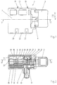
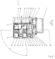
- an electrical switch 1 which as Power switch for use in power tools, such as drills, Jigsaws, circular saws or the like.
- the switch 1 has a housing 2, on which a serving as a manual handle, in the Form of a handle formed actuator 3 linearly movable in a direction of movement according to arrows 19, 19 ' is arranged.
- a plunger 4 is rigid coupled, which extends into the housing interior 5 of the housing 2, such as 3 can be seen.
- the plunger 4 has a receptacle 6 for a compression spring 7 the actuator 3 by the user together with the plunger 4 in Direction of arrow 19 against the restoring force of the compression spring 7, which acts in the direction of arrow 19 ', movable.
- a contact system 8 which consists of a switch contact 9 and a Fixed contact 10 exists.
- the switch contact 9 is pivotable on a bearing 11 arranged and in the manner of a lever with two Lever arms 12, 13 formed.
- first lever arm 12 of the switching contact 9 acts an elastic means to exert a force directed at the fixed contact 10.
- a compression spring trained spring 14 which has one end in a receptacle 15 in Housing inner 5 and at the other end to a shoulder 16 on first lever arm 12 is held.
- the actuator 3 acts on the plunger 4 in certain Movement positions in such a way on the contact system 8 that the Contact system 8 between an unactuated position, which in Fig. 3rd can be seen, and an actuated position, which can be seen in Fig. 4 is, switches.
- the contact surface 38 lies of the switching contact 9 on the fixed contact 10, so that the switch 1 is switched on.
- the unactuated position the Contact surface 38 of the switching contact 9, however, a distance from Fixed contact 10, with which the switch 1 is switched off.
- the actuating member 3 acts to switch the contact system 8 a cam control 17 with the second lever arm 13 of the Switch contact 9 together.
- the cam control 17 has one Cam 18, which on the inside of the housing 5 part of the Ram 4 is arranged.
- the cam 18 acts in the unactuated position, the second lever arm 13 and gives in the actuated position the second lever arm 13 free. So that's right in the present case, the direction of movement of the actuator 3 that of the cam controller 17 match.
- a Locking button 43 which is shown in Fig. 2, it can Actuator 3 in the actuated position of the contact system 8 lock.
- the contact system 8 is transverse to the direction of movement 19, 19 'arranged in the housing 2.
- Switch contact 9 is for this purpose so arranged on the bearing 11 that the first lever arm 12 in the actuated position of the switch contact 9 with its longitudinal direction deviating from the parallel lines 39 running through the bearing 11 Direction of movement 19, 19 'of the actuator 3 and the plunger 4th or the cam controller 17 is directed.
- the parallel 39 is in 3 and 4 are drawn with a broken line.
- the one in Fig. 4 specified angles ⁇ between the first lever arm 12 and the Parallels 39 to the direction of movement 19, 19 'is thus greater than 0 Degree.
- the Angle ⁇ between the first lever arm 12 and the parallel 39 to Direction of movement 19, 19 'of the actuator 3 at least 45 degrees is, so that conversely the angle ⁇ between the first lever arm 12 and the perpendicular 40 to the direction of movement 19, 19 'at most 45 Degrees.
- the angle ⁇ is between 50 and 70 degrees, which in turn can be seen in more detail in FIG. 3.
- the Current flow in the contact system 8 in a special way and in fact approximately perpendicular to the direction of movement 19, 19 'of the actuator 3 or the cam control 17.
- the fixed contact 10 and current-bearing 11 in the housing interior 5 arranged such that the imaginary connecting line between the fixed contact 10 and the bearing 11 for the switch contact 9 approximately perpendicular to the direction of movement 19, 19 'of the actuator 3 is and thus approximately in the direction the vertical 40 runs.
- the fixed contact 10 is for further optimization of the current flow directly on a connecting part 20 for the supply line to Power supply or for the mains lead to switch 1 attached.
- the connecting part 20 can, for example, as a cuboid Part be made of copper, this on one surface Part of the fixed contact 10 attached in the form of a contact rivet is.
- the connecting part 20 is on the underside 22 of the housing 2 located and has a screw connection 24 for fastening the Power supply.
- the bearing 11 for the switch contact 9 is with another Connection part 21 in electrical connection.
- the other connector 21 is designed as a plug contact 25, which on the top 23 of the Housing 2 protrudes.
- the leads are connected to the plug contact 25 connected to the electric motor of the power tool.
- the further connection part 21 with the bearing 11 as an integral stamped part is formed.
- the further connecting part 21 is approximately parallel to the vertical 40 in the housing interior 5 arranged, the bearing 11 being bent on the further connecting part 21 is.
- the power supply lines are on the bottom 22 and the leads for the electric motor on the top 23 of the electrical switch 1 connected.
- the current is in the substantially perpendicular to the direction of movement 19, 19 'of Actuator 3, that is parallel to the vertical 40 through the Housing 2 passed through. This measure gives you a great deal compact electrical switch 1, which is particularly simple on one long side of the housing 2 with the electrical Connections for the power tool is to be provided.
- the switch 1 When using the electrical switch 1 as a power switch it is often desirable if the switch 1 is designed with two poles.
- Another contact system 8 'designed according to the invention is arranged.
- the two contact systems 8, 8 ' are in the direction of movement 19, 19' of the Actuator 3 or the cam control 17 side by side arranged.
- the second too Contact system 8 ' is via a cam 18 of the cam control 17, the part of the plunger 4 located in the housing interior 5 is arranged, switched. Otherwise, the two can Contact systems 8, 8 'simultaneously or through as desired corresponding design of the cam control 17 also in different movement positions of the actuator 3 switch.
- Measures for automatic Cleaning of the contacts may be provided.
- he has Switching contact 9 in the bearing 11, which is in the manner of a cutting edge bearing trained to be a game.
- the first lever arm 12 arranged with a force acting spring 14 such that the line of action of the force in the unactuated position of the switching contact 9 from the perpendicular to the longitudinal direction of the first lever arm 12 deviates.
- This can be seen particularly well in FIG. 3, where the spring 14 with a curvature between the receptacle 15 and the first lever arm 12 is arranged.
- This arrangement is in addition to the direction an additional closing force acting on the fixed contact 10 Force component from the spring 14 on the switch contact 9 in the direction exercised to camp 11.
- This additional force component is in the unactuated position of the switching contact 9 is compensated for by the bearing 11 opposite end of the second lever arm 13 angled angled 26 to the longitudinal direction of the lever arm 13 is located.
- the slope 26 acts with the cam 18 of the cam control 17 in the manner of a inclined plane together.
- This firstly becomes a first Force component opposed by the spring 14 at first Lever arm 12 is directed closing force, and the other a second force component in the longitudinal direction of the second Lever arm 13 acts, generated.
- the first force component prevents that the contact surface 38 in the unactuated position in the system the fixed contact 10 arrives.
- the second force component is used for Compensation for the additional spring 14 Force component in the direction of the bearing 11.
- the cam 18 acts on the slope 26 on the second lever arm 13 in essentially until the actuated position of the Switching contact 9 on. When reaching or shortly before reaching the actuated position of the switching contact 9 gives the cam 18 second lever arm 13 largely free.
- the additional spring 14 generated force component no longer compensated, so that this Force component affect the switch contact 9 and the Switching contact 9 as part of the game in the camp 11 towards Bearing 11 can move. This in turn creates a rubbing Movement of the switching contact 9 on the fixed contact 10 in the direction of Bearing 11.
- This relative movement between the switching contact 9 and the fixed contact 10 when the contacts 9, 10 are closed Contact surface 38 on the switching contact 9 and the fixed contact 10 of Contamination, pollutant deposits, contact erosion residues u. Like. cleaned.
- the switch 1 has a pressure point for the Movement of the actuator 3 when the switch position is reached from the unactuated position to the actuated position.
- For Generation of the pressure point is one for inhibiting the movement of the Actuator 3 serving means 27 in a particular Movement position with the actuator 3 in operative connection bringable.
- the means 27 for Inhibition of the movement of the actuator 3 from a pin 28 and one in the path of movement of the pin 28 Passage opening 29.
- the pin 28 is on the inside 5 located part of the plunger 4 and conveniently as a molded, extended approach to the contact system 8 assigned cams 18.
- the passage opening 29 is the inner wall 31st assigned to the housing 2.
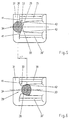
- the mode of action of means 27 for Inhibition of the movement of the actuator 3 is in one Principle sketch in Fig. 5 and 6 clarified.
- the passage opening 29 is of two conical ones Guide surfaces 30, 30 ', for example on the inner wall 31 of the Housing 2 are molded, formed. Because of the non-parallel, has the conical shape of the two guide surfaces 30, 30 ' Through opening 29 a narrowest point 32, the narrowest point 32nd a slightly smaller width than the largest cross section of the pin 28 having.
- the slopes 41, 42 are the narrowest on both sides Point 32 formed differently steep, the steeper Slant 41 the pin 28 in the unactuated position of the Actuator 3 is facing.
- the pin 28 also has asymmetrical cross-sectional profile with two sides 33, 34 on the each have different curvatures. The page 33 with the smaller curvature is in the unactuated position of the Contact system 8 facing the passage opening 29 and the side 34 the passage opening 29 faces away with the larger curvature.
- the housing 2 consists of two Housing parts, namely from a base 35 and a cover 36.
- Das Contact system 8, 8 ', the connecting parts 20, 21 and the guide for the Actuator 3 with plunger 4 are received in the base 35.
- the Pin 28 for the means 27 to inhibit the movement of the Actuator 3 is located on the cam control 17 and is thus also assigned to the base 35, while the guide surfaces 30, 30 'for the passage opening 29 preferably on the inner wall 31 of the lid 36 are located.
- Through tongue and groove connections 37, all around the base 35 and cover 36 all around are arranged, form the transition column between the two Housing parts 35, 36 a kind of labyrinth. This will make one Extensive dustproofness of the housing interior 5 also on these Transition columns achieved.
- the contact system is also suitable for switches with a according to the position of movement of the actuator adjustable electronics, for example for speed control of the power tool.
- a pivotable Actuator may be provided, this on a plunger, Slider or the like can act for the cam control.
- the lever arm of the switch contact is actuated Position of the contact system deviates from the parallel to Direction of movement of the plunger or slide and thus deviating from the parallel to the direction of movement of the cam control.
- a switch according to the invention can not only in Power tools are used, but can also be used in Garden tools, household appliances or the like. Find use.
Landscapes
- Rotary Switch, Piano Key Switch, And Lever Switch (AREA)
- Push-Button Switches (AREA)
Applications Claiming Priority (2)
| Application Number | Priority Date | Filing Date | Title |
|---|---|---|---|
| DE19651872A DE19651872A1 (de) | 1996-12-13 | 1996-12-13 | Elektrischer Schalter |
| DE19651872 | 1996-12-13 |
Publications (3)
| Publication Number | Publication Date |
|---|---|
| EP0848400A2 true EP0848400A2 (fr) | 1998-06-17 |
| EP0848400A3 EP0848400A3 (fr) | 1999-05-06 |
| EP0848400B1 EP0848400B1 (fr) | 2004-02-11 |
Family
ID=7814590
Family Applications (1)
| Application Number | Title | Priority Date | Filing Date |
|---|---|---|---|
| EP97121282A Expired - Lifetime EP0848400B1 (fr) | 1996-12-13 | 1997-12-04 | Interrupteur électrique |
Country Status (2)
| Country | Link |
|---|---|
| EP (1) | EP0848400B1 (fr) |
| DE (2) | DE19651872A1 (fr) |
Family Cites Families (10)
| Publication number | Priority date | Publication date | Assignee | Title |
|---|---|---|---|---|
| DE1910165C3 (de) * | 1969-02-28 | 1980-02-28 | Preh, Elektrofeinmechanische Werke, Jakob Preh, Nachf. Gmbh & Co, 8740 Bad Neustadt | Zweipoliger Schiebeschalter |
| DE2558620C2 (de) * | 1975-12-24 | 1982-09-02 | J.& J. Marquardt, 7201 Rietheim-Weilheim | Elektrischer Schalter |
| US4061895A (en) * | 1976-01-21 | 1977-12-06 | Cutler-Hammer, Inc. | Higher rated double-pole trigger switch |
| GB1577924A (en) * | 1977-06-29 | 1980-10-29 | Arrow Hart Europe Ltd | Hand grip for a portable electric appliance |
| DE2838934C2 (de) * | 1978-09-07 | 1986-07-31 | J. & J. Marquardt, 7201 Rietheim-Weilheim | Elektrischer Schalter |
| DE3439469A1 (de) * | 1984-10-27 | 1986-05-07 | Rudolf Schadow Gmbh, 1000 Berlin | Druck- oder schiebetastenschalter |
| DE3713775C2 (de) * | 1987-04-24 | 1996-02-08 | Cherry Mikroschalter Gmbh | Tastenschalter |
| DE4130827A1 (de) * | 1991-09-17 | 1993-03-25 | Braun Ag | Elektrischer schalter |
| DE4418707A1 (de) * | 1994-05-28 | 1995-11-30 | Teves Gmbh Alfred | Schnappschalter mit gerader Bewegung des Schaltstücks sowie Schaltersystem hierzu |
| DE19508925A1 (de) * | 1995-03-13 | 1996-09-19 | Marquardt Gmbh | Elektrischer Schalter, insbesondere für Elektrohandwerkzeuge |
-
1996
- 1996-12-13 DE DE19651872A patent/DE19651872A1/de not_active Withdrawn
-
1997
- 1997-12-04 DE DE59711293T patent/DE59711293D1/de not_active Expired - Lifetime
- 1997-12-04 EP EP97121282A patent/EP0848400B1/fr not_active Expired - Lifetime
Also Published As
| Publication number | Publication date |
|---|---|
| EP0848400B1 (fr) | 2004-02-11 |
| EP0848400A3 (fr) | 1999-05-06 |
| DE59711293D1 (de) | 2004-03-18 |
| DE19651872A1 (de) | 1998-06-18 |
Similar Documents
| Publication | Publication Date | Title |
|---|---|---|
| EP1101231B1 (fr) | Commutateur electrique | |
| DE102016117783A1 (de) | Elektrischer Schalter | |
| DE102016117785A1 (de) | Elektrischer Schalter | |
| EP0708464B1 (fr) | Commutateur électrique | |
| DE102008036393A1 (de) | Steuergerät, insbesondere in der Art eines elektrischen Schalters für Elektrohandwerkzeuge | |
| EP0848400B1 (fr) | Interrupteur électrique | |
| DE3442173A1 (de) | Elektrischer schalter gedrungener bauart | |
| DE2643955A1 (de) | Elektrischer schnappschalter | |
| DE10217406B4 (de) | Elektrischer Schalter | |
| EP0157186B1 (fr) | Commutateur à curseur verrouillable | |
| EP0777246B1 (fr) | Interrupteur électrique | |
| DE10254275B4 (de) | Elektrischer Schalter | |
| DE10219558A1 (de) | Elektrischer Leistungsschalter mit einer Anschlussschiene und einem Lichtbogenhorn | |
| DE3402082A1 (de) | Elektrischer schnappschalter | |
| EP1298685B1 (fr) | Commutateur avec verrouillage des bornes | |
| WO1998010456A1 (fr) | Disjoncteur de surintensite | |
| DE10244371C1 (de) | Positionsschalter | |
| DE10217450B4 (de) | Elektrischer Schalter | |
| DE19509017C2 (de) | Stromschalter und Verfahren zur Herstellung desselben | |
| EP1414052B1 (fr) | Interrupteur de position à action brusque | |
| DE3511898A1 (de) | Schnappschalter | |
| DE2951582A1 (de) | Elektrischer schalter | |
| DE10254992A1 (de) | Elektrischer Schalter | |
| DE2526485A1 (de) | Elektrischer schalter | |
| EP0502336B1 (fr) | Commutateur miniature |
Legal Events
| Date | Code | Title | Description |
|---|---|---|---|
| PUAI | Public reference made under article 153(3) epc to a published international application that has entered the european phase |
Free format text: ORIGINAL CODE: 0009012 |
|
| AK | Designated contracting states |
Kind code of ref document: A2 Designated state(s): DE ES GB IT NL |
|
| AX | Request for extension of the european patent |
Free format text: AL;LT;LV;MK;RO;SI |
|
| PUAL | Search report despatched |
Free format text: ORIGINAL CODE: 0009013 |
|
| AK | Designated contracting states |
Kind code of ref document: A3 Designated state(s): AT BE CH DE DK ES FI FR GB GR IE IT LI LU MC NL PT SE |
|
| AX | Request for extension of the european patent |
Free format text: AL;LT;LV;MK;RO;SI |
|
| 17P | Request for examination filed |
Effective date: 19990715 |
|
| AKX | Designation fees paid |
Free format text: DE ES GB IT NL |
|
| 17Q | First examination report despatched |
Effective date: 20011030 |
|
| GRAP | Despatch of communication of intention to grant a patent |
Free format text: ORIGINAL CODE: EPIDOSNIGR1 |
|
| RBV | Designated contracting states (corrected) |
Designated state(s): CH DE ES GB IT LI NL |
|
| GRAS | Grant fee paid |
Free format text: ORIGINAL CODE: EPIDOSNIGR3 |
|
| GRAA | (expected) grant |
Free format text: ORIGINAL CODE: 0009210 |
|
| AK | Designated contracting states |
Kind code of ref document: B1 Designated state(s): CH DE ES GB IT LI NL |
|
| PG25 | Lapsed in a contracting state [announced via postgrant information from national office to epo] |
Ref country code: IT Free format text: LAPSE BECAUSE OF FAILURE TO SUBMIT A TRANSLATION OF THE DESCRIPTION OR TO PAY THE FEE WITHIN THE PRE;WARNING: LAPSES OF ITALIAN PATENTS WITH EFFECTIVE DATE BEFORE 2007 MAY HAVE OCCURRED AT ANY TIME BEFORE 2007. THE CORRECT EFFECTIVE DATE MAY BE DIFFERENT FROM THE ONE RECORDED.SCRIBED TIME-LIMIT Effective date: 20040211 Ref country code: GB Free format text: LAPSE BECAUSE OF FAILURE TO SUBMIT A TRANSLATION OF THE DESCRIPTION OR TO PAY THE FEE WITHIN THE PRESCRIBED TIME-LIMIT Effective date: 20040211 |
|
| REG | Reference to a national code |
Ref country code: GB Ref legal event code: FG4D Free format text: NOT ENGLISH |
|
| REG | Reference to a national code |
Ref country code: CH Ref legal event code: EP |
|
| REF | Corresponds to: |
Ref document number: 59711293 Country of ref document: DE Date of ref document: 20040318 Kind code of ref document: P |
|
| REG | Reference to a national code |
Ref country code: CH Ref legal event code: NV Representative=s name: KELLER & PARTNER PATENTANWAELTE AG |
|
| PG25 | Lapsed in a contracting state [announced via postgrant information from national office to epo] |
Ref country code: ES Free format text: LAPSE BECAUSE OF FAILURE TO SUBMIT A TRANSLATION OF THE DESCRIPTION OR TO PAY THE FEE WITHIN THE PRESCRIBED TIME-LIMIT Effective date: 20040522 |
|
| GBV | Gb: ep patent (uk) treated as always having been void in accordance with gb section 77(7)/1977 [no translation filed] |
Effective date: 20040211 |
|
| PLBE | No opposition filed within time limit |
Free format text: ORIGINAL CODE: 0009261 |
|
| STAA | Information on the status of an ep patent application or granted ep patent |
Free format text: STATUS: NO OPPOSITION FILED WITHIN TIME LIMIT |
|
| 26N | No opposition filed |
Effective date: 20041112 |
|
| REG | Reference to a national code |
Ref country code: CH Ref legal event code: PCAR Free format text: NEW ADDRESS: EIGERSTRASSE 2 POSTFACH, 3000 BERN 14 (CH) |
|
| PGFP | Annual fee paid to national office [announced via postgrant information from national office to epo] |
Ref country code: CH Payment date: 20151221 Year of fee payment: 19 |
|
| PGFP | Annual fee paid to national office [announced via postgrant information from national office to epo] |
Ref country code: NL Payment date: 20151221 Year of fee payment: 19 |
|
| PGFP | Annual fee paid to national office [announced via postgrant information from national office to epo] |
Ref country code: DE Payment date: 20170112 Year of fee payment: 20 |
|
| REG | Reference to a national code |
Ref country code: CH Ref legal event code: PL |
|
| REG | Reference to a national code |
Ref country code: NL Ref legal event code: MM Effective date: 20170101 |
|
| PG25 | Lapsed in a contracting state [announced via postgrant information from national office to epo] |
Ref country code: NL Free format text: LAPSE BECAUSE OF NON-PAYMENT OF DUE FEES Effective date: 20170101 |
|
| PG25 | Lapsed in a contracting state [announced via postgrant information from national office to epo] |
Ref country code: CH Free format text: LAPSE BECAUSE OF NON-PAYMENT OF DUE FEES Effective date: 20161231 Ref country code: LI Free format text: LAPSE BECAUSE OF NON-PAYMENT OF DUE FEES Effective date: 20161231 |
|
| REG | Reference to a national code |
Ref country code: DE Ref legal event code: R071 Ref document number: 59711293 Country of ref document: DE |