EP0848436A2 - Separatorenmaterial für alkalische Speicherbatterien - Google Patents
Separatorenmaterial für alkalische Speicherbatterien Download PDFInfo
- Publication number
- EP0848436A2 EP0848436A2 EP97117952A EP97117952A EP0848436A2 EP 0848436 A2 EP0848436 A2 EP 0848436A2 EP 97117952 A EP97117952 A EP 97117952A EP 97117952 A EP97117952 A EP 97117952A EP 0848436 A2 EP0848436 A2 EP 0848436A2
- Authority
- EP
- European Patent Office
- Prior art keywords
- fibers
- separator material
- thick
- storage batteries
- alkaline storage
- Prior art date
- Legal status (The legal status is an assumption and is not a legal conclusion. Google has not performed a legal analysis and makes no representation as to the accuracy of the status listed.)
- Withdrawn
Links
Images

Classifications
-
- H—ELECTRICITY
- H01—ELECTRIC ELEMENTS
- H01M—PROCESSES OR MEANS, e.g. BATTERIES, FOR THE DIRECT CONVERSION OF CHEMICAL ENERGY INTO ELECTRICAL ENERGY
- H01M50/00—Constructional details or processes of manufacture of the non-active parts of electrochemical cells other than fuel cells, e.g. hybrid cells
- H01M50/40—Separators; Membranes; Diaphragms; Spacing elements inside cells
- H01M50/409—Separators, membranes or diaphragms characterised by the material
- H01M50/44—Fibrous material
-
- H—ELECTRICITY
- H01—ELECTRIC ELEMENTS
- H01M—PROCESSES OR MEANS, e.g. BATTERIES, FOR THE DIRECT CONVERSION OF CHEMICAL ENERGY INTO ELECTRICAL ENERGY
- H01M50/00—Constructional details or processes of manufacture of the non-active parts of electrochemical cells other than fuel cells, e.g. hybrid cells
- H01M50/40—Separators; Membranes; Diaphragms; Spacing elements inside cells
- H01M50/409—Separators, membranes or diaphragms characterised by the material
- H01M50/411—Organic material
- H01M50/414—Synthetic resins, e.g. thermoplastics or thermosetting resins
- H01M50/417—Polyolefins
-
- H—ELECTRICITY
- H01—ELECTRIC ELEMENTS
- H01M—PROCESSES OR MEANS, e.g. BATTERIES, FOR THE DIRECT CONVERSION OF CHEMICAL ENERGY INTO ELECTRICAL ENERGY
- H01M2300/00—Electrolytes
- H01M2300/0002—Aqueous electrolytes
- H01M2300/0014—Alkaline electrolytes
-
- Y—GENERAL TAGGING OF NEW TECHNOLOGICAL DEVELOPMENTS; GENERAL TAGGING OF CROSS-SECTIONAL TECHNOLOGIES SPANNING OVER SEVERAL SECTIONS OF THE IPC; TECHNICAL SUBJECTS COVERED BY FORMER USPC CROSS-REFERENCE ART COLLECTIONS [XRACs] AND DIGESTS
- Y02—TECHNOLOGIES OR APPLICATIONS FOR MITIGATION OR ADAPTATION AGAINST CLIMATE CHANGE
- Y02E—REDUCTION OF GREENHOUSE GAS [GHG] EMISSIONS, RELATED TO ENERGY GENERATION, TRANSMISSION OR DISTRIBUTION
- Y02E60/00—Enabling technologies; Technologies with a potential or indirect contribution to GHG emissions mitigation
- Y02E60/10—Energy storage using batteries
Definitions
- the present invention relates to an improvement in a separator material for alkaline storage batteries, more specifically a separator material excellent in electrolyte absorption and gas-permeability.
- sealed alkaline storage batteries are required to have a higher discharge capacity, a longer cycle life, and a rapid chargeability.
- the capacity density and cycle life of the battery are greatly influenced by the amount of the alkaline electrolyte contained in the battery.
- an electrolyte is contained in larger amounts from the aspects of the discharge capacity and the cycle life of battery.
- a smaller amount of electrolyte is better in order not to deteriorate but to improve the gas-permeability of the separator.
- the amount of electrolyte is limited in a sealed battery of a given size because the electrolyte can exist only in a state of being impregnated and retained in the electrodes and the separator of a battery and cannot exist in a free state.
- the electric resistance of the separator increases, which results in a decrease in the discharge voltage of the battery.
- the starvation of electrolyte in the separator is greatly influenced by the electrolyte absorption of the nickel positive electrode.
- the discharge reaction is also inhibited by the starvation of electrolyte at the separator and the discharge capacity of the battery decreases.
- the separator material plays an important role in realizing the above-mentioned battery performances.
- Essential factors required for the separator material are low electric resistance, excellent alkali-resistance and oxidation resistance.
- the separator materials are also required to have preferable electrolyte absorption and appropriate gas-permeable properties and to maintain these properties for a long term.
- the segmented composite fibers have a filament cross-section comprising a plurality of resin materials so arranged that one resin material is between the other resin materials, and are spun so as to be longitudinally divided into a plurality of ultra-thin individual fibers by a fluid stream or the like.
- the non-woven fabric sheet comprising polyolefin resin fibers, such as polypropylene or the like, produced by the conventional melt-blow process has a problem of unsatisfactory tensile strength of the individual fibers, which causes the problem of lacking a mechanical strength as a separator material which is necessary during the battery production process.
- another non-woven fabric sheet comprises the segmented composite fibers which have been processed into a state of non-woven fabric in a dry or wet process whereby the individual fibers are entangled with each other.
- the non-woven fabric sheet thus configured has a greater tensile strength than the fabric produced by the melt-blow process and can solve the problem encountered with one produced by the melt-blow process, because the individual fibers have been drawn at the stage of spinning.
- the non-woven fabric sheet produced by this process is insufficient in mechanical strength and thus lacks the so-called "nerve". This leads to a problem of lacking the mechanical strength as a separator material which is necessary at the time of rolling it up with the electrodes in a spiral fashion during the battery production process.
- Another object of the present invention is to provide a separator material which gives such batteries that do not raise their inner pressure and have a long cycle life, when applied to an alkaline storage battery of high capacity density.
- the present invention provides a separator material for alkaline storage batteries comprising a non-woven fabric sheet of a mixture of thin polyolefin resin fibers having a filament diameter ranging from 2 ⁇ m to 8 ⁇ m with thick polyolefin resin fibers having a filament diameter ranging from 9 ⁇ m to 15 ⁇ m, wherein a ratio by weight of the thin resin fibers to the thick resin fibers is between 90:10 and 50:50, a basis weight of the non-woven fabric sheet is ranging from 40 g/m 2 to 70 g/m 2 and a gas-permeability is ranging from 3 cc/cm 2 ⁇ sec. to 14 cc/cm 2 ⁇ sec., and the thin and thick resin fibers are surface-treated to have a hydrophilic property.
- the non-woven fabric sheet configured with the thin fibers as a main ingredient and mixing the thick fibers with the thin fibers in a preferable ratio, it is possible to provide a separator material for alkaline storage batteries having a preferable electrolyte absorption property and gas-permeability as well as a sufficient tensile strength and high stiffness, the so-called "nerve”.
- Processes for imparting the surfaces of the individual resin fibers with the hydrophilic property are preferably performed by graft polymerization with acrylic acid or by sulfonation.
- Qualitative requirement of the thick resin fibers to be mixed with the thin resin fibers may be any of polyolefin resin containing ethylene component, and can arbitrarily selected from fibers consisting mainly of polypropylene and containing polyethylene, core-sheath fibers produced by coating core fibers of polypropylene with sheathes of polyethylene, and the like.
- the non-woven fabric is comprised of these fibers as a main ingredient, small amounts of another fibers containing no ethylene component, for instance, polypropylene fibers may be mixed therewith.
- the thick resin fibers By mixing the thick resin fibers with the thin resin fibers in particular, it is possible to enhance the tensile strength and the stiffness, the so-called “nerve” of the separator of the non-woven fabric sheet configured with the fibers, to facilitate its handling, and to improve the productivity of the batteries. In addition, it is also possible to control the gas-permeability and electrolyte absorption of the separator material with ease, and maintain the battery inner pressure low enough, even when the battery has a higher discharge capacity density, whereby a longer cycle life of the battery can be realized.
- FIG. 1 is an enlarged schematic view showing the separator material in accordance with an embodiment of the present invention which comprises a non-woven fabric sheet of the thin fibers and the thick fibers wherein the surfaces of the individual fibers are treated by graft polymerization with acrylic acid.
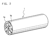
- FIG. 2 is an enlarged schematic perspective view of the segmented composite fiber used for the separator material.
- the separator material in accordance with the present invention comprises a non-woven fabric sheet of a mixture of thin polyolefin resin fibers and thick polyolefin resin fibers in a predetermined proportion, wherein a basis weight of the non-woven fabric sheet is 40 to 70 g/m 2 and gas permeability is 3 to 14 cc/cm 2 ⁇ sec.
- This configuration ensures not only the physical strength of the separator material, which is a requisite for the battery production process, but also the electrolyte absorption and gas-permeability properties of the separator material, which are requisites for a sealed storage battery.
- hydrophilic groups are introduced onto the surfaces of the individual fibers in accordance with the present invention. It is preferable to introduce the hydrophilic groups onto the surfaces of the individual fibers by graft polymerization with a hydrophilic monomer having a carboxyl group. This imparts the separator material with a long-term hydrophilic property.
- the separator material is imparted with the long-term hydrophilic property by graft polymerization of the surfaces of the polyolefin resin fibers which have an insufficient hydrophilic property with acrylic acid, or by sulfonation of the parts of the fibers having ethylene component by immersing the fibers in fuming sulfuric acid or concentrated sulfuric acid, thereby to modify the parts of ethylene component with sulfone groups.
- any other methods such as treatment with a surface active agent of the fiber surfaces, treatment by corona discharge and the like may also be used in addition to the above-mentioned treatments.
- the thin resin fibers 1 which constitute the separator material shown in FIG.1 are segmented composite fibers of polypropylene and polyethylene.
- the thick resin fibers 2 are core-sheath fibers comprising core fibers of polypropylene and sheathes of polyethylene for covering the core polypropylene fibers.
- polypropylene fibers may be added thereto.
- the separator material by taking, as its specific examples, a nickel-metal hydride storage battery configured with the separator material comprising the non-woven fabric sheet of polypropylene resin fibers whose surfaces are treated by graft polymerization with acrylic acid.
- Such non-woven fabric sheet of polypropylene resin fibers is produced in compliance with the following procedures. First, segmented composite fibers each having a cross-section where polyethylene components and polypropylene components are alternately arranged as shown in FIG. 2 are prepared. The segmented composite fibers are divided into four polypropylene fibers 1a and four polyethylene fibers 1b by the subsequent segmentation treatment. Nominal filament diameters of the individual fibers 1a and 1b are 4.7 ⁇ m.
- core-sheath fibers which comprise cores of polypropylene resin and sheathes of polyethylene resin covering the cores add which have nominal filament diameters of 9 ⁇ m are also prepared.
- the nominal filament diameters of the individual fibers 1a and 1b having a non-circular cross-section are defined to represent the larger diameters of the cross-sections.
- a primary non-woven fabric sheet is produced by dispersing the thick fibers and the segmented composite fibers in an aqueous dispersing medium containing no binding agent, and scooping up the dispersed fibers with a wire cloth from the dispersion. Subsequently, the primary non-woven fabric sheet is treated in a water stream to separate the segmented composite fibers and intermingle the individual fibers with each other. This produces a secondary non-woven fabric sheet. In this manner, the non-woven fabric sheet which has a basis weight and a thickness of 55 g/m 2 and 180 ⁇ m, respectively, is obtained. In this example, the proportion by weight of the above-mentioned thin fibers to the thick fibers is adjusted to 80:20.
- a solution comprising 20 wt% of acrylic acid, 65 wt% of distilled water, 0.5 wt% of benzophenone, 0.3 wt% of Mohr's salt, 13.7 wt% of methoxyethanol and 0.5 wt% of nonionic surface active agent is prepared.
- the above-mentioned non-woven fabric sheet is immersed for 10 minutes. In order to exclude the influence of oxygen during the subsequent polymerization as much as possible, this solution has previously been de-oxidized with nitrogen prior to the immersion.
- the immersed non-woven fabric sheet is subjected to the graft polymerization with acrylic acid by irradiating both surfaces of the non-woven fabric sheet with ultraviolet ray under a de-oxidized atmosphere using two low-pressure mercury lamps (output: 110 watt), each placed at a 5 cm distance from the surfaces of the non-woven fabric sheet.
- the unreacted acrylic acid and other components remaining on the non-woven fabric sheet are removed by washing it with distilled water at 60 °C. Subsequent drying and calendering of the fabric sheet produces a separator material having a basis weight of 60 g/m 2 and a thickness of 120 ⁇ m.
- the calculated modification amount (graft ratio) of the above-mentioned separator material is 9 %.
- Evaluation of the strength in "nerve" of the separator material is made by measuring its stiffness representing the bending repulsion on a Gurley-type tester in compliance with a method stipulated in 6.20. 1. A of JIS L1096-1979.
- Evaluation of the gas-permeability of the separator material is made by measuring its gas-permeability at a pressure difference of 12.7 mm aq. on a Frazir type gas-permeation tester in compliance with a method stipulated in 6.27. 1. A of JIS L1096-1979.
- the electrolyte absorption property of the separator material is evaluated by measuring its electrolyte absorption ratio under pressure. That of the polypropylene non-woven fabric sheet subjected to the graft polymerization with acrylic acid is evaluated in the following procedures.
- the stiffness representing the strength of "nerve”, the gas-permeability and the electrolyte absorption ratio under pressure of the above-mentioned separator material are found to be 5.0 mg, 45 cc/cm 2 ⁇ sec. and 25 %, respectively.
- the separator "i" comprising only the thick fibers had high stiffness because of its strong “nerve”, and the gas-permeation rate was large because the pore sizes became large.
- sealed alkaline storage batteries were produced by using the above-mentioned separators "a” to "i” in the following procedure.
- nickel hydroxide powder as an active material 100 parts by weight of nickel hydroxide powder as an active material was kneaded with 6 parts by weight of cobalt hydroxide and water to prepare a paste which was then filled into a foamed nickel porous substrate, and subsequently dried and pressed.
- the pressed substrate was immersed in an aqueous dispersion of fluorocarbon resin, dried, and cut to a predetermined size, which gave a positive electrode.
- a hydrogen storage alloy having a composition represented by the formula MmNi 3.55 Mn 0.4 Al 0.3 Co 0.75 (Mm is a mixture of rare earth elements) having a crystal structure of CaCu 5 type was used.
- This alloy was pulverized in a ball mill into fine powders having an average particle diameter of about 30 ⁇ m which were then immersed in an aqueous solution of KOH at 80 °C and washed with water.
- a paste was obtained by mixing this hydrogen storage alloy powder with an aqueous dispersion of stylene-butadiene rubber, carboxymethyl cellulose, carbon powder and water, and the obtained paste was applied onto a punched steel sheet elated with nickel. After dried, the applied punched steel sheet was pressed and cut to a predetermined size. This gave a negative electrode.
- the battery case After injecting an appropriate amount of electrolyte comprising an aqueous solution composed mainly of KOH and containing a small amount of NaOH and LiOH into the battery case, the battery case was sealed with a sealing plate and a gasket, thereby to obtain a sealed battery having a discharge capacity of 1,800 mAh.
- the batteries A to I configured with the separator materials "a" to "i” listed in Table 1 at an ambient temperature of 20 °C were subjected to an inner pressure test and a cycle life test.
- Conditions for the inner pressure test included charging at a current of 1.8 A at an ambient temperature of 20 °C for 72 minutes.
- Conditions for the cycle life test included repeated charging at a current of 1.8 A for 72 minutes and discharging at a current of 1.8 A until the terminal voltage dropped to 1.0 V at an ambient temperature of 20 °C, and the cycle life of the tested battery was determined by the number of cycles up to the time point when the discharge capacity decreased to 60% of the initial discharge capacity.
- the separator material may sometimes be transferred while it is shifted aside during the process of transferring from the start of rolling-up to the electrode group configuration step in combining the electrode plates with the separator material in the electrode group configuring unit. Consequently, in the spirally rolled-up electrode group, the axial positions of the electrode plates may sometimes shift from that of the separator, and the electrode plates project over the separator. This causes the increase of the leakage-associated defective.
- Table 2 summarizes the results of the leakage-associated defective ratio during the electrode group configuration by mass production, the battery inner pressures and the cycle lives of the respective batteries A to I.
- Battery Leakage defective resulting from the rolling-up shift during the electrode group configuration (%) Battery inner pressure (kg/cm 2 ) Cycle life (cycles)
- Example 1 A 0% 5.5 420
- Example 2 B 0% 4.0 380
- Example 3 C 0% 3.8 290
- Example 4 D 0% 3.5 270
- Example 6 F 0% 7.5 430 Comparative example 1 G 20% 12.0 250 Comparative example 2 H 30% 15.0 230 Comparative example 3 I 0% 3.0 200
- the batteries A to F had a higher electrolyte absorption property as compared with that of the battery I, they were excellent in cycle life characteristics. Although the batteries G and H were excellent in electrolyte absorption property, their cycle life characteristics were low because their inner pressure characteristics were inferior. Since the batteries A, B, E and F, in particular, were excellent in both gas-permeability and electrolyte absorption property, they demonstrated a small increase in inner pressure and had cycle life characteristics of not less than 300 cycles. These confirmed that they had no problem in practical use.
- the separator material has a basis weight of 40 g/m 2 to 70 g/m 2 and a thickness of 50 ⁇ m to 180 ⁇ m. If the basis weight is smaller than 40 g/m 2 , it is difficult to secure necessary stiffness, even if the mixing ratio of the thick fibers is large. In contrast, if the basis weight is larger than 70 g/m 2 , or if the thickness is not more than 50 ⁇ m, it is difficult to secure appropriate gas-permeability. In addition, if the thickness is not less than 180 ⁇ m, it is difficult to realize a higher capacity density of the battery because space occupied by the separator increases with the thicker separator material.
- Such a tendency as appreciated in the treatment for imparting hydrophilic property by the graft polymerization with acrylic acid is not limited to the graft polymerization and also appreciated in the treatment by sulfonation, by corona discharge or with a surface active agent.
- the treatment by sulfonation is performed under the following conditions.
- the non-woven fabric sheet is immersed in 20% fuming sulfuric acid at 35 °C for about 20 minutes, followed by washing with water and drying.
- the amount of the sulfone groups to be introduced into the fibers is preferably in a range of 0.1 milli equivalent/g to 1 milli equivalent/g.
- the treatment by corona discharge is performed under the following conditions.
- An electrode which has a width of 20 mm and a length of 600 mm and is connected to a high voltage power source with an output of 30 kV, and a counter electrode of the same size which has a layer coated with a dielectric substance are installed with a gap of 3.2 mm therebetween, through which the belt-like non-woven fabric sheet can travel. While the non-woven fabric sheet is transferred through the gap, a corona discharge is effected between both electrodes so that the total energy irradiated on one face of the non-woven fabric is 17.5 kW/m 2 , thereby to treat the surfaces of the fibers of the non-woven fabric sheet with the ozone generated during the discharge. From the results of the evaluation of the separator material thus treated, a similar technical advantage to that of the above-mentioned separator was obtained.
- Treatment with surface active agent was performed as follows:
- the above-mentioned non-woven fabric sheet was immersed in an aqueous solution containing a nonionic surface active agent and dried to prepare a non-woven fabric sheet of which surfaces are applied with the surface active agent of 0.1 wt% of the separator.
- the separator material in accordance with the present invention can also be used in any other alkaline storage batteries comprising any of the nickel hydroxide positive electrode or the hydrogen storage alloy negative electrode, such as nickel-zinc storage batteries, manganese dioxide-metal hydride storage batteries and the like, with a similar technical advantage.
Landscapes
- Chemical & Material Sciences (AREA)
- Chemical Kinetics & Catalysis (AREA)
- Electrochemistry (AREA)
- General Chemical & Material Sciences (AREA)
- Cell Separators (AREA)
- Secondary Cells (AREA)
- Artificial Filaments (AREA)
- Nonwoven Fabrics (AREA)
Applications Claiming Priority (2)
| Application Number | Priority Date | Filing Date | Title |
|---|---|---|---|
| JP33330296A JP3221337B2 (ja) | 1996-12-13 | 1996-12-13 | アルカリ蓄電池用セパレータ |
| JP333302/96 | 1996-12-13 |
Publications (2)
| Publication Number | Publication Date |
|---|---|
| EP0848436A2 true EP0848436A2 (de) | 1998-06-17 |
| EP0848436A3 EP0848436A3 (de) | 1999-05-26 |
Family
ID=18264592
Family Applications (1)
| Application Number | Title | Priority Date | Filing Date |
|---|---|---|---|
| EP97117952A Withdrawn EP0848436A3 (de) | 1996-12-13 | 1997-10-16 | Separatorenmaterial für alkalische Speicherbatterien |
Country Status (3)
| Country | Link |
|---|---|
| EP (1) | EP0848436A3 (de) |
| JP (1) | JP3221337B2 (de) |
| CN (1) | CN1089192C (de) |
Cited By (9)
| Publication number | Priority date | Publication date | Assignee | Title |
|---|---|---|---|---|
| EP0874409A3 (de) * | 1997-04-23 | 1999-05-26 | Matsushita Electric Industrial Co., Ltd. | Alkalischer Akkumulator |
| EP0921580A1 (de) * | 1997-11-25 | 1999-06-09 | Sanyo Electric Co., Ltd. | Herstellungsverfahren von alkalischer Speicherzelle |
| EP0975032A1 (de) * | 1998-07-21 | 2000-01-26 | Matsushita Electric Industrial Co., Ltd. | Alkalische Speicherbatterie mit einem Separatorvlies aus Polyolefinfasern |
| EP1079448A4 (de) * | 1999-02-08 | 2002-05-02 | Japan Vilene Co Ltd | Separator für alkalische batterie und herstellungsverfahren |
| EP1179864A3 (de) * | 2000-08-10 | 2003-12-10 | Japan Vilene Company, Ltd. | Batterieseparator |
| US6849702B2 (en) | 1999-02-26 | 2005-02-01 | Robert W. Callahan | Polymer matrix material |
| US7790306B2 (en) * | 2006-03-24 | 2010-09-07 | Sanyo Electric Co., Ltd. | Nickel hydrogen storage battery |
| CN103035865A (zh) * | 2011-09-30 | 2013-04-10 | 松下蓄电池(沈阳)有限公司 | 电池用隔板结构体及具有该隔板结构体的铅蓄电池 |
| US20140349194A1 (en) * | 2013-05-27 | 2014-11-27 | Toyota Boshoku Kabushiki Kaisha | Separator and method for manufacturing the separator |
Families Citing this family (9)
| Publication number | Priority date | Publication date | Assignee | Title |
|---|---|---|---|---|
| JP3510156B2 (ja) * | 1999-06-25 | 2004-03-22 | 大和紡績株式会社 | 電池セパレータ並びに電池 |
| JP4846083B2 (ja) * | 2000-05-12 | 2011-12-28 | パナソニック株式会社 | 蓄電池用電極の製造方法 |
| JP2002313306A (ja) * | 2001-04-06 | 2002-10-25 | Isao Matsumoto | 電池用セパレータの製造方法、電池用セパレータ及びそれを用いたアルカリ蓄電池 |
| CN102656719B (zh) * | 2009-11-27 | 2015-05-27 | 株式会社Lg化学 | 隔膜的制备方法、由该方法制备的隔膜和含有该隔膜的电化学装置 |
| CN102496464B (zh) * | 2011-12-09 | 2014-01-15 | 莱州联友金浩新型材料有限公司 | 超级电容电池隔膜、其制备方法和应用 |
| EP3379601B1 (de) * | 2017-03-21 | 2020-05-13 | Kabushiki Kaisha Toshiba | Sekundärbatterie, batteriepack und fahrzeug |
| JP6904298B2 (ja) * | 2018-04-05 | 2021-07-14 | 株式会社豊田自動織機 | アルカリ蓄電池及びその製造方法 |
| CN108677384B (zh) * | 2018-05-29 | 2020-06-26 | 中原工学院 | 一种水平分支结构的熔喷非织造复合材料及其制备方法 |
| CN113083041B (zh) * | 2020-01-09 | 2022-07-01 | 杭州科百特科技有限公司 | 一种用于层析的纳米纤维膜及其制备工艺 |
Family Cites Families (5)
| Publication number | Priority date | Publication date | Assignee | Title |
|---|---|---|---|---|
| JPS55105962A (en) * | 1979-01-18 | 1980-08-14 | Matsushita Electric Ind Co Ltd | Separator for cell |
| JP2982218B2 (ja) * | 1990-05-31 | 1999-11-22 | 松下電器産業株式会社 | 電池用セパレータ |
| JP2984561B2 (ja) * | 1994-11-15 | 1999-11-29 | 大和紡績株式会社 | 電池セパレータおよびその製造方法 |
| KR100299559B1 (ko) * | 1994-12-28 | 2001-09-03 | 야마모토 카즈모토 | 전지세퍼레이터용습식부직포와그의제조방법및밀폐형2차전지 |
| JPH103937A (ja) * | 1996-06-14 | 1998-01-06 | Shin Kobe Electric Mach Co Ltd | 密閉形アルカリ蓄電池 |
-
1996
- 1996-12-13 JP JP33330296A patent/JP3221337B2/ja not_active Expired - Lifetime
-
1997
- 1997-10-16 EP EP97117952A patent/EP0848436A3/de not_active Withdrawn
- 1997-10-31 CN CN97121292A patent/CN1089192C/zh not_active Expired - Lifetime
Cited By (14)
| Publication number | Priority date | Publication date | Assignee | Title |
|---|---|---|---|---|
| EP0874409A3 (de) * | 1997-04-23 | 1999-05-26 | Matsushita Electric Industrial Co., Ltd. | Alkalischer Akkumulator |
| US6130008A (en) * | 1997-04-23 | 2000-10-10 | Matsushita Electric Industrial Co., Ltd. | Alkaline storage battery |
| EP0921580A1 (de) * | 1997-11-25 | 1999-06-09 | Sanyo Electric Co., Ltd. | Herstellungsverfahren von alkalischer Speicherzelle |
| EP0975032A1 (de) * | 1998-07-21 | 2000-01-26 | Matsushita Electric Industrial Co., Ltd. | Alkalische Speicherbatterie mit einem Separatorvlies aus Polyolefinfasern |
| USRE41203E1 (en) | 1999-02-08 | 2010-04-06 | Japan Vilene Company, Ltd. | Alkaline battery separator and process for producing the same |
| US6607859B1 (en) | 1999-02-08 | 2003-08-19 | Japan Vilene Company, Ltd. | Alkaline battery separator and process for producing the same |
| EP1079448A4 (de) * | 1999-02-08 | 2002-05-02 | Japan Vilene Co Ltd | Separator für alkalische batterie und herstellungsverfahren |
| US6849702B2 (en) | 1999-02-26 | 2005-02-01 | Robert W. Callahan | Polymer matrix material |
| EP1179864A3 (de) * | 2000-08-10 | 2003-12-10 | Japan Vilene Company, Ltd. | Batterieseparator |
| US7402539B2 (en) | 2000-08-10 | 2008-07-22 | Japan Vilene Co., Ltd. | Battery separator |
| US7790306B2 (en) * | 2006-03-24 | 2010-09-07 | Sanyo Electric Co., Ltd. | Nickel hydrogen storage battery |
| CN103035865A (zh) * | 2011-09-30 | 2013-04-10 | 松下蓄电池(沈阳)有限公司 | 电池用隔板结构体及具有该隔板结构体的铅蓄电池 |
| CN103035865B (zh) * | 2011-09-30 | 2015-06-10 | 松下蓄电池(沈阳)有限公司 | 电池用隔板结构体及具有该隔板结构体的铅蓄电池 |
| US20140349194A1 (en) * | 2013-05-27 | 2014-11-27 | Toyota Boshoku Kabushiki Kaisha | Separator and method for manufacturing the separator |
Also Published As
| Publication number | Publication date |
|---|---|
| CN1185043A (zh) | 1998-06-17 |
| EP0848436A3 (de) | 1999-05-26 |
| JPH10172533A (ja) | 1998-06-26 |
| JP3221337B2 (ja) | 2001-10-22 |
| CN1089192C (zh) | 2002-08-14 |
Similar Documents
| Publication | Publication Date | Title |
|---|---|---|
| EP0848436A2 (de) | Separatorenmaterial für alkalische Speicherbatterien | |
| EP1689008B1 (de) | Batterieseparator und diesen enthaltende Batterie | |
| EP1085589B1 (de) | Batterieseparator | |
| US6772489B2 (en) | Collector for alkaline secondary battery, method for making the same, and alkaline secondary battery using the same | |
| EP1047140B1 (de) | Batterieseparator, Herstellungsverfahren und alkalische Batterie | |
| EP0710994A2 (de) | Batterieseparator aus Vliesstoff, enthaltend gepfropfte Polyolefinfasern | |
| US5681673A (en) | Alkaline secondary battery | |
| US6130008A (en) | Alkaline storage battery | |
| EP1073131B1 (de) | Separator für alkalische Batterie und Verfahren zur Herstellung | |
| US6468687B1 (en) | Alkaline storage battery with reinforced separators | |
| US6033803A (en) | Hydrophilic electrode for an alkaline electrochemical cell, and method of manufacture | |
| EP0921580A1 (de) | Herstellungsverfahren von alkalischer Speicherzelle | |
| EP0975032A1 (de) | Alkalische Speicherbatterie mit einem Separatorvlies aus Polyolefinfasern | |
| EP1022790A2 (de) | Alkalische Speicherbatterie und Herstellungsverfahren | |
| JP2000106162A (ja) | アルカリ電池用セパレ―タ及びその製造方法 | |
| JP3436058B2 (ja) | アルカリ蓄電池 | |
| KR100389123B1 (ko) | 알카리2차전지용 세퍼레이터 및 이의 제조방법 | |
| JP2002367591A (ja) | アルカリ電池用セパレータ | |
| JP3031156B2 (ja) | アルカリ蓄電池 | |
| JP2002110129A (ja) | 電池用セパレータおよびニッケル−水素蓄電池 | |
| JP2004296356A (ja) | 電池用セパレータ及び電池 | |
| JP4468645B2 (ja) | 電池用セパレータ及び電池 | |
| JPH10284116A (ja) | アルカリ蓄電池 | |
| JP2000021400A (ja) | 密閉型ニッケル−水素蓄電池 | |
| JPH04259752A (ja) | ペースト式ニッケル極の製造方法 |
Legal Events
| Date | Code | Title | Description |
|---|---|---|---|
| PUAI | Public reference made under article 153(3) epc to a published international application that has entered the european phase |
Free format text: ORIGINAL CODE: 0009012 |
|
| 17P | Request for examination filed |
Effective date: 19971016 |
|
| AK | Designated contracting states |
Kind code of ref document: A2 Designated state(s): DE FR GB |
|
| PUAL | Search report despatched |
Free format text: ORIGINAL CODE: 0009013 |
|
| AK | Designated contracting states |
Kind code of ref document: A3 Designated state(s): AT BE CH DE DK ES FI FR GB GR IE IT LI LU MC NL PT SE |
|
| AKX | Designation fees paid |
Free format text: DE FR GB |
|
| 17Q | First examination report despatched |
Effective date: 20010509 |
|
| STAA | Information on the status of an ep patent application or granted ep patent |
Free format text: STATUS: THE APPLICATION IS DEEMED TO BE WITHDRAWN |
|
| 18D | Application deemed to be withdrawn |
Effective date: 20010919 |