EP0848452A1 - Module de raccordement à bornes de connexion interconnectables par pièce(s) conductrice(s) mobile(s) - Google Patents
Module de raccordement à bornes de connexion interconnectables par pièce(s) conductrice(s) mobile(s) Download PDFInfo
- Publication number
- EP0848452A1 EP0848452A1 EP97402989A EP97402989A EP0848452A1 EP 0848452 A1 EP0848452 A1 EP 0848452A1 EP 97402989 A EP97402989 A EP 97402989A EP 97402989 A EP97402989 A EP 97402989A EP 0848452 A1 EP0848452 A1 EP 0848452A1
- Authority
- EP
- European Patent Office
- Prior art keywords
- housing
- extensions
- operating
- conductive
- level
- Prior art date
- Legal status (The legal status is an assumption and is not a legal conclusion. Google has not performed a legal analysis and makes no representation as to the accuracy of the status listed.)
- Granted
Links
- 239000004020 conductor Substances 0.000 claims description 14
- 210000001520 comb Anatomy 0.000 claims description 10
- 238000006073 displacement reaction Methods 0.000 claims description 7
- 239000011810 insulating material Substances 0.000 claims description 4
- 238000003780 insertion Methods 0.000 claims description 3
- 230000037431 insertion Effects 0.000 claims description 3
- 230000014759 maintenance of location Effects 0.000 claims description 3
- 230000000295 complement effect Effects 0.000 claims 1
- 230000009977 dual effect Effects 0.000 description 2
- 238000009434 installation Methods 0.000 description 2
- 239000002184 metal Substances 0.000 description 2
- 230000000694 effects Effects 0.000 description 1
- 239000012212 insulator Substances 0.000 description 1
- 238000004519 manufacturing process Methods 0.000 description 1
- 239000000463 material Substances 0.000 description 1
- 238000000465 moulding Methods 0.000 description 1
- 238000000926 separation method Methods 0.000 description 1
Images



Classifications
-
- H—ELECTRICITY
- H01—ELECTRIC ELEMENTS
- H01R—ELECTRICALLY-CONDUCTIVE CONNECTIONS; STRUCTURAL ASSOCIATIONS OF A PLURALITY OF MUTUALLY-INSULATED ELECTRICAL CONNECTING ELEMENTS; COUPLING DEVICES; CURRENT COLLECTORS
- H01R9/00—Structural associations of a plurality of mutually-insulated electrical connecting elements, e.g. terminal strips or terminal blocks; Terminals or binding posts mounted upon a base or in a case; Bases therefor
- H01R9/22—Bases, e.g. strip, block, panel
- H01R9/24—Terminal blocks
- H01R9/26—Clip-on terminal blocks for side-by-side rail- or strip-mounting
- H01R9/2625—Clip-on terminal blocks for side-by-side rail- or strip-mounting with built-in electrical component
- H01R9/2633—Clip-on terminal blocks for side-by-side rail- or strip-mounting with built-in electrical component with built-in switch
Definitions
- connection module in particular of the block type. junction, comprising connection terminals interconnectable by through moving conductive parts. which are housed in the module and which can be operated from outside this module.
- modules such as in particular terminal blocks.
- These modules for this purpose have connection terminals, for example of the type screw thread clamps, which are housed in housings where they are selectively interconnected by conductive bars and which are accessible to conductors from the outside.
- the cases are generally flat and thin and they are made of insulating material. Openings are provided opposite the connection terminals in some walls of each box to allow the introduction of conductors to be connected to the terminals. Other openings are also provided to allow passage of a terminal operating tool, such as a screwdriver in the case of screw clamps.
- connection modules are generally intended to be mounted side by side in alignment with other identical or compatible modules on a support, conventionally a standardized rail, with respect to which each module is positioned transversely and fixed in a predetermined manner by a base carrying positioning and fixing members for this purpose.
- the modules aligned on the same support are joined together via of faces of large dimensions which they comprise respectively. The openings are therefore usually made on the remaining faces, here called side, which are of smaller dimensions.
- Tool openings maneuvers are preferably provided in one or more wall portions of the case which are located opposite the base and which are the most accessible when the modules are mounted on a support, while the openings for inserting the conductors are made in the remaining wall portions located between the large faces and between the base and the wall portion (s) opposite (s) to this base.
- the present invention which incorporates the requirements mentioned above has for objective of providing a simple solution to produce, to assemble during manufacturing, to implement and possibly modify, if necessary, by the assemblers, especially during the installation or evolution phase.
- connection module in particular a block of junction, comprising a housing of insulating material which contains terminals connection, for electrical conductors reaching the terminals in the housing through insertion holes in the walls of this housing, individual electrical connection bars for the terminals, these bars being fixed and extending towards a central part of the case where it is each end with an extension serving as a contact element, the extensions of two bars located at the same level in the housing being likely to be connected via a conductive part which a maneuverable maneuvering piece is carried from the outside of the case, when this operating part is moved by sliding inside the case up to a position where the extensions of the two bars of the same previously considered level are individually straddled each by a lyres that the conductive part comprises.
- said module comprises folded bar extensions to develop parallel to the same plane transverse median of the case, with the same orientation of the extensions located on the same level to allow them to cooperate with lyres of a conductive part which each straddle crosswise and axially an extension in a median longitudinal plane of this extension, as well as at least one flat conductive part with parallel lyres arranged in a comb.
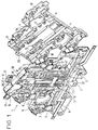
- Figure 1 shows a perspective view of an example of a module connection, terminal block type, single control according to the invention, the housing of which is made up of two articulated adjoining parts one on the other and here shown in the open position before reconciliation.
- Figure 2 shows a front view of one of the two module parts connection according to figure 1.
- Figure 3 shows a perspective view of an example of single control disconnect device for connection module according to Figures 1 and 2 and connecting bars for wire connection terminals with which this device cooperates.
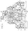
- Figure 4 shows a front view of an alternative embodiment of a module dual control connection according to the invention, the housing is identical to that shown in figure 1.
- Figure 5 shows a perspective view in partial section of an example of a dual control disconnector device for a connection according to figure 4.
- connection module 1 for electrical conductors shown in Figure 1 is for example of the terminal block type, as assumed here. he has a box 2, flat and thin, made of a material insulator and here produced in two parts 2A and 2B simultaneously obtained by molding so as to be laterally articulated one on the other and to form two half-shells which come together by folding one over the other to delimit a volume whose walls are arranged to allow it to house various fixed and / or more or less mobile electrical components.
- the connection module 1 is here supposed to be designed to be able to be associated with a plurality of identical or similar modules grouped on the same support, not shown, which is conventionally a rail of standardized shape in the case of a terminal block type connection module.
- connection module is then likely to include a foot attachment, such as foot 3, of known type with three elements, shown in FIG. 1.
- This fixing foot is positioned at a part of the housing which serves as based.
- Compatible modules and therefore most often identical or similar which can be mounted side by side on the same support generally have two large faces each through which they are likely to join to two other modules coming locate on either side of the module considered when they are mounted alignment on the same support.
- connection module 1 makes part each of one of the two different parts 2A, 2B of the housing of this module and are formed by the front of the wall whose back carries most of the molded relief elements produced essentially in extra thickness for holding and / or guiding the components housed in the case of the connection module 1, such as the pads 4 and cavities for pads 4 ' and the guide 5 or holding elements 5 ′ visible on the part 2B in figure 1.
- connection module includes connection terminals for electrical conductors, these terminals which are possibly susceptible to be spring or stripped holding piece, are assumed to be of the type screw terminal in the exemplary embodiment proposed in FIG. 1.
- each terminal of screw connection is assumed to include a metal cage 6 capable of slide in a housing produced in at least one of the two parts 2A, 2B of the connection module housing and a screw 7 capable of being screwed in the cage 6 and to move the latter relative to one end of a fixed longitudinal and metallic electrical connection bar 8 or 8 'which enters the cage and on which the end of the screw located rests opposite the head of this screw.
- the screwing of the screw 7 causes the support of this screw on the connecting bar 8 or 8 'fixed by reliefs suitable on the back of at least one of the two parts 2A, 2B of the housing and displacement of the cage relative to this terminal strip, from that the screw is in support. This continues until the contact with the bar of the internal wall of the cage which is opposite to that where the screw or possibly until a conductor such as a wire or rod, inserted between this internal wall and this bar.
- the screws 7 are provided maneuverable from outside the module, their operating heads being accessible through individual conduits 9 leading to the outside of the case preferably opposite the latter relative to its base so as to facilitate the operation of the screws.
- Insert holes 10 for electrical conductors are provided in the side walls of the housing at each terminal in the wall formed at this level by one and / or the other of the two parts 2A, 2B of the case to allow and facilitate the setting in place of an electrical conductor before effective connection by tightening screw 7 in a terminal, these orifices being delimited by wall elements of the part or parts 2A, 2B which form a guide funnel, as can be seen in Figures 1 and 2.
- connection module has an at least approximately symmetrical appearance 5 with respect to a median transverse plane symbolized by a trace XX on the Figures 1 and 2.
- the connection terminals have their insertion holes 10 here assumed to be symmetrically distributed on the two opposite side walls of the housing of the connection module which are included on the one hand between the two large faces and on the other hand between the base and the housing wall opposite to this base. These terminals are shown here distributed over two floors with respect to at the base of the case.
- Each terminal is associated with a link strip 8 or 8 'individual, here called terminal electrical link strip which is by example obtained by cutting and whose section is for example of appearance less approximately rectangular.
- Each terminal link bar is here immobilized in the case as indicated above and elongates towards the central part of this case where it ends with an extension 11 serving contact element which is obtained by transverse folding.
- This extension is indeed folded so as to extend parallel to a plane transverse of the housing which in the proposed embodiment is a plane of symmetry, median, this plane being here intended to be perpendicular to the support when the housing is fixed on this support, here assumed to be of the straight rail type.
- the individual connecting bars 8 or 8 ′ of the terminals of interconnectable connection on command of a module are arranged in the housing so that the extensions 11 serving as a contact element of these bars are arranged two by two at the same level and with a same orientation at least per level.
- the two bars of link 8 are located at a first level close to the base. They have their respective extensions 11 parallel and symmetrically arranged on either side on the other side of a plane which is preferably the median transverse plane of the module connection 1 which is here defined by its trace XX.
- the free ends of these extensions are more distant from the base than the folds which are located at their other respective ends.
- the extensions of the two 8 'connecting bars located on a second level, further from the base than the first level, which are also parallel and symmetrical have their ends free closer to the base than the folds they have opposite.
- the extensions serving as contact elements for the terminal electrical connection bars of a module are aligned by levels and level to level in the box that contains them and they have the same orientation at least level by level where they end up at least two to of them.
- connection of two connecting bars 8 or 8 'having their respective extensions 11 situated at the same level and with the same orientation is effected by means of a movable conductive part 12, preferably a flat metal part, comprising at least one comb with two parallel contact lyres 13, each lyre being composed so known per se of two parallel branches whose free ends are formed so as to come elastically around one of the extensions she comes to ride.
- each lyre of symmetrical appearance and at less approximately plane is positioned in a longitudinal plane preferably median or quasi-median of at least the extension 11 and at better from the bar carrying this extension.
- each lyre is connects to the extension with which it comes into contact by straddling it transversely and axially, as seen in particular in FIG. 1. This allows him in particular not to have to bear any forces due to the screwing or unscrewing of the terminal screw which are applied to the bar to which it is connected, if it serves a connection terminal of screw type, as assumed in the figures.
- the movable conductive part 12 is produced by cutting from a flat blank and presents two combs to each two parallel contact lyres 13 in a initial shape, these two combs mounted head to tail can either be maintained assembled as shown in Figure 1, or still be dissociated so that consist of two identical movable conductive half-pieces for a use which will be developed later.
- the movable conductive part 12 with two combs mounted head to tail, symmetrical, which is mentioned above, is fixed at a positioning arrangement 14 by suitable means for example by riveting, by snap-fastening and / or other on an operating part 15 which is movable mounted in the case of the connection module and which is intended for be operated from outside of said housing.
- the operating part 15 is made of insulating material and it has a part forming a rod sliding which is housed between fixed guide elements 5 carried by the back of at least one of the parts 2A, 2B, when these parts are joined and form a closed box.
- the rod that comprises the operating part 15 is provided with a grip 16 which is intended to remain protruding out of the housing whatever the position reached by sliding by the movable conductive part 12 that carries this operating part 15.
- the free ends of the extensions 11 which are located in pairs either at the first level or at the second level in a box are separated by a distance which is greater than the length of the movable conductive part 12.
- This comprises two combs whose lyres are symmetrically arranged with respect to a median transverse plane.
- These combs are mounted head to tail so that the lyres carried by one of the combs is straddled on the extensions bars of the same level with the free ends facing them, so that the lyres of the other comb of this same piece are separated from free ends of the extensions of the bars of the other level by a electrically sufficient distance to avoid connection establishment electric via the air gap separating them as long as the electric voltage maximum admissible is not exceeded.
- the sliding displacement of the movable conductive part 12 by one level at the other, that is to say from a first position to a second allows alternatively to establish an electrical connection either between extensions 11 of bars of the first level, i.e. between extensions 11 of the bars of the second level and therefore between the connection terminals mounted on these bars.
- the operating part 15 comprises a part forming a rod sliding with the end located opposite the gripping head 16 carries the positioning arrangement 14 of movable conductive part 12, this last, for example, snapped in by a central part between the edges a slot-type housing made for it at this end.
- the rod for example has a rectangular cross section and it is guided between guide elements 5 which define a sliding groove and which are carried by the back of at least one of the parts 2A, 2B, when these parts are joined and form a closed case, as already indicated.
- the guidance is carried out by means of a part of the sliding rod which is located near the gripping head 16.
- the end where the positioning arrangement 14 is located is connected to this part by a portion where the stem is thinned so as to leave room for an elastic retention element here constituted by two elastic tabs of positioning 18 which are provided on either side of the rod which they are issued and which rub against the guide elements 5, during sliding of this rod.
- the retention element is intended to cooperate with an additional element of the housing which is here produced in the form of a hollow 19 formed in the guide elements which delimit the guide groove.
- the gripping head 16 is asymmetrical with so that the label holders 20 which it includes are inclined so as to be easily readable, when the module is in place on the support who wears it as part of an installation.
- a gripping tab 21 is laterally formed so as to project from the other side of the gripping head 16 relative to the sliding rod and in a direction opposite to that defined by this rod.
- This paw is here crossed by an opening allowing the passage of a tool rod, such as example a screwdriver rod, intended to be used to move the part of operation 15 and the movable conductive part 12 sliding between the positions provided for them in the connection module.
- the gripping head 16 is also traversed right through by a conduit 22 provided for receiving a connecting rod between the heads of gripping of identical or similar connection modules mounted joined and aligned on the same support, so as to allow simultaneous control of these heads and therefore of the movable conductive parts 12 modules that include them.
- a sliding rod positioning locking device comprising here a part composed of a targette element 23 and a lug of maneuver 24 carried by an elastic tab 25 which is articulated in a groove in at least one holding element 5 'on the back of one and / or the other of parts 2A, 2B.
- connection module variant with two connection pieces and two controls for electrical conductors shown in Figures 4 and 5 is supposed to have a case identical to case 2 mentioned above, well that this is not imperative.
- the conductive parts 12 ′ and 12 " are for example obtained by a middle section of a conductive part 12 leading to separation of the two combs which it comprises, each comb thus separated constituting a conductive parts 12 ', 12 ".
- connection 12 'and 12 "have their lyres oriented in the same direction, the part connection 12 'being intended to cooperate with the extensions 11 of strips 8 located in the connection module like strips 8 a module presented in figure 1.
- connection pieces 12 'and 12 are each fixed at a positioning arrangement carried by a 15 'or 15 "operating part different, this fixation is likely to be done in a way corresponding to that used to fix the connecting piece 12 on the operating part 15.
- the operating parts 15 'and 15 each have a sliding rod one end of which carries a 16 'or 16 "gripping head intended to remain protruding out of the module housing whatever the movements of the operating parts in this case.
- the rods of the two operating parts 15 'and 15 here have different lengths, as can be clearly seen on the Figure 5 and they are arranged so that the connecting pieces 12 'and 12 "are placed in alignment with each other in the housing without ever to be able to touch.
- connection piece is designed to move straight by one position where it straddles the projections 11 of the 8 "strips at a position closer to the wall of the housing which is opposite the base of this housing for which this 12 "connection piece is no longer in contact with these extensions.
- connecting piece 12 ' is provided to move from a position where it straddles the extensions 11 of strips 8 'at a position further from the base of the housing for which it is no longer in contact with these extensions.
- the displacements of the pieces of 12 'and 12 "connection are made straight by sliding the pieces operating 15 'and 15 "on the one hand one on the other and on the other hand one and the other between the guide elements 5 and 5 "which delimit elements of sliding groove for one and / or the other of the rod elements sliding that these two operating parts comprise.
- these guide elements are carried by the back of at least one of the two parts of the housing, when these parts are joined and form a housing closed.
- the operating part 15 ′ is guided in its part closest to the base of the housing by the 5 "guide elements located on either side of the extreme part of this part which carries the part 12 'connection and against which this end part slides.
- the piece of 15 "operation which is the shortest is grooved along its length until level where his 16 "gripping head is located so as to partially receive the sliding rod that comprises the operating part 15 'and at allow the sliding of this rod independently of its own sliding, if necessary.
- the gripping heads 16 'and 16 are here laterally offset, on the one hand, one with respect to the other and, secondly, with respect to the rods of the pieces of maneuver that includes them.
- These heads are made up in a way similar to that provided for the gripping head 16 mentioned above, with notably 24 'and 24 "operating lugs. They include in particular each a portion of conduit 22 via which it is possible to join the two operating parts 15 'and 15 "in positioning a common axis of appropriate diameter simultaneously in the conduit 22 of each of the two parts so that it is possible to possibly move simultaneously with the operating parts identical or similar of aligned and joined connection modules. In the absence of a common axis of this kind, the two operating parts allow to independently move each of the connecting pieces.
Landscapes
- Connections Arranged To Contact A Plurality Of Conductors (AREA)
- Instructional Devices (AREA)
- Switch Cases, Indication, And Locking (AREA)
Abstract
Description
Claims (9)
- Module de raccordement, notamment bloc de jonction, comportant un boítier (2) en matériau isolant qui contient des bornes de connexion, pour des conducteurs électriques parvenant jusqu'aux bornes dans le boítier par l'intermédiaire d'orifices d'insertion (10) ménagés dans des parois de ce boítier, des barrettes (8, 8', 8") de liaison électrique individuelle pour les bornes, ces barrettes étant fixes et s'étendant vers une partie centrale du boítier ou elle se terminent chacune par un prolongement (11) servant d'élément de contact, les prolongements de deux barrettes situés à un même niveau dans le boítier étant susceptibles d'être mis en liaison par l'intermédiaire d'une pièce conductrice (12, 12' ou 12") qui est portée une pièce de manoeuvre manoeuvrable depuis l'extérieur du boítier, lorsque cette pièce de manoeuvre est déplacée par coulissement à l'intérieur du boítier jusqu'à une position où les prolongements des deux barrettes de même niveau préalablement considérés sont individuellement enfourchés chacun par une des lyres que comporte la pièce conductrice, ledit module étant caractérisé en ce qu'il comporte des prolongements de barrette pliés pour se développer parallèlement à un même plan transversal médian du boítier, avec une même orientation des prolongements situés à un même niveau pour permettre à ceux-ci de coopérer avec des lyres d'une pièce conductrice qui viennent chacune enfourcher transversalement et axialement un prolongement dans un plan longitudinal médian de ce prolongement, ainsi qu'au moins une pièce conductrice plane à lyres parallèles disposées en peigne.
- Module de raccordement, selon la revendication 1, caractérisé en ce qu'il comporte un dispositif de verrouillage en position d'une partie formant tige de coulissement de la pièce de manoeuvre (15) , ledit dispositif comportant un élément formant targette (23) dans le boítier et une patte de manoeuvre externe (24) qui sont portés par une patte élastique (25) venant s'articuler dans une rainure (5') du boítier pour permettre à la targette d'élastiquement s'engager dans au moins un cran (26) ménagé au long de la tige de coulissement, en l'absence de traction exercée sur la patte de manoeuvre.
- Module de raccordement, selon l'une des revendications 1, 2, caractérisé en ce qu'il comporte une pièce conductrice (12) comportant des lyres (13), disposées de manière à former deux peignes montés tête-bêche, et des prolongements (11) servant d'éléments de contact d'un premier niveau dont l'orientation est à l'opposé de ceux d'un second niveau de manière qu'au moins deux prolongements du premier niveau soient enfourchés par les lyres d'un de ces peignes pour une première position atteinte par déplacement de la pièce de manoeuvre (15) et qu'au moins deux prolongements du second niveau soient enfourchés par les lyres de l'autre peigne pour une seconde position atteinte par déplacement de la pièce de manoeuvre en sens inverse du précédent.
- Module de raccordement, selon la revendication 1, caractérisé en ce qu'il comporte au moins deux pièces conductrices (12', 12") ayant chacune au moins un peigne muni de lyres de contact (13) parallèles permettant d'enfourcher des prolongements (11) servant d'éléments de contact ayant tous une même orientation par niveau, ainsi qu'un même niveau pour au moins deux prolongements enfourchés par les lyres d'un même peigne, chaque pièce conductrice étant portée par une pièce de manoeuvre (15', 15") différente, ces deux pièces de manoeuvre coulissant d'une part l'une sur l'autre, d'autre part l'une éventuellement avec l'autre entre des éléments de guidage (5, 5") communs intérieurement comportés par le boítier.
- Module de raccordement, selon la revendication 4, caractérisé en ce qu'il comporte des prolongements servant d'éléments de contact situés sur des niveaux différents qui sont alignés de niveau à niveau et des pièces conductrices qui sont alignées entre elles et qui portent des peignes identiquement orientés.
- Module de raccordement, selon l'une des revendications 4,5, caractérisé en ce qu'il comporte des pièces conductrices (12', 12") qui sont respectivement portées par des pièces de manoeuvre (15', 15") mobiles en translation dont l'une à une d'une partie formant tige de coulissement plus courte que celle de l'autre de manière à permettre aux pièces conductrices de se déplacer en translation l'une dans l'alignement de l'autre.
- Module de raccordement, selon l'une des revendications 1 à 6, caractérisé en ce qu'il comporte des prolongements servant d'éléments de contact de même niveau disposés symétriquement par rapport au plan parallèlement auquel ils se développent et au moins une pièce conductrice ayant des lyres de contact de peigne(s) symétriquement disposées par rapport à ce plan qui est portée par une pièce de manoeuvre mobile en translation.
- Module de raccordement, selon l'une des revendications 1 à 7, caractérisé en ce qu'il comporte au moins une pièce de manoeuvre mobile dont les extrémités comportent respectivement une tête de préhension (16, 16', 16") qui reste en saillie hors du boítier quel que soit le déplacement de la pièce de manoeuvre dont elle fait partie et au moins un agencement de positionnement (14) de pièce conductrice, chaque pièce conductrice se déplaçant dans le boítier du module avec la partie de la pièce de manoeuvre où elle est positionnée, au moins une pièce de manoeuvre comportant une partie formant tige de coulissement qui est guidée entre des éléments de guidage intérieurement comportés par le boítier, et qui est munie d'au moins un élément de rétention élastique (18) apte à coopérer avec au moins un élément complémentaire (19) du boítier pour maintenir élastiquement cette pièce de manoeuvre en au moins une position déterminée jusqu'à application d'une force de déplacement suffisante prédéterminée de la pièce de manoeuvre par l'intermédiaire de la tête de préhension que comporte cette pièce de manoeuvre.
- Module de raccordement, selon l'une des revendications 1 à 8, caractérisé en ce qu'il comporte au moins une pièce de manoeuvre mobile (15, 15' 15") dotée d'au moins un agencement de positionnement de pièce conductrice situé à une de ses extrémités, chaque pièce conductrice (12, 12', 12") se déplaçant dans le boítier du module avec la partie de la pièce de manoeuvre où elle est positionnée, chaque pièce de manoeuvre comportant une partie formant tige de coulissement qui est guidée entre des éléments de guidage intérieurement comportés par le boítier, l'autre extrémité de chaque pièce de manoeuvre comportant une tête de préhension (16, 16', 16") qui reste en saillie hors du boítier quel que soit le déplacement de la pièce de manoeuvre dont elle fait partie et qui comporte un conduit transversal (22) pour une tige de solidarisation entre têtes de manoeuvre du même module et/ou de modules identiques ou similaires alignés.
Applications Claiming Priority (2)
| Application Number | Priority Date | Filing Date | Title |
|---|---|---|---|
| FR9615414A FR2757316B1 (fr) | 1996-12-16 | 1996-12-16 | Module de raccordement a bornes de connexion interconnectables par piece(s) conductrice(s) mobile(s) |
| FR9615414 | 1996-12-16 |
Publications (2)
| Publication Number | Publication Date |
|---|---|
| EP0848452A1 true EP0848452A1 (fr) | 1998-06-17 |
| EP0848452B1 EP0848452B1 (fr) | 2002-01-09 |
Family
ID=9498695
Family Applications (1)
| Application Number | Title | Priority Date | Filing Date |
|---|---|---|---|
| EP97402989A Expired - Lifetime EP0848452B1 (fr) | 1996-12-16 | 1997-12-10 | Module de raccordement à bornes de connexion interconnectables par pièce(s) conductrice(s) mobile(s) |
Country Status (5)
| Country | Link |
|---|---|
| US (1) | US6019643A (fr) |
| EP (1) | EP0848452B1 (fr) |
| DE (1) | DE69709533T2 (fr) |
| ES (1) | ES2170351T3 (fr) |
| FR (1) | FR2757316B1 (fr) |
Cited By (2)
| Publication number | Priority date | Publication date | Assignee | Title |
|---|---|---|---|---|
| EP3190664A1 (fr) * | 2016-01-08 | 2017-07-12 | ABB Schweiz AG | Borne de connexion pour appareil électrique équipée d'une cage de serrage en matériau amagnétique |
| EP3244489A1 (fr) * | 2016-05-12 | 2017-11-15 | ABB Schweiz AG | Porte-repère apte à être fixé dans un puits de shunt d'un bloc de jonction |
Families Citing this family (7)
| Publication number | Priority date | Publication date | Assignee | Title |
|---|---|---|---|---|
| DE19964156B4 (de) * | 1999-01-25 | 2004-07-15 | Weidmüller Interface Gmbh & Co. | Elektrisches Gerät |
| DE202006017882U1 (de) * | 2006-11-22 | 2007-03-01 | Cedes Ag | Steckmodul |
| DE202010005557U1 (de) * | 2010-06-04 | 2011-10-31 | Weidmüller Interface GmbH & Co. KG | Rangierklemme in Etagenbauform |
| ES2562465T3 (es) | 2010-06-02 | 2016-03-04 | Weidmüller Interface GmbH & Co. KG | Terminal de puente de forma constructiva en plantas |
| DE102010052871B4 (de) * | 2010-12-01 | 2014-06-05 | Phoenix Contact Gmbh & Co. Kg | Reihenklemme |
| DE102015121057A1 (de) * | 2015-12-03 | 2017-06-08 | Phoenix Contact Gmbh & Co. Kg | Elektrische Klemme |
| JP6992621B2 (ja) * | 2018-03-14 | 2022-01-13 | オムロン株式会社 | 接続子およびソケット |
Citations (4)
| Publication number | Priority date | Publication date | Assignee | Title |
|---|---|---|---|---|
| DE1924454U (de) * | 1965-05-26 | 1965-09-30 | Siemens Ag | Reihenklemme mit steckverbindungsglied. |
| DE2601849A1 (de) * | 1976-01-20 | 1977-07-21 | Wieland Elektrische Industrie | Reihentrennklemme |
| FR2357080A1 (fr) * | 1976-07-02 | 1978-01-27 | Alsthom Cgee | Bloc de jonction |
| EP0386277A1 (fr) * | 1989-03-04 | 1990-09-12 | Weidmüller Interface GmbH & Co. | Borne séparatrice double |
Family Cites Families (4)
| Publication number | Priority date | Publication date | Assignee | Title |
|---|---|---|---|---|
| GB1197146A (en) * | 1968-05-13 | 1970-07-01 | Isaburo Takeyasu | Plate bending Jig |
| FR2483692A1 (fr) * | 1980-05-28 | 1981-12-04 | Alsthom Cgee | Bloc de jonction a sectionneur |
| DE29502186U1 (de) * | 1995-02-10 | 1995-03-30 | Weidmüller Interface GmbH & Co, 32760 Detmold | Elektrische Verteileranordnung |
| FR2743448B1 (fr) * | 1996-01-10 | 1998-02-13 | Entrelec Sa | Agencement d'interconnexion pour appareillage electrique, notamment pour appareillage de type bloc de jonction, et boitier equipe d'un tel agencement |
-
1996
- 1996-12-16 FR FR9615414A patent/FR2757316B1/fr not_active Expired - Fee Related
-
1997
- 1997-12-10 DE DE69709533T patent/DE69709533T2/de not_active Expired - Lifetime
- 1997-12-10 EP EP97402989A patent/EP0848452B1/fr not_active Expired - Lifetime
- 1997-12-10 ES ES97402989T patent/ES2170351T3/es not_active Expired - Lifetime
- 1997-12-15 US US08/990,640 patent/US6019643A/en not_active Expired - Fee Related
Patent Citations (4)
| Publication number | Priority date | Publication date | Assignee | Title |
|---|---|---|---|---|
| DE1924454U (de) * | 1965-05-26 | 1965-09-30 | Siemens Ag | Reihenklemme mit steckverbindungsglied. |
| DE2601849A1 (de) * | 1976-01-20 | 1977-07-21 | Wieland Elektrische Industrie | Reihentrennklemme |
| FR2357080A1 (fr) * | 1976-07-02 | 1978-01-27 | Alsthom Cgee | Bloc de jonction |
| EP0386277A1 (fr) * | 1989-03-04 | 1990-09-12 | Weidmüller Interface GmbH & Co. | Borne séparatrice double |
Cited By (3)
| Publication number | Priority date | Publication date | Assignee | Title |
|---|---|---|---|---|
| EP3190664A1 (fr) * | 2016-01-08 | 2017-07-12 | ABB Schweiz AG | Borne de connexion pour appareil électrique équipée d'une cage de serrage en matériau amagnétique |
| FR3046702A1 (fr) * | 2016-01-08 | 2017-07-14 | Abb Technology Ag | Borne de connexion pour appareil electrique equipee d'une cage de serrage en materiau amagnetique |
| EP3244489A1 (fr) * | 2016-05-12 | 2017-11-15 | ABB Schweiz AG | Porte-repère apte à être fixé dans un puits de shunt d'un bloc de jonction |
Also Published As
| Publication number | Publication date |
|---|---|
| FR2757316A1 (fr) | 1998-06-19 |
| EP0848452B1 (fr) | 2002-01-09 |
| US6019643A (en) | 2000-02-01 |
| FR2757316B1 (fr) | 1999-01-22 |
| DE69709533T2 (de) | 2002-09-19 |
| ES2170351T3 (es) | 2002-08-01 |
| DE69709533D1 (de) | 2002-02-14 |
Similar Documents
| Publication | Publication Date | Title |
|---|---|---|
| EP0735629B1 (fr) | Agencement de connexion pour fils conducteurs électriques et module, notamment de type bloc de jonction, équipé d'un tel agencement | |
| EP0511111B1 (fr) | Connexion électrique et boîtier d'appareil électrique comportant une telle connexion | |
| EP0878032B1 (fr) | Connecteur de derivation pour cable souterrain | |
| EP0848452B1 (fr) | Module de raccordement à bornes de connexion interconnectables par pièce(s) conductrice(s) mobile(s) | |
| EP0470887A1 (fr) | Connecteur de dérivation | |
| EP0208233B1 (fr) | Agencement de connexion auto-dénudant encastré pour appareillage électrique et outil de connexion pour un tel agencement | |
| EP0005087A1 (fr) | Système d'accessoires de raccordement pour rail d'alimentation électrique à profil asymétrique | |
| EP3333871B1 (fr) | Appareil électrique de coupure d'un courant électrique | |
| EP0723314B1 (fr) | Connecteur électrique | |
| EP0555157B1 (fr) | Dispositif de raccordement d'un disjonteur basse tension à boîtier moulé | |
| FR2531577A1 (fr) | Contact electrique a pression a pouvoir de fermeture et d'ouverture incorpore | |
| EP0097599B1 (fr) | Dispositif électromagnétique tel que transformateur électrique, du genre comportant une carcasse en deux parties | |
| EP0080389B1 (fr) | Contact électrique et application à un connecteur | |
| EP1026782B1 (fr) | Bloc d'interconnexion pour appareils électriques | |
| EP0134742B1 (fr) | Dispositif de connexion pour faisceau de fils électriques, et procédé de réalisation | |
| FR2766628A1 (fr) | Peigne d'interconnexion pour alignement de bornes de raccordement electrique d'un appareillage et module(s) de logement d'appareillage correspondant(s) | |
| FR2647977A3 (fr) | Ensemble guide-cable flexible avec insertion transversale des cables | |
| EP0478469B1 (fr) | Bornier de raccordement pour la distribution du neutre et de la terre dans un coffret électrique | |
| EP0768727A1 (fr) | Bornier électrique | |
| FR2541049A1 (fr) | Dispositif de connexion autodenudant | |
| CH668501A5 (fr) | Contacteur inverseur en particulier pour commander un moteur electrique a deux sens de marche. | |
| FR2489609A1 (fr) | Module de raccordement de conducteurs electriques a connecteurs amovibles | |
| FR2476393A1 (fr) | Connecteur a force d'insertion nulle, notamment pour circuit integre | |
| FR2661046A1 (fr) | Dispositif d'interconnexion permettant de raccorder deux cables electriques non denudes. | |
| EP1916744A1 (fr) | Dispositif de pontage à deux niveaux de raccordement permettant la connexion de becs de repiquage |
Legal Events
| Date | Code | Title | Description |
|---|---|---|---|
| PUAI | Public reference made under article 153(3) epc to a published international application that has entered the european phase |
Free format text: ORIGINAL CODE: 0009012 |
|
| AK | Designated contracting states |
Kind code of ref document: A1 Designated state(s): AT BE CH DE DK |
|
| AX | Request for extension of the european patent |
Free format text: AL;LT;LV;MK;RO;SI |
|
| AKX | Designation fees paid |
Free format text: DE ES FR GB IT |
|
| RBV | Designated contracting states (corrected) |
Designated state(s): DE ES FR GB IT |
|
| 17P | Request for examination filed |
Effective date: 19981207 |
|
| R17P | Request for examination filed (corrected) |
Effective date: 19981227 |
|
| 17Q | First examination report despatched |
Effective date: 20000222 |
|
| GRAG | Despatch of communication of intention to grant |
Free format text: ORIGINAL CODE: EPIDOS AGRA |
|
| GRAG | Despatch of communication of intention to grant |
Free format text: ORIGINAL CODE: EPIDOS AGRA |
|
| GRAH | Despatch of communication of intention to grant a patent |
Free format text: ORIGINAL CODE: EPIDOS IGRA |
|
| GRAH | Despatch of communication of intention to grant a patent |
Free format text: ORIGINAL CODE: EPIDOS IGRA |
|
| GRAA | (expected) grant |
Free format text: ORIGINAL CODE: 0009210 |
|
| REG | Reference to a national code |
Ref country code: GB Ref legal event code: IF02 |
|
| AK | Designated contracting states |
Kind code of ref document: B1 Designated state(s): DE ES FR GB IT |
|
| REF | Corresponds to: |
Ref document number: 69709533 Country of ref document: DE Date of ref document: 20020214 |
|
| GBT | Gb: translation of ep patent filed (gb section 77(6)(a)/1977) |
Effective date: 20020405 |
|
| REG | Reference to a national code |
Ref country code: ES Ref legal event code: FG2A Ref document number: 2170351 Country of ref document: ES Kind code of ref document: T3 |
|
| PLBE | No opposition filed within time limit |
Free format text: ORIGINAL CODE: 0009261 |
|
| STAA | Information on the status of an ep patent application or granted ep patent |
Free format text: STATUS: NO OPPOSITION FILED WITHIN TIME LIMIT |
|
| 26N | No opposition filed | ||
| PGFP | Annual fee paid to national office [announced via postgrant information from national office to epo] |
Ref country code: GB Payment date: 20031203 Year of fee payment: 7 Ref country code: ES Payment date: 20031203 Year of fee payment: 7 |
|
| REG | Reference to a national code |
Ref country code: FR Ref legal event code: CJ Ref country code: FR Ref legal event code: CD Ref country code: FR Ref legal event code: CA |
|
| PG25 | Lapsed in a contracting state [announced via postgrant information from national office to epo] |
Ref country code: GB Free format text: LAPSE BECAUSE OF NON-PAYMENT OF DUE FEES Effective date: 20041210 |
|
| PG25 | Lapsed in a contracting state [announced via postgrant information from national office to epo] |
Ref country code: ES Free format text: LAPSE BECAUSE OF NON-PAYMENT OF DUE FEES Effective date: 20041211 |
|
| GBPC | Gb: european patent ceased through non-payment of renewal fee |
Effective date: 20041210 |
|
| PG25 | Lapsed in a contracting state [announced via postgrant information from national office to epo] |
Ref country code: IT Free format text: LAPSE BECAUSE OF NON-PAYMENT OF DUE FEES;WARNING: LAPSES OF ITALIAN PATENTS WITH EFFECTIVE DATE BEFORE 2007 MAY HAVE OCCURRED AT ANY TIME BEFORE 2007. THE CORRECT EFFECTIVE DATE MAY BE DIFFERENT FROM THE ONE RECORDED. Effective date: 20051210 |
|
| REG | Reference to a national code |
Ref country code: ES Ref legal event code: FD2A Effective date: 20041211 |
|
| PGFP | Annual fee paid to national office [announced via postgrant information from national office to epo] |
Ref country code: DE Payment date: 20121220 Year of fee payment: 16 |
|
| REG | Reference to a national code |
Ref country code: DE Ref legal event code: R119 Ref document number: 69709533 Country of ref document: DE |
|
| REG | Reference to a national code |
Ref country code: DE Ref legal event code: R119 Ref document number: 69709533 Country of ref document: DE Effective date: 20140701 |
|
| PG25 | Lapsed in a contracting state [announced via postgrant information from national office to epo] |
Ref country code: DE Free format text: LAPSE BECAUSE OF NON-PAYMENT OF DUE FEES Effective date: 20140701 |
|
| REG | Reference to a national code |
Ref country code: FR Ref legal event code: PLFP Year of fee payment: 19 |
|
| REG | Reference to a national code |
Ref country code: FR Ref legal event code: PLFP Year of fee payment: 20 |
|
| PGFP | Annual fee paid to national office [announced via postgrant information from national office to epo] |
Ref country code: FR Payment date: 20161222 Year of fee payment: 20 |