EP0848457A2 - Elektrische Anschlussvorrichtung - Google Patents
Elektrische Anschlussvorrichtung Download PDFInfo
- Publication number
- EP0848457A2 EP0848457A2 EP97121337A EP97121337A EP0848457A2 EP 0848457 A2 EP0848457 A2 EP 0848457A2 EP 97121337 A EP97121337 A EP 97121337A EP 97121337 A EP97121337 A EP 97121337A EP 0848457 A2 EP0848457 A2 EP 0848457A2
- Authority
- EP
- European Patent Office
- Prior art keywords
- housing
- connection device
- electrical
- electrical connection
- lever arm
- Prior art date
- Legal status (The legal status is an assumption and is not a legal conclusion. Google has not performed a legal analysis and makes no representation as to the accuracy of the status listed.)
- Withdrawn
Links
- 238000003780 insertion Methods 0.000 claims abstract description 37
- 230000037431 insertion Effects 0.000 claims abstract description 37
- 239000004020 conductor Substances 0.000 abstract description 6
- 238000001125 extrusion Methods 0.000 abstract 2
- 238000009413 insulation Methods 0.000 description 3
- 241001295925 Gegenes Species 0.000 description 1
- 238000001514 detection method Methods 0.000 description 1
- 230000003993 interaction Effects 0.000 description 1
Images


Classifications
-
- H—ELECTRICITY
- H01—ELECTRIC ELEMENTS
- H01R—ELECTRICALLY-CONDUCTIVE CONNECTIONS; STRUCTURAL ASSOCIATIONS OF A PLURALITY OF MUTUALLY-INSULATED ELECTRICAL CONNECTING ELEMENTS; COUPLING DEVICES; CURRENT COLLECTORS
- H01R4/00—Electrically-conductive connections between two or more conductive members in direct contact, i.e. touching one another; Means for effecting or maintaining such contact; Electrically-conductive connections having two or more spaced connecting locations for conductors and using contact members penetrating insulation
- H01R4/24—Connections using contact members penetrating or cutting insulation or cable strands
- H01R4/2416—Connections using contact members penetrating or cutting insulation or cable strands the contact members having insulation-cutting edges, e.g. of tuning fork type
- H01R4/242—Connections using contact members penetrating or cutting insulation or cable strands the contact members having insulation-cutting edges, e.g. of tuning fork type the contact members being plates having a single slot
- H01R4/2425—Flat plates, e.g. multi-layered flat plates
- H01R4/2429—Flat plates, e.g. multi-layered flat plates mounted in an insulating base
- H01R4/2433—Flat plates, e.g. multi-layered flat plates mounted in an insulating base one part of the base being movable to push the cable into the slot
-
- H—ELECTRICITY
- H01—ELECTRIC ELEMENTS
- H01R—ELECTRICALLY-CONDUCTIVE CONNECTIONS; STRUCTURAL ASSOCIATIONS OF A PLURALITY OF MUTUALLY-INSULATED ELECTRICAL CONNECTING ELEMENTS; COUPLING DEVICES; CURRENT COLLECTORS
- H01R4/00—Electrically-conductive connections between two or more conductive members in direct contact, i.e. touching one another; Means for effecting or maintaining such contact; Electrically-conductive connections having two or more spaced connecting locations for conductors and using contact members penetrating insulation
- H01R4/24—Connections using contact members penetrating or cutting insulation or cable strands
- H01R4/2404—Connections using contact members penetrating or cutting insulation or cable strands the contact members having teeth, prongs, pins or needles penetrating the insulation
- H01R4/2412—Connections using contact members penetrating or cutting insulation or cable strands the contact members having teeth, prongs, pins or needles penetrating the insulation actuated by insulated cams or wedges
Definitions
- the present invention relates to an electrical connection device with a housing in which at least one contact element can be placed.
- the object of the present invention is in specifying an electrical connection device with which an electrical line is safe and at a defined Position can be contacted with the contact element.
- the electrical Line is insertable with respect to the contact element to be positioned so that reliable and defined contacting is feasible. That also arranged in the housing rotatable lever element, which with its short lever arm into the Housing engages and that on its long lever arm from outside the housing is actuated, allows the Safe and defined contacting of the electrical line with the contact element with relatively little effort can be effected by actuating the long lever arm the short lever arm the guide element against the contact element presses, the contact element in the contacting recess engages and thus one in the insertion hole of the Guide element introduced electrical line contacted.
- the short lever arm of the lever element is designed as an eccentric the long lever arm increases exerted on the guide element with the short lever arm Force is essentially linear. This is due to the The fact that depending on the effective section, i.e. depending on sector of the eccentric bearing against the guide element, due to due to the changing radius of the eccentric the effective length of the short lever arm the aspect ratio of the two lever arms changes. With a trained as an eccentric short lever arm of the lever element is a particularly energy-saving pressing on the guide element the contact element possible. It is also through the eccentric the long lever at its base, so near the pivot point the lever element reinforced, so that the risk of Breaking off the long lever arm is reduced.
- the contact element has at least one cutting element and the cutting element when pressing the long one Lever arm pressing the guide element against the contact element engages in the contacting recess, is a safe and defined contacting of electrical Lines leading into the insertion hole of the guide element are introduced, also for electrical cables Insulation in the connection or contact area not beforehand was removed, possible.
- the cutting element separates the insulation of the electrical in a manner known per se Line and thereby makes electrical contact at the same time conductive the otherwise enclosed by the insulation Management.
- two contact elements can be placed and in the housing two guide elements are insertable, it is advantageously possible two electrical lines that can each be inserted into one of the two guide elements, by means of the electrical connection device e.g. with a electrical device. If the two contact elements inside the electrical connection device e.g. are electrically connected, it is easier in this way Possible, e.g. supplied to a first electrical device electrical potential in the same way to one to supply further electrical device by using the first contact element contacted the electrical line Potential is introduced to the first electrical device and by contacting with the second contact element electrical line the same potential to another electrical device is introduced.
- connection device on opposite inner sides of the housing arranged, it is advantageously e.g. possible, Conductor tracks of a circuit board that are in the area in which the electrical connection device to the circuit board is introduced as a direct connector is to contact on each side of the circuit board.
- the two contact elements are either depending on the application electrically isolated from each other or electrically contacted with each other.
- the electrical connection device When the electrical connection device according to the invention at least one of the side surfaces of the housing is a positive locking element or has a positive connection, it is advantageously possible, the electrical connection device mechanically detachable with its housing e.g. with a a corresponding positive connection or a corresponding Form-locking element having electrical device to which potentials by means of the connecting device according to the invention or signals are introduced to releasably connect.
- the electrical connection device according to the invention is above can be cascaded in addition or alternatively, if at least one of the side surfaces of the housing is a Has positive locking element and if the at least one Side surface opposite side surface a corresponding Has positive locking. It is then advantageous possible several of the electrical according to the invention Connectors to an electrical connector block assemble and thus related electrical Lines with their respective connection device easy to handle.
- the connecting device according to the invention in the rear area the insertion hole is at least partially less than in Area of the insertion opening, it is advantageously possible in the guide element electrical lines with different Introduce cross section while doing this electrical Contact lines at a defined position.
- the contact element e.g. a first cutting element for a large one Cross section and a second cutting element for a smaller one Has cross section.
- a contact of the electrical wire with a large cross section with the cutting element for the small cross-section would also damage the conductor of the electrical line itself, while trying to use an electrical conductor small cross section with a cutting element for a large one Cross-section contact, often not a satisfactory one electrical contacting is achievable.
- the cross section of the insertion hole of the guide element at least in parts in the rear area of the insertion hole is less than in the area of the insertion opening in this rear area of the insertion hole only electrical Lines with a correspondingly small cross-section introduce. Electrical cables that are due to their Cross section in this section of the insertion hole is not more are introduced by a contact element in the contacted the front area of the insertion hole; Cables, which also insert into the rear area of the insertion hole leave, at least in the rear area of the insertion hole contacted by the corresponding contact element.
- the connection device AV has a housing GA in which the two contact elements KES are placed (examples with others Number of contact elements KES and corresponding corresponding according to other mechanical and electrical elements the following description are also conceivable.).
- the two guide elements are also in the housing GA FE introduced.
- the guide elements FE have an insertion hole with an insertion opening FEE.
- In the insertion hole of the guide elements FE are electrical lines EL ', EL' 'introduced, being in the first guide element FE an electrical line with a large cross section EL 'and in the second guide element FE has an electrical line small cross section EL '' is introduced.
- a rotatable Lever element HE with an eccentric in the exemplary embodiment HEK trained short lever arm HEK and a long lever arm HEL arranged.
- the short lever arm HEK it works Lever element HE in the housing GA of the electrical connection device AV on, with the lever element HE on the long lever arm HEL can be actuated from outside the housing GA.
- the lever element HE a pin HEZ on, in a corresponding hole in the housing GA engages and acts as the axis of rotation of the lever element HE.
- FIG 2 shows the electrical connection device according to the invention AV from the back, i.e. from the side from which the electrical lines EL ', EL' 'in the insertion hole of the Guide elements FE are introduced.
- Figures 1 and 2 show the lever elements HE in a position in which the guide elements FE in the housing GA of the electrical connection device AV can be inserted or removed from it.
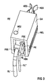
- FIG. 3 shows the electrical connection device AV with actuated Lever elements HE, i.e. the long lever arms HEL der Lever elements HE are up to the provided recesses of the housing GA moves, the short lever arm HEK in in 3 not shown, the guide element FE against the contact element KES presses, making an electrically conductive Contact between the electrical lines EL ', EL' 'and the respective contact element KES is effected.
- actuated Lever elements HE i.e. the long lever arms HEL der Lever elements HE are up to the provided recesses of the housing GA moves, the short lever arm HEK in in 3 not shown, the guide element FE against the contact element KES presses, making an electrically conductive Contact between the electrical lines EL ', EL' 'and the respective contact element KES is effected.
- connection device AV a cuboid, convex outer contour, which is particularly a series similar connection devices allowed.
- the electrical connection device AV according to the invention to at least one of the side surfaces of the housing GA one in FIG. 3 not shown positive locking and at least on one opposite this first side surface of the housing GA second side surface a corresponding positive locking element on. So that the electrical connection device AV cascadable so that functionally or electrically belong together electrical lines EL ', EL' 'together, i.e. in one Block of similar electrical connection devices are manageable.
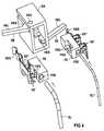
- connection device AV in a partial exploded view showing the detection the interaction of the mechanical components of the connection device AV inside the housing GA relieved.
- the housing GA has a slot-shaped recess, in which the lever element HE can be inserted.
- the lever element HE is in this recess and thus at least partially inside of the housing GA arranged, whereby for easy placement of the lever element HE either the housing GA in several parts can be formed, or the axis of rotation of the lever element HE acting pins HEZ subsequently by the corresponding one Recess in the housing GA in the lever element HE can be introduced.
- the eccentric HEK of the lever element HE engages in a recess FEA of the guide element FE.
- the FE guide element can only be inserted into the GA housing if the long lever arm HEL of the lever element HE pivoted out of the housing GA is, as shown in FIG 1. Because then it's ins Effective radius of the eccentric HEK inside the housing low.
- the guide element FE can thus in the housing GA be introduced, as shown in FIG 2.
- the guide element FE can therefore face in one direction of insertion translational movement from the housing GA the electrical connection device can no longer be moved.
- the long lever arm HEL of the lever element HE continues in Direction towards the housing GA thus towards the slit-shaped Recess of the housing GA pivoted, so presses effective radius of the eccentric HEK that increases Guide element FE against that also arranged in the housing GA Contact element KES, which in the embodiment cutting elements SE ', SE' 'arranged on the contact element KES in contact recesses FEK of the guide element FE intervention.
- the contact element KES has two Cutting elements SE ', SE' 'on one of an insulating Sheathed electrical line EL ', EL' 'in itself contact in a known manner. Stripping the electrical Lines EL ', EL' 'are therefore not required in this case.
- the guide element FE through corresponding contact recesses FEK shape that one in the area of the insertion hole of the Guide element FE inserted and stripped electrical Line EL ', EL' 'with a correspondingly designed Contact element KES is contacted.
- the cutting elements SE ', SE '' of the contact element KES therefore expressly only an exemplary embodiment, with the help of Cutting elements SE ', SE' 'a safe and particularly fast Contacting of the electrical line EL ', EL' 'guaranteed is because the time-consuming stripping of the electrical Lines EL ', EL' ', usually with a corresponding one Tool executed, not required.
- the electrical connection device AV according to FIGS. 1 to 4 has two contact elements KES, which on the opposite Inside of the housing GA are arranged. Also on opposite inner sides of the housing arranged lever elements HE is one of the Guide elements FE against one of the contact elements KES pressable.
- the contact element KES is in the front Area designed as a spring element and contacts e.g. a Trace of an electrical circuit board that is in the area in which the connecting device to the circuit board is introduced as a direct connector is.
- Connection device AV a conductor track on one Side of the circuit board with the electrical line EL 'and using a trace on the other side of the circuit board the electrical line EL '' electrically connected will.
- the front parts of the contact element KES can however just as e.g. shaped as a pin or a socket be.
- the guide element FE is limited by a corresponding geometric Design of the insertion hole the insertion depth the electrical line EL ', EL' '. This is the cross section the insertion hole in the rear area of the insertion hole at least piecewise less than in the area of the insertion opening FAIRY.
- An electrical line with a small cross-section EL '' is therefore deeper into the insertion hole of the guide element FE insertable as an electrical cable with a large cross-section EL '.
- In the rear area of the insertion hole in only the electrical line EL '' with a small cross-section is insertable, reach through the corresponding contact recesses FEK only the cutting elements SE '' a.
- the cutting elements SE '' differ from the Cutting elements SE 'in that they have an electrical line contact with a small cross section EL '' while the Cutting elements SE 'an electrical line with a larger Contact cross section EL '.
Landscapes
- Details Of Connecting Devices For Male And Female Coupling (AREA)
Abstract
Description
- wobei das Führungselement eine Einführbohrung mit einer Einführöffnung aufweist, in die eine elektrische Leitung einführbar ist und wobei das Führungselement mindestens eine Kontaktierungsausnehmung aufweist,
- wobei im Gehäuse ein drehbares Hebelelement angeordnet ist, wobei dieses mit seinem kurzem Hebelarm in das Gehäuse eingreift und an seinem langen Hebelarm von außerhalb des Gehäuses betätigbar ist und
- wobei mit Betätigen des langen Hebelarmes der kurze Hebelarm das Führungselement gegen das Kontaktelement preßt, wobei das Kontaktelement in die Kontaktierungsausnehmung eingreift.
- FIG 1 und FIG 2
- eine elektrische Anschlußvorrichtung aus verschiedenen Blickrichtungen,
- FIG 3
- eine elektrische Anschlußvorrichtung mit betätigten Hebelelementen und
- FIG 4
- eine elektrische Anschlußvorrichtung in einer Teil-Explosionsdarstellung.
Claims (8)
- Elektrische Anschlußvorrichtung mit einem Gehäuse (GA) in dem mindestens ein Kontaktelement (KES) plazierbar ist und in das zumindest ein Führungselement (FE) einführbar ist,wobei das Führungselement (FE) eine Einführbohrung mit einer Einführöffnung (FEE) aufweist, in die eine elektrische Leitung (EL', EL'') einführbar ist und wobei das Führungselement (FE) mindestens eine Kontaktierungsausnehmung (FEK) aufweist,wobei im Gehäuse (GA) ein drehbares Hebelelement (HE) angeordnet ist, wobei dieses mit seinem kurzen Hebelarm (HEK) in das Gehäuse (GA) eingreift und an seinem langen Hebelarm (HEL) von außerhalb des Gehäuses (GA) betätigbar ist undwobei mit Betätigen des langen Hebelarms (HEL) der kurze Hebelarm (HEK) das Führungselement (FE) gegen das Kontaktelement (KES) preßt, wobei das Kontaktelement (KES) in die Kontaktierungsausnehmung (FEK) eingreift.
- Elektrische Anschlußvorrichtung nach Anspruch 1, dadurch gekennzeichnet, daß der kurze Hebelarm (HEK) des Hebelelementes (HE) als Exzenter (HEK) ausgebildet ist.
- Elektrische Anschlußvorrichtung nach Anspruch 1 oder 2, dadurch gekennzeichnet, daß das Kontaktelement (KES) mindestens ein Schneidelement (SE', SE'') aufweist und daß das Schneidelement (SE', SE'') in die Kontaktierungsausnehmung (FEK) eingreift.
- Elektrische Anschlußvorrichtung nach Anspruch 1, 2 oder 3, dadurch gekennzeichnet, daß im Gehäuse (GA) zwei Kontaktelemente (KES) plazierbar sind und daß in das Gehäuse (GA) zwei Führungselemente (FE) einführbar sind.
- Elektrische Anschlußvorrichtung nach Anspruch 4, dadurch gekennzeichnet, daß die zwei Kontaktelemente (KES) an gegenüberliegenden Innenseiten des Gehäuses (GA) plazierbar sind.
- Elektrische Anschlußvorrichtung nach einem der obigen Ansprüche, dadurch gekennzeichnet, daß zumindest eine der Seitenflächen des Gehäuses (GA) ein Formschlußelement oder eine Formschlußaufnahme aufweist.
- Elektrische Anschlußvorrichtung nach einem der obigen Ansprüche, dadurch gekennzeichnet, daß zumindest eine der Seitenflächen des Gehäuses (GA) ein Formschlußelement aufweist, und daß die der zumindest einen Seitenfläche gegenüberliegende Seitenfläche eine Formschlußaufnahme aufweist.
- Elektrische Anschlußvorrichtung nach einem der obigen Ansprüche, dadurch gekennzeichnet, daß der Querschnitt der Einführbohrung im hinteren Bereich der Einführbohrung zumindest stückweise geringer ist, als im Bereich der Einführöffnung (FEE).
Applications Claiming Priority (2)
| Application Number | Priority Date | Filing Date | Title |
|---|---|---|---|
| DE19651958 | 1996-12-13 | ||
| DE19651958 | 1996-12-13 |
Publications (2)
| Publication Number | Publication Date |
|---|---|
| EP0848457A2 true EP0848457A2 (de) | 1998-06-17 |
| EP0848457A3 EP0848457A3 (de) | 1999-05-06 |
Family
ID=7814653
Family Applications (1)
| Application Number | Title | Priority Date | Filing Date |
|---|---|---|---|
| EP97121337A Withdrawn EP0848457A3 (de) | 1996-12-13 | 1997-12-04 | Elektrische Anschlussvorrichtung |
Country Status (1)
| Country | Link |
|---|---|
| EP (1) | EP0848457A3 (de) |
Cited By (2)
| Publication number | Priority date | Publication date | Assignee | Title |
|---|---|---|---|---|
| GB2364185A (en) * | 2000-06-27 | 2002-01-16 | Technetix Plc | Holder for electrical connectors and enclosure having a crimping tool |
| EP1289066A3 (de) * | 2001-06-30 | 2004-01-02 | Weidmüller Interface GmbH & Co. | Reihenklemme und Führungshülse |
Family Cites Families (4)
| Publication number | Priority date | Publication date | Assignee | Title |
|---|---|---|---|---|
| US2627537A (en) * | 1949-08-06 | 1953-02-03 | Allied Electric Products Inc | Attachment plug |
| DE2449326A1 (de) * | 1974-10-14 | 1976-04-22 | Siemens Ag | Klemmanschlussvorrichtung zur kontaktierung zwischen einem elektrischen leiter und einem anschlusselement |
| US4701138A (en) * | 1986-12-18 | 1987-10-20 | Phoenix Terminal Blocks Inc. | Solderless electrical connector |
| AU678743B2 (en) * | 1995-03-31 | 1997-06-05 | Matsushita Electric Works Ltd. | Lever modular jack electrical connector |
-
1997
- 1997-12-04 EP EP97121337A patent/EP0848457A3/de not_active Withdrawn
Cited By (3)
| Publication number | Priority date | Publication date | Assignee | Title |
|---|---|---|---|---|
| GB2364185A (en) * | 2000-06-27 | 2002-01-16 | Technetix Plc | Holder for electrical connectors and enclosure having a crimping tool |
| GB2364185B (en) * | 2000-06-27 | 2004-06-30 | Technetix Plc | Enclosures for housing electrical connectors |
| EP1289066A3 (de) * | 2001-06-30 | 2004-01-02 | Weidmüller Interface GmbH & Co. | Reihenklemme und Führungshülse |
Also Published As
| Publication number | Publication date |
|---|---|
| EP0848457A3 (de) | 1999-05-06 |
Similar Documents
| Publication | Publication Date | Title |
|---|---|---|
| DE3239708C2 (de) | ||
| DE60014719T2 (de) | Kabelverbinder mit gesteuerter impedanz | |
| DE69123238T2 (de) | Hochdichte- und mehrfacheinfügungsverbinder | |
| DE3318135C2 (de) | ||
| DE60300371T2 (de) | Stecker | |
| DE2443476C2 (de) | Elektrisches Verbindungsstück | |
| DE69517347T2 (de) | Elektrischer Verbinder | |
| DE19835459C2 (de) | Anschlußklemme für elektrische Leiter | |
| DE10045498A1 (de) | Elektrische Reihenklemme | |
| DE60002281T2 (de) | Flexibler Verbinder mit integrierter Übertragungsleitung | |
| DE2745655B2 (de) | Koaxialstecker | |
| DE69416079T2 (de) | Klemmverbinder | |
| EP1586137A1 (de) | Kabelsteckverbinder | |
| EP2107648A1 (de) | Steckverbinder mit einer Schirmauflage | |
| EP1594193B1 (de) | Kontaktvorrichtung | |
| DE19511508A1 (de) | Elektrischer Verbinder | |
| EP3782238A1 (de) | Geschirmtes steckverbindermodul für einen modularen industriesteckverbinder | |
| DE3201142C2 (de) | ||
| DE69934855T2 (de) | Elektrischer Verbinder | |
| DE4102541C1 (de) | ||
| WO2021004893A1 (de) | Direktsteckverbinder | |
| EP0557781A2 (de) | Verbindungsanordnung zwischen einem Koax-Kabel und den Messern einer Rückwand-Verdrahtungsplatte | |
| DE60033088T2 (de) | Spannungsführender Steckanschluss | |
| DE102022113144A1 (de) | Steckverbinder mit einer rasteinrichtung zur verriegelung einer steckverbindung mit einem gegensteckverbinder, gegensteckverbinder sowie anordnung mit einem steckverbinder und einem gegensteckverbinder | |
| DE2413445C2 (de) | Elektrischer Zwittersteckverbinder |
Legal Events
| Date | Code | Title | Description |
|---|---|---|---|
| PUAI | Public reference made under article 153(3) epc to a published international application that has entered the european phase |
Free format text: ORIGINAL CODE: 0009012 |
|
| AK | Designated contracting states |
Kind code of ref document: A2 Designated state(s): AT CH DE ES FR GB LI |
|
| AX | Request for extension of the european patent |
Free format text: AL;LT;LV;MK;RO;SI |
|
| PUAL | Search report despatched |
Free format text: ORIGINAL CODE: 0009013 |
|
| AK | Designated contracting states |
Kind code of ref document: A3 Designated state(s): AT BE CH DE DK ES FI FR GB GR IE IT LI LU MC NL PT SE |
|
| AX | Request for extension of the european patent |
Free format text: AL;LT;LV;MK;RO;SI |
|
| 17P | Request for examination filed |
Effective date: 19990607 |
|
| AKX | Designation fees paid |
Free format text: AT CH DE ES FR GB LI |
|
| 17Q | First examination report despatched |
Effective date: 20000202 |
|
| STAA | Information on the status of an ep patent application or granted ep patent |
Free format text: STATUS: THE APPLICATION IS DEEMED TO BE WITHDRAWN |
|
| 18D | Application deemed to be withdrawn |
Effective date: 20000815 |