EP0848511A2 - Einrichtung zum Ein- und Auskoppeln optischer Signale zweier Übertragungskanäle - Google Patents
Einrichtung zum Ein- und Auskoppeln optischer Signale zweier Übertragungskanäle Download PDFInfo
- Publication number
- EP0848511A2 EP0848511A2 EP97114145A EP97114145A EP0848511A2 EP 0848511 A2 EP0848511 A2 EP 0848511A2 EP 97114145 A EP97114145 A EP 97114145A EP 97114145 A EP97114145 A EP 97114145A EP 0848511 A2 EP0848511 A2 EP 0848511A2
- Authority
- EP
- European Patent Office
- Prior art keywords
- amplifier
- signals
- coupler
- transmission channels
- optical
- Prior art date
- Legal status (The legal status is an assumption and is not a legal conclusion. Google has not performed a legal analysis and makes no representation as to the accuracy of the status listed.)
- Withdrawn
Links
- 230000005540 biological transmission Effects 0.000 title claims abstract description 50
- 230000003287 optical effect Effects 0.000 title claims abstract description 30
- 230000008878 coupling Effects 0.000 title claims abstract description 10
- 238000010168 coupling process Methods 0.000 title claims abstract description 10
- 238000005859 coupling reaction Methods 0.000 title claims abstract description 10
- 239000013307 optical fiber Substances 0.000 claims description 9
- 230000000903 blocking effect Effects 0.000 claims description 3
- 239000000835 fiber Substances 0.000 claims description 2
- 230000003321 amplification Effects 0.000 description 1
- 230000001419 dependent effect Effects 0.000 description 1
- 238000011161 development Methods 0.000 description 1
- 230000018109 developmental process Effects 0.000 description 1
- 230000004927 fusion Effects 0.000 description 1
- 238000012986 modification Methods 0.000 description 1
- 230000004048 modification Effects 0.000 description 1
- 238000003199 nucleic acid amplification method Methods 0.000 description 1
- 230000008054 signal transmission Effects 0.000 description 1
Images
Classifications
-
- H—ELECTRICITY
- H04—ELECTRIC COMMUNICATION TECHNIQUE
- H04B—TRANSMISSION
- H04B10/00—Transmission systems employing electromagnetic waves other than radio-waves, e.g. infrared, visible or ultraviolet light, or employing corpuscular radiation, e.g. quantum communication
- H04B10/29—Repeaters
- H04B10/291—Repeaters in which processing or amplification is carried out without conversion of the main signal from optical form
- H04B10/293—Signal power control
- H04B10/2933—Signal power control considering the whole optical path
- H04B10/2939—Network aspects
-
- H—ELECTRICITY
- H04—ELECTRIC COMMUNICATION TECHNIQUE
- H04B—TRANSMISSION
- H04B10/00—Transmission systems employing electromagnetic waves other than radio-waves, e.g. infrared, visible or ultraviolet light, or employing corpuscular radiation, e.g. quantum communication
- H04B10/29—Repeaters
- H04B10/291—Repeaters in which processing or amplification is carried out without conversion of the main signal from optical form
- H04B10/298—Two-way repeaters, i.e. repeaters amplifying separate upward and downward lines
Definitions
- EP 0 440 276 B1 describes an optical fiber transmission link for telecommunications signals, with an optical amplifier, in which service signals are coupled in and out in front of and behind the amplifier via a coupler, which have a different wavelength than the telecommunications signals .
- the telecommunications signals, but not the service signals, are routed through the amplifier.
- the intermediate Filter has blocking effect from the first Couplers decoupled signals.
- the subject of the application with the features of claim 1 has the following advantage:
- the device enables both the amplification of several transmission channels by the same optical amplifier and the coupling and decoupling of transmission channels using only one optical amplifier in each transmission direction in a simple manner.
- the signals of the coupled-in transmission channel occupy a wavelength range (frequency range) that is not occupied by the decoupled transmission channel or by the remaining transmission channels for which the amplifier is intended.
- the necessary selection can depend on the input or Coupling out separately.
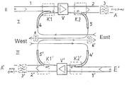
- the figure shows a schematic representation of a preferred one Embodiment of the invention.
- an input E and an output A a device with an optical transmission path for signals of the telecommunication.
- an optical coupler K1 preferably a fiber fusion coupler, which is an optical amplifier V connects.
- Its output is an optical coupler K2 downstream, which leads to an optical fiber 2.
- This optical waveguide 2 is not mandatory to be provided blocking filter 3 with the output A of the device connected.
- the coupler K1 has a feed 4, to which optical Signals are coming from the East direction.
- the optical one Coupler K2 has a branch 5, from the optical Signals go west. In this direction an optical bandpass filter 6 is provided (not mandatory), this (especially if the coupler K2 with respect to its branch 5 is not frequency-selective) tunable can be.
- the description of the exemplary embodiment has hitherto been related the invention on a device called I that for a particular direction of transmission of signals of at least one channel n from input E to Output A is provided.
- a basically the same facility II is below the Device I shown to reverse the transfer Direction.
- the reference number of the facility II correspond to those of facility I, are but each with an apostrophe.
- optical fiber 1 Because of the same function of facilities I and II only the function of the device I described.
- Through the optical amplifier are therefore the signals of at least the transmission channels to reinforce n and o.
- Through the following optical Couplers K2 are the signals via branch 5 a transmission channel m branched, which is one of the n transmission channels that is input E forth are supplied via the optical fiber 1. From the branch 5 pass the signals (through the bandpass filter 6 limited to the bandwidth of the transmission channel m) to the west. Leave the signals of the remaining channels the coupler K2 over the optical fiber 2.
- the notch filter 3 ensures that the signals of the transmission channel m are filtered out, so that ultimately only signals of the transmission channels at output A stay n (without m) and o.
- the number of the transmission channels via the amplifier are larger than the number of transmission channels at the input and / or exit of the facility, but only then to one Limitation of the number of transferable transmission channels leads when the amplifier bandwidth is the limit for the number of channels. It is more important that through the invention the number of optical amplifiers required and thus the costs are reduced.
- Block filter 3 Even if the coupler K2 is so little wavelength selective is that on the optical fiber 2 also signals of Transmission channel m, it may be useful that Block filter 3 to omit when the signals of the transmission channel m should be distributed in several directions, namely towards the west and in the direction behind the exit A.
- the bandpass filter 6 is tunable, one can Channel selection takes place, provided the coupler K2 procures this way is that through the branch 5 signals of several transmission channels flow.
- n, o, m not only for one transmission channel, but can also stand for several transmission channels.
Landscapes
- Physics & Mathematics (AREA)
- Electromagnetism (AREA)
- Engineering & Computer Science (AREA)
- Computer Networks & Wireless Communication (AREA)
- Signal Processing (AREA)
- Optical Communication System (AREA)
Abstract
Die Einrichtung ist als Add/Drop-Multiplexer geeignet und ermöglicht auf einfache Weise das Ein- und Auskoppeln von Übertragungskanälen unter Verwendung nur eines optischen Verstärkers je Übertragungsrichtung.
Description
In der EP 0 440 276 B1 ist eine optische Lichtwellenleiter-Übertragungsstrecke für Telecommunikationssignale, mit einem optischen Verstärker beschrieben, bei der in Verstärkernähe vor und hinter dem Verstärker jeweils über einen Koppler Servicesignale ein- und ausgekoppelt werden, die eine andere Wellenlänge aufweisen wie die Telecommunikationssignale. Dabei werden zwar die Telecommunikationssignale, nicht aber die Servicesignale über den Verstärker geführt.
Die Einrichtung ermöglicht auf einfache Weise sowohl die Verstärkung mehrerer Übertragungskanäle durch denselben optischen Verstärker als auch das Ein- und Auskoppeln von Übertragungskanälen unter Verwendung nur eines optischen Verstärkers je Übertragungsrichtung. Dabei belegen die Signale des eingekoppelten Übertragungskanals einen Wellenlängenbereich (Frequenzbereich), der weder vom ausgekoppelten Übertragungskanal noch von den restlichen Übertragungskanälen belegt ist, für die der Verstärker vorgesehen ist.
Claims (13)
- Einen optischen Verstärker (V) enthaltende Einrichtung zum Ein- und Auskoppeln von optischen Signalen, die in Übertragungsrichtung gesehen vor und hinter dem Verstärker (V) je einen optischen Koppler (K1, K2) aufweist,
dadurch gekennzeichnet,daß der Verstärker (V) für mindestens zwei Übertragungskanäle (o, n) unterschiedlicher Wellenlängenbereiche vorgesehen ist,daß der vor dem Verstärker (V) angeordnete Koppler (K1) zum Einkoppeln von über den Verstärker (V) zu führenden Signalen eines ersten der Übertragungskanäle (o) vorgesehen ist unddaß der hinter demselben Verstärker (V) angeordnete Koppler (K2) zum Auskoppeln von über den Verstärker (V) geführten Signalen eines zweiten der Übertragungskanäle (m) vorgesehen ist. - Einen optischen Verstärker (V) enthaltende Einrichtung zum Ein- und Auskoppeln von optischen Signalen, die einerseits zwischen ihrem Eingang (E) und dem Verstärker (V) einen ersten optischen Koppler (K1) und andererseits zwischen dem Verstärker (V) und ihrem Ausgang (A) einen zweiten optischen Koppler (K2) aufweist, dadurch gekennzeichnet,daß der Verstärker (V) für mindestens zwei Übertragungskanäle (n, o) unterschiedlicher Wellenlängenbereiche vorgesehen ist,daß der erste Koppler (K1) zum Einkoppeln von über den Verstärker (V) zu führenden Signalen eines ersten der Übertragungskanäle (o) vorgesehen ist,daß der zweite Koppler (K2) zum Auskoppeln von über den Verstärker (V) geführten Signalen eines zweiten der Übertragungskanäle (m) vorgesehen ist unddaß die Anzahl der über den Verstärker (V) geführten Übertragungskanäle (n, o) größer ist als die Anzahl der Übertragungskanäle am Eingang (E) und/oder Ausgang (A) der Einrichtung.
- Einrichtung nach Anspruch 1 oder 2, dadurch gekennzeichnet, daß sie Teil eines Add/Drop-Multiplexers ist.
- Einrichtung nach einem der vorangehenden Ansprüche, dadurch gekennzeichnet, daß wenigstens einer der Koppler (K1, K2) ein Faserkoppler ist.
- Einrichtung nach einem der vorangehenden Ansprüche, dadurch gekennzeichnet, daß wenigstens einer der Koppler (K1, K2) wellenlängenselektiv ist.
- Einrichtung nach einem der vorangehenden Ansprüche, dadurch gekennzeichnet, daß dem Abzweig (5) des auskoppelnden Kopplers (K2) ein wellenlängenselektives Bandpaßfilter (6) für die ausgekoppelten Signale nachgeschaltet ist.
- Einrichtung nach Anspruch 6 und einem der Ansprüche 1 bis 4, dadurch gekennzeichnet, daß das Bandpaßfilter (6)abstimmbar ist.
- Einrichtung nach einem der vorangehenden Ansprüche, dadurch gekennzeichnet, daß hinter dem auskoppelnden Koppler (K2) im Übertragungsweg für die nicht ausgekoppelten Signale ein Sperrfilter (3) mit Sperrungwirkung für den Übertragungskanal (m) der ausgekoppelten Signale vorgesehen ist.
- Einrichtung nach einem der vorangehenden Ansprüche, dadurch gekennzeichnet, daß sie für Übertragungskanäle (n, o, m) vorgesehen ist, deren Wellenlängen im selben Übertragungsfenster eines Lichtwellenleiters liegen.
- Einrichtung nach einem der vorangehenden Ansprüche, dadurch gekennzeichnet, daß sie für ein Kommunikationsnetz vorgesehen ist und die Koppler (K1, K2) am selben Ort angeordnet sind wie der Verstärker (V).
- Einrichtung nach einem der vorangehenden Ansprüche, dadurch gekennzeichnet, daß die Koppler (K1, K2) im selben Gerät angeordnet sind wie der Verstärker (V).
- Einrichtung nach einem der vorangehenden Ansprüche, dadurch gekennzeichnet, daß sie zusammen mit einer gleichen Einrichtung (II) für die entgegengesetzte Übertragungsrichtung im selben Gerät angeordnet ist.
- Einrichtung nach einem der vorangehenden Ansprüche, dadurch gekennzeichnet, daß der Verstärker (V) für mehr als zwei Übertragungskanäle (o, n) unterschiedlicher Wellenlängenbereiche vorgesehen ist.
Applications Claiming Priority (2)
| Application Number | Priority Date | Filing Date | Title |
|---|---|---|---|
| DE19651236 | 1996-12-10 | ||
| DE19651236A DE19651236A1 (de) | 1996-12-10 | 1996-12-10 | Einrichtung zum Ein- und Auskoppeln optischer Signale zweier Übertragungskanäle |
Publications (2)
| Publication Number | Publication Date |
|---|---|
| EP0848511A2 true EP0848511A2 (de) | 1998-06-17 |
| EP0848511A3 EP0848511A3 (de) | 2003-10-01 |
Family
ID=7814203
Family Applications (1)
| Application Number | Title | Priority Date | Filing Date |
|---|---|---|---|
| EP97114145A Withdrawn EP0848511A3 (de) | 1996-12-10 | 1997-08-16 | Einrichtung zum Ein- und Auskoppeln optischer Signale zweier Übertragungskanäle |
Country Status (3)
| Country | Link |
|---|---|
| US (1) | US6014481A (de) |
| EP (1) | EP0848511A3 (de) |
| DE (1) | DE19651236A1 (de) |
Families Citing this family (17)
| Publication number | Priority date | Publication date | Assignee | Title |
|---|---|---|---|---|
| US5923848A (en) * | 1996-05-31 | 1999-07-13 | Microsoft Corporation | System and method for resolving names in an electronic messaging environment |
| US5898801A (en) | 1998-01-29 | 1999-04-27 | Lockheed Martin Corporation | Optical transport system |
| JP3483751B2 (ja) * | 1997-12-18 | 2004-01-06 | 三菱電機株式会社 | 動きベクトル検出装置及び動きベクトル検出方法 |
| US6301404B1 (en) * | 1998-03-17 | 2001-10-09 | Nec Corporation | Supervisory signal optical bypass circuit, optical amplifying repeater and supervisory system |
| US6708004B1 (en) * | 1998-12-01 | 2004-03-16 | Tyco Telecommunications (Us) Inc. | Method and apparatus for reducing crosstalk between a monitoring channel and a data channel in a WDM optical communication system |
| DE19917751C2 (de) * | 1999-04-20 | 2001-05-31 | Nokia Networks Oy | Verfahren und Überwachungsvorrichtung zur Überwachung der Qualität der Datenübertragung über analoge Leitungen |
| US20020101874A1 (en) * | 2000-11-21 | 2002-08-01 | Whittaker G. Allan | Physical layer transparent transport information encapsulation methods and systems |
| US7085497B2 (en) | 2002-04-03 | 2006-08-01 | Lockheed Martin Corporation | Vehicular communication system |
| US20040076434A1 (en) * | 2002-09-27 | 2004-04-22 | Whittaker G. Allan | Optical distribution network for RF and other analog signals |
| US6912339B2 (en) * | 2002-09-27 | 2005-06-28 | Lockheed Martin Corporation | Optical interface devices having balanced amplification |
| US7283480B1 (en) | 2002-11-12 | 2007-10-16 | Lockheed Martin Corporation | Network system health monitoring using cantor set signals |
| US7349629B1 (en) | 2002-11-26 | 2008-03-25 | Lockheed Martin Corporation | Methods and systems for creating a digital interconnect fabric |
| US7424228B1 (en) | 2003-03-31 | 2008-09-09 | Lockheed Martin Corporation | High dynamic range radio frequency to optical link |
| WO2004093351A2 (en) * | 2003-03-31 | 2004-10-28 | Lockheed Martin Corporation | Optical network interface systems and devices |
| US7440699B1 (en) | 2004-06-28 | 2008-10-21 | Lockheed Martin Corporation | Systems, devices and methods for transmitting and receiving signals on an optical network |
| CN106199836B (zh) * | 2016-07-21 | 2019-01-25 | 浙江大学 | 一种基于硅基波导光栅的带宽可调滤波器 |
| US10649140B1 (en) | 2019-03-04 | 2020-05-12 | Globalfoundries Inc. | Back-end-of-line blocking structures arranged over a waveguide core |
Family Cites Families (7)
| Publication number | Priority date | Publication date | Assignee | Title |
|---|---|---|---|---|
| IT1238032B (it) * | 1990-01-30 | 1993-06-23 | Pirelli Cavi Spa | Linea di telecomunicazione a fibre ottiche con canali separati di servizio |
| DE4007097A1 (de) * | 1990-03-07 | 1991-09-19 | Daimler Benz Ag | Optisches kommunikationssystem |
| US5132976A (en) * | 1991-05-28 | 1992-07-21 | At&T Bell Laboratories | Electrically tunable fiber ring laser |
| US5181210A (en) * | 1991-05-28 | 1993-01-19 | At&T Bell Laboratories | Electrically tunable fiber ring laser |
| US5225922A (en) * | 1991-11-21 | 1993-07-06 | At&T Bell Laboratories | Optical transmission system equalizer |
| JP3272897B2 (ja) * | 1995-02-27 | 2002-04-08 | 安藤電気株式会社 | 光パルス発生器 |
| US5812291A (en) * | 1995-03-22 | 1998-09-22 | Cselt Centro Studi E Laboratori Telecomunicazioni S.P.A. | Optical add-drop multiplexer for optical communication networks |
-
1996
- 1996-12-10 DE DE19651236A patent/DE19651236A1/de not_active Withdrawn
-
1997
- 1997-08-16 EP EP97114145A patent/EP0848511A3/de not_active Withdrawn
- 1997-12-08 US US08/986,707 patent/US6014481A/en not_active Expired - Lifetime
Also Published As
| Publication number | Publication date |
|---|---|
| EP0848511A3 (de) | 2003-10-01 |
| US6014481A (en) | 2000-01-11 |
| DE19651236A1 (de) | 1998-06-18 |
Similar Documents
| Publication | Publication Date | Title |
|---|---|---|
| EP0193190B1 (de) | Optisches Nachrichtenübertragungssystem im Teilnehmeranschlussbereich | |
| EP0848511A2 (de) | Einrichtung zum Ein- und Auskoppeln optischer Signale zweier Übertragungskanäle | |
| DE3231296C2 (de) | ||
| DE2400491C2 (de) | Fasernetz für die optoelektronische Übertragung von Daten | |
| DE3821772B4 (de) | Optische Zweiwege-Signalübertragungsvorrichtung mit einer Einrichtung zur Fehlerlokalisierung | |
| EP0040706B1 (de) | Optisches Kommunikationssystem | |
| EP0458782B1 (de) | Sternförmiges netz für die datenkommunikation zwischen stationen | |
| EP0394728A2 (de) | Optisches Nachrichtenübertragungssystem für den Teilnehmeranschlussbereich | |
| DE69609086T2 (de) | Kompensation der wellenlängendispersionssteigung in optischen übertragungssystemen | |
| EP0164652A2 (de) | Optisches Nachrichtenübertragungssystem im Teilnehmeranschlussbereich | |
| DE68920459T2 (de) | Umschaltungseinrichtung für Übertragungsleitungen. | |
| DE69115390T2 (de) | Optischer Sternkoppler mit der Verwendung von faseroptischer Verstärkungstechnik | |
| DE10039950C2 (de) | Bidirektionaler optischer Verstärker | |
| DE4322129A1 (de) | Verfahren und Vorrichtung zur Überwachung von Netzwerken mit verzweigten optischen Leitungen | |
| DE69322962T2 (de) | Verfahren zur teilnehmerverbindungsherstellung und teilnehmernetzwerk | |
| EP0445364A2 (de) | Optisches Kommunikationssystem | |
| DE3789137T2 (de) | Verfahren zur Erweiterung der Uebertragungskapazität in einem Netzwerkübertragungssystem für optische Teilnehmer. | |
| EP0914012A2 (de) | Vorrichtung zum Zusammenführen und Verstärken von zwei breitbandigen Signalen | |
| DE69029170T2 (de) | Vorrichtung zur Steuerung der Bandbreite in einer Übertragungseinrichtung mittels Monomodenfaser, unabhängig vom Signalformat | |
| DE10048460B4 (de) | Raman-Verstärker | |
| DE69715043T2 (de) | Ein bidirektionaler wegeleiter und ein verfahren zur unidirektionalen verstärkung | |
| DE19727670C1 (de) | Einrichtung zur Verteilung von Breitbandsignalen | |
| EP0549862B1 (de) | Optisches Nachrichtennetz | |
| DE60309105T2 (de) | Verfahren zur Herstellung und Verbesserung einer optischen Übertragungsleitung und Kompensationsmodulen dafür | |
| EP1121777A1 (de) | Optisches unidirektionales ringnetz |
Legal Events
| Date | Code | Title | Description |
|---|---|---|---|
| PUAI | Public reference made under article 153(3) epc to a published international application that has entered the european phase |
Free format text: ORIGINAL CODE: 0009012 |
|
| AK | Designated contracting states |
Kind code of ref document: A2 Designated state(s): AT BE CH DE DK ES FI FR GB GR IE IT LI LU MC NL PT SE |
|
| AX | Request for extension of the european patent |
Free format text: AL;LT;LV;RO;SI |
|
| RAP1 | Party data changed (applicant data changed or rights of an application transferred) |
Owner name: MARCONI COMMUNICATIONS GMBH |
|
| PUAL | Search report despatched |
Free format text: ORIGINAL CODE: 0009013 |
|
| AK | Designated contracting states |
Kind code of ref document: A3 Designated state(s): AT BE CH DE DK ES FI FR GB GR IE IT LI LU MC NL PT SE |
|
| AX | Request for extension of the european patent |
Extension state: AL LT LV RO SI |
|
| AKX | Designation fees paid | ||
| REG | Reference to a national code |
Ref country code: DE Ref legal event code: 8566 |
|
| STAA | Information on the status of an ep patent application or granted ep patent |
Free format text: STATUS: THE APPLICATION IS DEEMED TO BE WITHDRAWN |
|
| 18D | Application deemed to be withdrawn |
Effective date: 20040402 |