EP0848572A1 - Systeme acoustique - Google Patents
Systeme acoustique Download PDFInfo
- Publication number
- EP0848572A1 EP0848572A1 EP96908354A EP96908354A EP0848572A1 EP 0848572 A1 EP0848572 A1 EP 0848572A1 EP 96908354 A EP96908354 A EP 96908354A EP 96908354 A EP96908354 A EP 96908354A EP 0848572 A1 EP0848572 A1 EP 0848572A1
- Authority
- EP
- European Patent Office
- Prior art keywords
- channel
- synthesizing
- sound
- signal
- difference
- Prior art date
- Legal status (The legal status is an assumption and is not a legal conclusion. Google has not performed a legal analysis and makes no representation as to the accuracy of the status listed.)
- Withdrawn
Links
Images
Classifications
-
- H—ELECTRICITY
- H04—ELECTRIC COMMUNICATION TECHNIQUE
- H04R—LOUDSPEAKERS, MICROPHONES, GRAMOPHONE PICK-UPS OR LIKE ACOUSTIC ELECTROMECHANICAL TRANSDUCERS; ELECTRIC HEARING AIDS; PUBLIC ADDRESS SYSTEMS
- H04R5/00—Stereophonic arrangements
- H04R5/027—Spatial or constructional arrangements of microphones, e.g. in dummy heads
-
- H—ELECTRICITY
- H04—ELECTRIC COMMUNICATION TECHNIQUE
- H04R—LOUDSPEAKERS, MICROPHONES, GRAMOPHONE PICK-UPS OR LIKE ACOUSTIC ELECTROMECHANICAL TRANSDUCERS; ELECTRIC HEARING AIDS; PUBLIC ADDRESS SYSTEMS
- H04R2205/00—Details of stereophonic arrangements covered by H04R5/00 but not provided for in any of its subgroups
- H04R2205/022—Plurality of transducers corresponding to a plurality of sound channels in each earpiece of headphones or in a single enclosure
-
- H—ELECTRICITY
- H04—ELECTRIC COMMUNICATION TECHNIQUE
- H04S—STEREOPHONIC SYSTEMS
- H04S2400/00—Details of stereophonic systems covered by H04S but not provided for in its groups
- H04S2400/01—Multi-channel, i.e. more than two input channels, sound reproduction with two speakers wherein the multi-channel information is substantially preserved
-
- H—ELECTRICITY
- H04—ELECTRIC COMMUNICATION TECHNIQUE
- H04S—STEREOPHONIC SYSTEMS
- H04S2400/00—Details of stereophonic systems covered by H04S but not provided for in its groups
- H04S2400/15—Aspects of sound capture and related signal processing for recording or reproduction
-
- H—ELECTRICITY
- H04—ELECTRIC COMMUNICATION TECHNIQUE
- H04S—STEREOPHONIC SYSTEMS
- H04S3/00—Systems employing more than two channels, e.g. quadraphonic
Definitions
- the present invention relates to a microphone unit for collecting sounds which can be reproduced as being substantially real and stereophonic and a sound processing method, a recording medium on which the sound processed through the microphone unit and the sound processing method is recorded and a method for broadcasting those sounds.
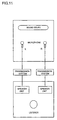
- the sound from the sound source is picked up by a microphone L and a microphone R.
- Each sound collected by the microphone L and the microphone R is transmitted through the respective transmission systems L and R separately.
- the sound is reproduced through a speaker unit L and a speaker unit R corresponding to the respective transmission systems.
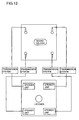
- Fig. 12 is a schematic view representing the quadraphonic mode.
- the sound from the sound source is picked up by 4 channels, i.e., 4 microphones locating at the respective 4 corners of the area around the sound source, a front right microphone F/R, a front left microphone F/L, a rear right microphone R/R and a rear left microphone R/L, respectively.
- 4 channels i.e., 4 microphones locating at the respective 4 corners of the area around the sound source, a front right microphone F/R, a front left microphone F/L, a rear right microphone R/R and a rear left microphone R/L, respectively.
- Each sound recorded by those 4 microphones is separately transmitted through the respective 4 transmission systems to 4 speaker units corresponding to the respective 4 microphones for reproduction.
- the sound field provided from those speaker units can exhibit substantially a real impression.
- quadraphonic mode is assumed to have 4-channel sound collection and 4-channel sound reproduction, stabilization of the sound field has been limited.
- the conventional stereo mode and quadraphonic mode have failed to provide the sound reproduction with full reality.
- a microphone unit comprising:
- the definition of the term "semi-spherical” is not limited to a sphere shape in mathematical aspect but includes the shape which can be virtually recognized as being spherical as well as the one having an almost ellipsoidal shape. It is preferable that the semi-spherical structure has a diameter ranging from 10 to 50 cm. It is also preferable that the semi-spherical structure has a diameter ranging from 10 to 40 cm, more preferably, ranging from 10 to 30 cm or the most preferably, ranging from 15 to 20 cm.
- each distance between the microphone elements becomes too small to provide the reproduced sound with full reality. While if the semi-spherical structure base has an excessively large size, each distance between the microphone elements becomes so large that each microphone element cannot pick up the same sound from the sound source.
- the semi-spherical structure base is formed of a microporous material.
- the semi-spherical structure base may be formed as a solid construction.
- the one formed of a porous ceramics such as a pumice stone or a foaming resin material of a microporous structure provided more stereophonic sound reproduction compared with that of solid structure.
- the semi-spherical structure base is a composite structure formed of a semi-spherical skin layer and a sound absorbing agent filled with the inside of the skin layer.
- the first microphone element and the second microphone element are preferably of the stereo type.
- An arrangement in the semi-spherical structure base for removably accommodating the microphone element allows for easy movement.
- the object of the present invention is realized by a method of reproducing a sound using a microphone unit in which a first microphone element of 2-channel type having at least two directivities is attached to a left end of a semi-spherical structure base and a second microphone element of 2-channel type having at least two directivities is attached to a right end of said semi-spherical structure base, said method comprising steps of:
- the object of the present invention is realized by a method of reproducing a sound using a microphone unit in which a first microphone element of 2-channel type having at least two directivities is attached to a left end of a semi-spherical structure base and a second microphone element of 2-channel type having at least two directivities is attached to a right end of said semi-spherical structure base, said method comprising steps of:
- the frequency correction step corrects each frequency of the second channel signal and the fourth channel signal so that winding occurs in a high frequency when plotting a sound pressure to an axis of ordinate and a frequency to an axis of abscissa.
- One of the most important characteristics of the auditory sense of a human is the ability to recognize the sound which is heard from front of or behind him/her.
- each human ear is generally on the left and right side of the head, the sound heard from front or behind can also be recognized attributable to the concha of the ear which changes the sound tone.
- the sound coming from the front is lead to an auris external through a complex structure of the concha. While the sound behind is heard as being in a high range with a unique winding in the presence of the concha functioning as a screen.
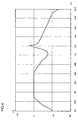
- the frequency correction is executed by rendering the second channel signal and the fourth channel signal to have frequency characteristics exhibiting a big drop of (valley) about 9dB in the range from 500 to 1100 Hz, a sharp peak of about 3dB in the range from 2000 to 3000 Hz and a decline in the range from 4000 Hz to 16000 Hz.
- the frequency correction is not limited to the one shown in Fig. 4.
- the similar correction is available as far as the stereophonic sound reproduction is realized.
- the above-described structure preferably has a diameter ranging from 10 to 50 cm.
- the object of the present invention is realized by a method of processing a collected sound using a microphone unit in which a first microphone element of 2-channel type having at least two directivities is attached to a left end of a semi-spherical structure base and a second microphone element of 2-channel type having at least two directivities is attached to a right end of said semi-spherical structure base, said method comprising:
- This processing method is suitable for reproducing the sound collected through the above microphone unit by means of the reproducing system of stereo type, i.e., two speaker units.
- a delay time is set in the range from 0.5 msec. to 1.0 msec. and the delay step produces two difference signals having delay times of 0.5 msec. and 1.0 msec., respectively. It is further preferable that the delay step produces two difference signals having delay times of 0.5 msec. and 1.0 msec., respectively.
- the third synthesizing step synthesizes a difference signal produced in the first difference signal generation step, a plurality of difference signals produced in the first delay step and a signal produced in the first synthesizing step so that a volume level of a total of the difference signal produced in the first difference signal generation step and a plurality of difference signals produced in the first delay step is not larger than that of the signal produced in the first synthesizing step
- the fourth synthesizing step also synthesizes a difference signal produced in the second difference signal generation step, a plurality of difference signals produced in the second delay step and a signal produced in the second synthesizing step so that a volume level of a total of the difference signal produced in the second difference signal generation step and the plurality of difference signals produced in the second delay step is not larger than that of the signal produced in the second synthesizing step.
- the third synthesizing step synthesizes so that a volume level ratio of a total of the difference signal produced in the first difference signal generation step and a plurality of difference signals produced in the first delay step becomes 0.3 to 0.8 to the signal produced in the first synthesizing step as a value 1.
- the fourth synthesizing step further synthesizes so that a volume level ratio of a total of the difference signal produced in the second difference signal generation step and a plurality of difference signals produced in the second delay step becomes 0.3 to 0.8 to the signal produced in the second synthesizing step as a value 1.
- the volume level ratio of the signal generated in the synthesizing step to the total of the difference signal and a plurality of delayed difference signals is 1 : 0.6.
- the above-processed sound can be recorded on the recording medium, which is easily reproduced as full stereophonic sound through the reproducing system of the stereo type.
- the above-processed sounds can also exhibit full stereophonic and real impression.
- the object of the present invention is realized by a channel conversion system for converting sounds collected through 4 channels, a first channel for collecting front left sound, a second channel for collecting rear left sound, a third channel for collecting front right sound and a fourth channel for collecting rear right sound, into 2-channel sounds, said channel conversion system comprising:
- the frequency correction means executes frequency correction so that winding occurs in a high frequency when plotting a sound pressure to an axis of ordinate and a frequency to an axis of abscissa. It is further preferable that the frequency correction means is constructed so that each of the second channel signal and the fourth channel signal has a frequency characteristic exhibiting a big drop of about 9dB in the range from 500 to 1100 Hz, a sharp peak of about 3dB in the range from 2000 to 3000 Hz and a decline in the range from 4000 Hz to 16000 Hz.
- a sound signal processing system for processing sound signals comprising:
- delay times of the first delay means and the second delay means are ranged from 0.5 msec. to 1.0 msec.
- the first synthesizing means synthesizes a difference signal produced in the first difference signal generation means, a plurality of difference signals produced in the first delay means and the first channel signal so that a volume level of a total of the difference signal produced in the first difference signal generation means and a plurality of difference signals produced in the first delay means is not larger than that of the first channel signal
- the second synthesizing means further synthesizes a difference signal produced in the second difference signal generation means, a plurality of difference signals produced in the second delay means and the second channel signal so that a volume level of a total of the difference signal produced in the second difference signal production means and the plurality of difference signals produced in the second delay means is not larger than that of said second channel signal.
- the first synthesizing means synthesizes so that a volume level ratio of a total of the difference signal produced in the first difference signal generation means and a plurality of difference signals produced in the first delay means becomes 0.3 to 0.8 to the first channel signal as a value 1.
- the second synthesizing means further synthesizes so that a volume level ratio of a total of the difference signal produced in the second difference signal generation means and a plurality of difference signals produced in the second delay means becomes 0.3 to 0.8 to the second channel signal as a value 1.
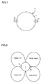
- Fig. 1 is a perspective view showing a microphone unit A of the present invention.
- Fig. 2 is a plan view of the microphone unit A of the present invention.
- a reference numeral 1 is a sphere structure having a diameter of 18 cm.
- the inside of the sphere structure 1 is filled with a urethane foaming resin.
- An FRP is used for covering a whole surface of the urethane foaming resin. That is the sphere structure 1 is formed of the urethane foaming resin and the FRP as a skin layer forming the spherical shape.
- Reference numerals 2a and 2b are stereo type microphone elements. As shown in the drawings, each base section of the microphone elements 2a and 2b is removably embedded in the right and left end of the sphere structure 1. As Fig. 2 shows, the microphone element 2a is designed to pick up sounds coming from front left and rear left. The microphone element 2b is designed to pick up sounds coming from front right and rear right.
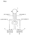
- Fig. 3 is a block diagram of the channel conversion system.
- the one for picking up the front left sound is designated as a first channel F/L and the other for picking up the rear left sound is designated as a second channel R/L.
- the one for picking up the front right sound is designated as a third channel F/R and the other for picking up the rear right sound is designated as a fourth channel R/R.
- a reference numeral 31 is a equalizer.
- the equalizer 31 receives signals of the second channel R/L and the fourth channel R/R, which will be frequency corrected by rendering characteristics shown in Fig. 4 therewith. It is intended to correct the frequency of those signals so as to have a big drop (valley) of approximately 9 dB in the range from 500 to 1100 Hz, an acute peak of approximately 3 dB in the range from 2000 to 3000 Hz, and damping in the range from 4000 Hz to 16000Hz.
- a reference numeral 32 is a first synthesizer for synthesizing a sound of the first channel F/L and a sound of the second channel R/L which has been corrected into 1 channel.
- a reference numeral 33 is a second synthesizer for synthesizing a sound of the third channel F/R and a sound of the fourth channel R/R which has been corrected into 1 channel.
- sounds collected through 4 channels are converted into 2-channels sounds.
- the above channel conversion system is effective particularly for the case of listening the sound through a head phone.
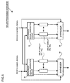
- Fig. 5 is a block diagram of a sound processing system 100.
- a reference numeral 51 is a first difference signal generation circuit where a second channel signal is subtracted from a first channel signal in order to obtain a difference signal, i.e., a matrix signal.
- a reference numeral 52 is a second difference signal generation circuit where the first channel signal is subtracted from the second channel signal in order to obtain a difference signal, i.e., a matrix signal.
- Reference numerals 53 1 to 53 n are first delay circuits. Different delay times ranging from 0.5 msec. to 1.0 msec. are set in the respective delay circuits 53 1 to 53 n for delaying an output signal of the difference signal generation circuit 51 for a preset delay time. Supposing that 0.5 msec. is set in the delay circuit 53 1 as the delay time, the output signal of the difference signal generation circuit 51 is output from the delay circuit 53 1 delayed for 0.5 msec.
- Reference numerals 54 1 to 54 n are second delay circuits. Different delay times ranging from 0.5 msec. to 1.0 msec. are set in the respective delay circuits 54 1 to 54 n for delaying an output signal of the difference signal generation circuit 52 for a preset delay time. Supposing that 0.5 msec. is set in the delay circuit 54 1 as the delay time, the output signal of the difference signal generation circuit 52 is output from the delay circuit 54 1 delayed for 0.5 msec.
- Reference numeral 55 is a first synthesizer for synthesizing a first channel signal, an output signal of the difference signal generation circuit 51 and output signals of the delay circuits 53 1 to 53 n . Supposing that a volume level of the first channel signal is 1, the synthesizer 55 is designed to synthesize those signals so that the total volume level of the output signal of the difference signal generation circuit 51 and those of the delay circuits 53 1 to 53 n becomes 0.3 to 0.8.
- a reference numeral 56 is a second synthesizer for synthesizing a second channel signal, an output signal of the difference signal generation circuit 52 and those of the delay circuits 54 1 to 54 n . Supposing that a volume level of the second channel signal is 1, the synthesizer 56 is designed to synthesize those signals so that the total volume level of the output signal of the difference signal generation circuit 52 and those of the delay circuits 54 1 to 54 n becomes 0.3 to 0.8.
- delay circuits 53 1 , 53 2 , 54 1 and 54 2 are used and 0.5 msec. is set in the delay circuits 53 1 and 54 1 and 1.0 msec. is set in the delay circuits 53 2 and 54 2 as delay times, respectively.
- the synthesizers 55 and 56 are designed to synthesize the output signals of the difference signals generation circuit and the delay circuit so that the total volume level ratio becomes 0.6.
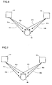
- Fig. 6 and Fig. 7 are schematic views showing how the system functions.
- Reference numeral 60 is a person who listens to the reproduced sounds
- reference numeral 61 is a speaker unit left to the listener 60
- reference numeral 62 is a speaker unit right to the listener 60.
- the speaker unit 61 outputs signals output from the synthesizer 55.
- the speaker unit 62 outputs signals output from the synthesizer 56.
- the sound field may become full stereophonic if the reproduced sound output from the speaker unit 61 is caught by a left ear of the listener 60 and the reproduced sound output from the speaker unit 62 is caught by his/her right ear.
- the reproduced sound output from the speaker unit 61 is also picked up by the right ear of the listener 60, which is slightly over hie/her head as the unnecessary sound.
- the reproduced sound output from the speaker unit 62 is also picked up by the left ear of the listener 60, which is slightly delayed over his/her head as the unnecessary sound.
- the system of the present invention superimposes the sound for suppressing the unnecessary sound with the intrinsically necessary sound, which is output from the right and left speaker units.
- the explanation of the system is hereinafter described.
- the speaker unit 61 outputs an intrinsically necessary sound 61a (the first channel signal) and a sound for suppressing the unnecessary sound 61b (difference signal).
- a reference numeral 61c is the unnecessary sound input to the right ear of the listener 60.
- the speaker unit 62 outputs an intrinsically necessary sound 62a (the second channel signal) and a sound for suppressing the unnecessary sound 62b (difference signal).
- a reference numeral 62c is the unnecessary sound input to the left ear of the listener 60.
- the left ear of the listener 60 catches the sound 62c as well as the sound 61a.
- the sound 62c is intended to be suppressed by the sound 61b (delayed time: 0.5 msec).
- the right ear of the listener 60 catches the sound 61c as well as the sound 62a.
- the sound 61c is intended to be suppressed by the sound 62b (delayed time: 0.5 msec).
- the left ear of the listener 60 catches the sound 62c as well as the sound 61a.
- the sound 62c is intended to be suppressed by the sound 61b (delayed time: 1.0 msec).
- the right ear of the listener 60 similarly catches the sound 61c as well as the sound 62a.
- the sound 61c is suppressed by the sound 62b (difference signal; delay time: 0) which has not been delayed.
- the above-described microphone unit was used for sound collection.
- the collected sound was processed through the channel conversion system and the sound processing system. The result is described hereinafter.
- the microphone unit is used for 4-channel sound collection. The sound is then reproduced through 4 channels.
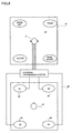
- Fig. 8 is a schematic view showing 4-channel sound collection with the microphone unit and 4-channel sound reproduction.
- the microphone unit A was placed, a drum set, piano, guitar and a base guitar were placed at a front left, front right, rear left and rear right, respectively for sound collection.
- the speaker units 83, 84, 85 and 86 were placed at a front left, front right, rear left and rear right, respectively.
- a listener 87 was expected to listen to the sound in the center of the room 82.
- the listener 87 heard the drum sound from the front left, piano sound from the front right, guitar sound from the rear left and the base guitar sound from the rear right.
- the sounds derived from reproducing those collected sounds through 4 channels were found to be substantially stereophonic owing to stable sound field.
- Described hereinafter is with respect to the sound reproduction with a headphone by converting 4-channel sound collected with the microphone unit into the 2-channel sound.
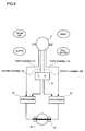
- Fig. 9 is a schematic view showing a mechanism in which the sound is collected with the microphone unit A via 4 channels and the collected sound is converted into 2-channel sound with the channel conversion system for sound reproduction with the headphone.
- one channel for picking up the front left sound was designated as a first channel F/L.
- the other channel for picking up the rear left sound was designated as a second channel R/L.
- one channel for picking up the front right sound was designated as a third channel F/R.
- the other channel for picking up the rear right sound was designated as a fourth channel R/R.
- the sounds received by the second channel R/L and the fourth channel R/R were input to an equalizer 31.
- the equalizer 31 corrected the frequency of each input sound, R/L sound and R/R sound, by rendering those sounds to have the characteristic as shown in Fig. 4.
- the second channel R/L sound was synthesized with the first channel F/L sound in a synthesizer 32.
- the fourth channel R/R sound was synthesized with the third channel F/R sound in a synthesizer 33.
- the 2-channel sound converted from the 4-channel sound was heard through the headphone 91.
- the reproduced sound had far more excellent quality in stereophonic aspect than those reproduced through a conventional stereo mode.
- the listener 92 listened to the sound of each instrument separately, i.e., the drum sound from the front left, the piano sound from the front right, the guitar sound from the rear left and the base guitar sound from the rear right, respectively.
- Described is a process for collecting the sound by the microphone unit and processing the collected sound through a channel conversion system and a sound processing system.
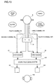
- Fig. 10 is a schematic view showing a mechanism where the sound is collected by the microphone unit and the collected sound is processed through the channel conversion system and the sound processing system.
- the microphone unit A collected sounds through 4 channels. Then the collected sound was converted into 2-channel sound through the channel conversion system, which was further processed through the sound processing system 100.
- delay circuits 53 1 , 53 2 , 54 1 and 54 2 were used. In each delay circuit 53 1 and 54 1 , 0.5 msec. was set as the delay time. In each delay circuit 53 2 and 54 2 , 1.0 msec. was set as the delay time. Supposing that the volume level ratio of the channel signal was 1, the synthesizers 55 and 56 were designed to synthesize the output signals of the difference signal generation circuit and the delay circuit so that the total volume level ratio became 0.6.
- the reproduced sound was found to have the sound field with the similar stereophonic sound to that heard through the headphone.
- a listener 103 heard the sound of each instrument distinctly, that was the drum sound from the front left, piano sound from the front right, guitar sound from the rear left and base guitar sound from the rear right.
- the microphone unit using 4 channels gave the most excellent reproduced sound.
- frequency correction through converting the sound into 2-channel also allowed for an excellent reproduced sound field which never has been offered by the conventional stereo mode. Additionally the above frequency correction did not require a great deal of labor.
- the thus processed sound was recorded on the tape and then reproduced.
- the resultant sound field presented excellent quality in view of reality equivalent to the aforementioned effect.
- the sound is recorded by a 2-channel (track) tape recorder after being collected and processed.
- the collected sound is recorded by a 4-channel (track) tape recorder, processed and then recorded by the 2-channel (track) tape recorder.
- the recording medium is not limited to a magnetic tape.
- a record, CD or the like are available.
- Employing a stereo mode (2-channel) enables the AM radio broadcasting to offer a reproduction of the real sound field as excellent as the FM radio broadcast.
- the present invention allows both 2-channel reproduction and 4-channel reproduction to provide excellent stereophonic and real sounds, which is an advantageous art for an acoustic field.
Landscapes
- Physics & Mathematics (AREA)
- Engineering & Computer Science (AREA)
- Acoustics & Sound (AREA)
- Signal Processing (AREA)
- Stereophonic System (AREA)
Applications Claiming Priority (1)
| Application Number | Priority Date | Filing Date | Title |
|---|---|---|---|
| PCT/JP1996/000939 WO1997038553A1 (fr) | 1996-04-05 | 1996-04-05 | Systeme acoustique |
Publications (1)
| Publication Number | Publication Date |
|---|---|
| EP0848572A1 true EP0848572A1 (fr) | 1998-06-17 |
Family
ID=14153165
Family Applications (1)
| Application Number | Title | Priority Date | Filing Date |
|---|---|---|---|
| EP96908354A Withdrawn EP0848572A1 (fr) | 1996-04-05 | 1996-04-05 | Systeme acoustique |
Country Status (2)
| Country | Link |
|---|---|
| EP (1) | EP0848572A1 (fr) |
| WO (1) | WO1997038553A1 (fr) |
Cited By (5)
| Publication number | Priority date | Publication date | Assignee | Title |
|---|---|---|---|---|
| FR2854537A1 (fr) * | 2003-04-29 | 2004-11-05 | Hong Cong Tuyen Pham | Casque acoustique pour la restitution spatiale d'un son. |
| US6851512B2 (en) | 2002-03-01 | 2005-02-08 | Charles Whitman Fox | Modular microphone array for surround sound recording |
| WO2006096959A1 (fr) * | 2005-03-16 | 2006-09-21 | James Cox | Ensemble de microphones et systeme de traitement numerique des signaux |
| US20140163311A1 (en) * | 2005-01-13 | 2014-06-12 | Louis Fisher Davis, Jr. | Method and apparatus for ambient sound therapy user interface and control system |
| CN107071657A (zh) * | 2005-01-13 | 2017-08-18 | 环境医疗有限责任公司 | 环境疗法记录与回放系统和记录与回放治疗音频的方法 |
Families Citing this family (2)
| Publication number | Priority date | Publication date | Assignee | Title |
|---|---|---|---|---|
| JP4663085B2 (ja) * | 2000-09-19 | 2011-03-30 | パナソニック株式会社 | 音響再生装置 |
| JP2005198251A (ja) * | 2003-12-29 | 2005-07-21 | Korea Electronics Telecommun | 球体を用いた3次元オーディオ信号処理システム及びその方法 |
Family Cites Families (3)
| Publication number | Priority date | Publication date | Assignee | Title |
|---|---|---|---|---|
| JPS5289001U (fr) * | 1975-12-25 | 1977-07-02 | ||
| JPS5843959B2 (ja) * | 1977-04-04 | 1983-09-30 | 日本ビクター株式会社 | バイノ−ラル信号収録装置 |
| JPS53140002A (en) * | 1977-05-13 | 1978-12-06 | Victor Co Of Japan Ltd | Echo adding device for stereophonic acoustic reproducing system of two channel type |
-
1996
- 1996-04-05 EP EP96908354A patent/EP0848572A1/fr not_active Withdrawn
- 1996-04-05 WO PCT/JP1996/000939 patent/WO1997038553A1/fr not_active Ceased
Non-Patent Citations (1)
| Title |
|---|
| See references of WO9738553A1 * |
Cited By (12)
| Publication number | Priority date | Publication date | Assignee | Title |
|---|---|---|---|---|
| US6851512B2 (en) | 2002-03-01 | 2005-02-08 | Charles Whitman Fox | Modular microphone array for surround sound recording |
| FR2854537A1 (fr) * | 2003-04-29 | 2004-11-05 | Hong Cong Tuyen Pham | Casque acoustique pour la restitution spatiale d'un son. |
| WO2004098235A1 (fr) * | 2003-04-29 | 2004-11-11 | Pham Hong Cong Tuyen | Casque acoustique pour la restitution spatiale d’un son. |
| US7532734B2 (en) | 2003-04-29 | 2009-05-12 | Pham Hong Cong Tuyen | Headphone for spatial sound reproduction |
| CN1781336B (zh) * | 2003-04-29 | 2012-06-27 | 洪·崇·图延·费姆 | 立体声再现的头戴收发话器 |
| US20140163311A1 (en) * | 2005-01-13 | 2014-06-12 | Louis Fisher Davis, Jr. | Method and apparatus for ambient sound therapy user interface and control system |
| US20170056615A1 (en) * | 2005-01-13 | 2017-03-02 | Louis Fisher Davis, Jr. | Method and apparatus for ambient sound therapy user interface and control system |
| CN107071657A (zh) * | 2005-01-13 | 2017-08-18 | 环境医疗有限责任公司 | 环境疗法记录与回放系统和记录与回放治疗音频的方法 |
| US10166361B2 (en) * | 2005-01-13 | 2019-01-01 | Louis Fisher Davis, Jr. | Method and apparatus for ambient sound therapy user interface and control system |
| US10456551B2 (en) * | 2005-01-13 | 2019-10-29 | Louis Fisher Davis, Jr. | Method and apparatus for ambient sound therapy user interface and control system |
| WO2006096959A1 (fr) * | 2005-03-16 | 2006-09-21 | James Cox | Ensemble de microphones et systeme de traitement numerique des signaux |
| US8090117B2 (en) | 2005-03-16 | 2012-01-03 | James Cox | Microphone array and digital signal processing system |
Also Published As
| Publication number | Publication date |
|---|---|
| WO1997038553A1 (fr) | 1997-10-16 |
Similar Documents
| Publication | Publication Date | Title |
|---|---|---|
| JP3435156B2 (ja) | 音像定位装置 | |
| US8027476B2 (en) | Sound reproduction apparatus and sound reproduction method | |
| US6763115B1 (en) | Processing method for localization of acoustic image for audio signals for the left and right ears | |
| JP3435141B2 (ja) | 音像定位装置、並びに音像定位装置を用いた会議装置、携帯電話機、音声再生装置、音声記録装置、情報端末装置、ゲーム機、通信および放送システム | |
| US20050281421A1 (en) | First person acoustic environment system and method | |
| US20080118078A1 (en) | Acoustic system, acoustic apparatus, and optimum sound field generation method | |
| US8442244B1 (en) | Surround sound system | |
| CA1068612A (fr) | Circuit de casque simulant les signaux de reverberation | |
| US9111523B2 (en) | Device for and a method of processing a signal | |
| KR20140053831A (ko) | 완전한 오디오 신호를 위한 장치 및 방법 | |
| JP2007195092A (ja) | 音響再生装置および音響再生方法 | |
| JP5281695B2 (ja) | 音響変換装置 | |
| JP2006303658A (ja) | 再生装置および再生方法 | |
| US20050190936A1 (en) | Sound pickup apparatus, sound pickup method, and recording medium | |
| KR20120088703A (ko) | 완전 오디오 신호를 위한 위상 계층화 장치 및 방법 | |
| WO1997038553A1 (fr) | Systeme acoustique | |
| CN110099351B (zh) | 一种声场回放方法、装置和系统 | |
| JPH0847078A (ja) | 車室内周波数特性自動補正方法 | |
| JP2002291100A (ja) | オーディオ信号再生方法、及びパッケージメディア | |
| JPH06217400A (ja) | 音響装置 | |
| JP2005328315A (ja) | 音響装置および記録方法 | |
| JPH06269097A (ja) | 音響装置 | |
| CN223967968U (zh) | 一种组合式音响系统 | |
| JP2003032782A (ja) | 音響再生装置 | |
| JPWO1997038553A1 (ja) | 音響システム |
Legal Events
| Date | Code | Title | Description |
|---|---|---|---|
| PUAI | Public reference made under article 153(3) epc to a published international application that has entered the european phase |
Free format text: ORIGINAL CODE: 0009012 |
|
| 17P | Request for examination filed |
Effective date: 19971204 |
|
| AK | Designated contracting states |
Kind code of ref document: A1 Designated state(s): AT CH DE FR GB IT LI NL SE |
|
| STAA | Information on the status of an ep patent application or granted ep patent |
Free format text: STATUS: THE APPLICATION IS DEEMED TO BE WITHDRAWN |
|
| 18D | Application deemed to be withdrawn |
Effective date: 19991103 |