EP0848623B1 - Injektionsgerät zum injizieren von flüssigkeit - Google Patents
Injektionsgerät zum injizieren von flüssigkeit Download PDFInfo
- Publication number
- EP0848623B1 EP0848623B1 EP96920674A EP96920674A EP0848623B1 EP 0848623 B1 EP0848623 B1 EP 0848623B1 EP 96920674 A EP96920674 A EP 96920674A EP 96920674 A EP96920674 A EP 96920674A EP 0848623 B1 EP0848623 B1 EP 0848623B1
- Authority
- EP
- European Patent Office
- Prior art keywords
- injection device
- threaded nut
- driven member
- coupling part
- threaded
- Prior art date
- Legal status (The legal status is an assumption and is not a legal conclusion. Google has not performed a legal analysis and makes no representation as to the accuracy of the status listed.)
- Expired - Lifetime
Links
- 238000002347 injection Methods 0.000 title claims abstract description 25
- 239000007924 injection Substances 0.000 title claims abstract description 25
- 239000007788 liquid Substances 0.000 title claims description 13
- 230000008878 coupling Effects 0.000 claims description 34
- 238000010168 coupling process Methods 0.000 claims description 34
- 238000005859 coupling reaction Methods 0.000 claims description 34
- 230000003213 activating effect Effects 0.000 claims 2
- 239000012530 fluid Substances 0.000 abstract description 3
- 230000007246 mechanism Effects 0.000 description 9
- 239000003708 ampul Substances 0.000 description 4
- 238000009826 distribution Methods 0.000 description 4
- 239000003814 drug Substances 0.000 description 2
- 230000002730 additional effect Effects 0.000 description 1
- 230000008859 change Effects 0.000 description 1
- 238000006073 displacement reaction Methods 0.000 description 1
- 229940079593 drug Drugs 0.000 description 1
- 230000036541 health Effects 0.000 description 1
- 230000013011 mating Effects 0.000 description 1
- 238000000034 method Methods 0.000 description 1
- 230000008569 process Effects 0.000 description 1
Images


Classifications
-
- A—HUMAN NECESSITIES
- A61—MEDICAL OR VETERINARY SCIENCE; HYGIENE
- A61M—DEVICES FOR INTRODUCING MEDIA INTO, OR ONTO, THE BODY; DEVICES FOR TRANSDUCING BODY MEDIA OR FOR TAKING MEDIA FROM THE BODY; DEVICES FOR PRODUCING OR ENDING SLEEP OR STUPOR
- A61M5/00—Devices for bringing media into the body in a subcutaneous, intra-vascular or intramuscular way; Accessories therefor, e.g. filling or cleaning devices, arm-rests
- A61M5/178—Syringes
- A61M5/31—Details
- A61M5/315—Pistons; Piston-rods; Guiding, blocking or restricting the movement of the rod or piston; Appliances on the rod for facilitating dosing ; Dosing mechanisms
- A61M5/31565—Administration mechanisms, i.e. constructional features, modes of administering a dose
- A61M5/31576—Constructional features or modes of drive mechanisms for piston rods
- A61M5/31578—Constructional features or modes of drive mechanisms for piston rods based on axial translation, i.e. components directly operatively associated and axially moved with plunger rod
- A61M5/3158—Constructional features or modes of drive mechanisms for piston rods based on axial translation, i.e. components directly operatively associated and axially moved with plunger rod performed by axially moving actuator operated by user, e.g. an injection button
-
- A—HUMAN NECESSITIES
- A61—MEDICAL OR VETERINARY SCIENCE; HYGIENE
- A61M—DEVICES FOR INTRODUCING MEDIA INTO, OR ONTO, THE BODY; DEVICES FOR TRANSDUCING BODY MEDIA OR FOR TAKING MEDIA FROM THE BODY; DEVICES FOR PRODUCING OR ENDING SLEEP OR STUPOR
- A61M5/00—Devices for bringing media into the body in a subcutaneous, intra-vascular or intramuscular way; Accessories therefor, e.g. filling or cleaning devices, arm-rests
- A61M5/178—Syringes
- A61M5/24—Ampoule syringes, i.e. syringes with needle for use in combination with replaceable ampoules or carpules, e.g. automatic
-
- A—HUMAN NECESSITIES
- A61—MEDICAL OR VETERINARY SCIENCE; HYGIENE
- A61M—DEVICES FOR INTRODUCING MEDIA INTO, OR ONTO, THE BODY; DEVICES FOR TRANSDUCING BODY MEDIA OR FOR TAKING MEDIA FROM THE BODY; DEVICES FOR PRODUCING OR ENDING SLEEP OR STUPOR
- A61M5/00—Devices for bringing media into the body in a subcutaneous, intra-vascular or intramuscular way; Accessories therefor, e.g. filling or cleaning devices, arm-rests
- A61M5/178—Syringes
- A61M5/31—Details
- A61M5/315—Pistons; Piston-rods; Guiding, blocking or restricting the movement of the rod or piston; Appliances on the rod for facilitating dosing ; Dosing mechanisms
- A61M5/31533—Dosing mechanisms, i.e. setting a dose
- A61M5/31545—Setting modes for dosing
- A61M5/31548—Mechanically operated dose setting member
- A61M5/3155—Mechanically operated dose setting member by rotational movement of dose setting member, e.g. during setting or filling of a syringe
- A61M5/31553—Mechanically operated dose setting member by rotational movement of dose setting member, e.g. during setting or filling of a syringe without axial movement of dose setting member
-
- A—HUMAN NECESSITIES
- A61—MEDICAL OR VETERINARY SCIENCE; HYGIENE
- A61M—DEVICES FOR INTRODUCING MEDIA INTO, OR ONTO, THE BODY; DEVICES FOR TRANSDUCING BODY MEDIA OR FOR TAKING MEDIA FROM THE BODY; DEVICES FOR PRODUCING OR ENDING SLEEP OR STUPOR
- A61M5/00—Devices for bringing media into the body in a subcutaneous, intra-vascular or intramuscular way; Accessories therefor, e.g. filling or cleaning devices, arm-rests
- A61M5/178—Syringes
- A61M5/24—Ampoule syringes, i.e. syringes with needle for use in combination with replaceable ampoules or carpules, e.g. automatic
- A61M2005/2403—Ampoule inserted into the ampoule holder
- A61M2005/2407—Ampoule inserted into the ampoule holder from the rear
-
- A—HUMAN NECESSITIES
- A61—MEDICAL OR VETERINARY SCIENCE; HYGIENE
- A61M—DEVICES FOR INTRODUCING MEDIA INTO, OR ONTO, THE BODY; DEVICES FOR TRANSDUCING BODY MEDIA OR FOR TAKING MEDIA FROM THE BODY; DEVICES FOR PRODUCING OR ENDING SLEEP OR STUPOR
- A61M5/00—Devices for bringing media into the body in a subcutaneous, intra-vascular or intramuscular way; Accessories therefor, e.g. filling or cleaning devices, arm-rests
- A61M5/178—Syringes
- A61M5/31—Details
- A61M5/315—Pistons; Piston-rods; Guiding, blocking or restricting the movement of the rod or piston; Appliances on the rod for facilitating dosing ; Dosing mechanisms
- A61M5/31533—Dosing mechanisms, i.e. setting a dose
- A61M5/31535—Means improving security or handling thereof, e.g. blocking means, means preventing insufficient dosing, means allowing correction of overset dose
- A61M5/31543—Means improving security or handling thereof, e.g. blocking means, means preventing insufficient dosing, means allowing correction of overset dose piston rod reset means, i.e. means for causing or facilitating retraction of piston rod to its starting position during cartridge change
-
- A—HUMAN NECESSITIES
- A61—MEDICAL OR VETERINARY SCIENCE; HYGIENE
- A61M—DEVICES FOR INTRODUCING MEDIA INTO, OR ONTO, THE BODY; DEVICES FOR TRANSDUCING BODY MEDIA OR FOR TAKING MEDIA FROM THE BODY; DEVICES FOR PRODUCING OR ENDING SLEEP OR STUPOR
- A61M5/00—Devices for bringing media into the body in a subcutaneous, intra-vascular or intramuscular way; Accessories therefor, e.g. filling or cleaning devices, arm-rests
- A61M5/178—Syringes
- A61M5/31—Details
- A61M5/315—Pistons; Piston-rods; Guiding, blocking or restricting the movement of the rod or piston; Appliances on the rod for facilitating dosing ; Dosing mechanisms
- A61M5/31533—Dosing mechanisms, i.e. setting a dose
- A61M5/31545—Setting modes for dosing
- A61M5/31548—Mechanically operated dose setting member
- A61M5/31563—Mechanically operated dose setting member interacting with a displaceable stop member
-
- A—HUMAN NECESSITIES
- A61—MEDICAL OR VETERINARY SCIENCE; HYGIENE
- A61M—DEVICES FOR INTRODUCING MEDIA INTO, OR ONTO, THE BODY; DEVICES FOR TRANSDUCING BODY MEDIA OR FOR TAKING MEDIA FROM THE BODY; DEVICES FOR PRODUCING OR ENDING SLEEP OR STUPOR
- A61M5/00—Devices for bringing media into the body in a subcutaneous, intra-vascular or intramuscular way; Accessories therefor, e.g. filling or cleaning devices, arm-rests
- A61M5/178—Syringes
- A61M5/31—Details
- A61M5/315—Pistons; Piston-rods; Guiding, blocking or restricting the movement of the rod or piston; Appliances on the rod for facilitating dosing ; Dosing mechanisms
- A61M5/31565—Administration mechanisms, i.e. constructional features, modes of administering a dose
- A61M5/31576—Constructional features or modes of drive mechanisms for piston rods
- A61M5/31583—Constructional features or modes of drive mechanisms for piston rods based on rotational translation, i.e. movement of piston rod is caused by relative rotation between the user activated actuator and the piston rod
- A61M5/31585—Constructional features or modes of drive mechanisms for piston rods based on rotational translation, i.e. movement of piston rod is caused by relative rotation between the user activated actuator and the piston rod performed by axially moving actuator, e.g. an injection button
Definitions
- the present invention relates to a Injection device for injecting liquid according to the Preamble of claim 1.
- Syringe-shaped injection devices for injecting liquids have been known for a long time. They have a sleeve-shaped main body that can be screwed together approximately in the middle and can be divided into two main areas: a proximal area (facing away from the patient) containing the delivery mechanism, at least consisting of a rod-shaped output member with a structured surface, for example a screw spindle, a hollow cylindrical mating element with a structured inner jacket, for example a screw nut, for the output member, and an operating button; and a distal area (facing the patient) in which the liquid to be administered and a movable plunger are located.
- a proximal area facing away from the patient
- the delivery mechanism at least consisting of a rod-shaped output member with a structured surface, for example a screw spindle, a hollow cylindrical mating element with a structured inner jacket, for example a screw nut, for the output member, and an operating button
- a distal area facing the patient in which the liquid to
- a needle is attached to the distal end of the main body Needle holder placed, which the discharge of the Allows liquid from the device; known such Needles are e.g. PENFINE® needles, as in WO 95/01812 described.
- Link between the proximal and distal area of the main body is the driven member, which pushes the plunger into the distal by the selected dose Pushes direction, causing the liquid to eject the needle is leading.
- the liquid to be administered is not there directly in the main body, but in an ampoule, the Liquid between a vial and one slidable piston is mounted.
- the dispensing mechanism Different expected. There are devices that only a single distribution, such as several of the same size Distributions and those that have multiple freely selectable Allow distributions.
- the invention is based on the object Injection device with a resettable output member create with which with greater certainty than with known devices an accidental reset of the Output member is prevented.
- the invention solves the problem with an injection device, which has the features of claim 1.
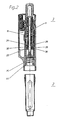
- a needle 6 can be screwed on, its proximal End in connection with the liquid to be administered stands.
- the actuating device 7 has an operating button 8, a rod-shaped output member 9 in the form of a Threaded rod with a flange 19, a guide element 24 and a hollow cylindrical counter element 11 in the form of a Drive element on.
- the output member 9 is in the following referred to as threaded rod 9.
- the tubular drive element 11 is with the control button 8 firmly connected against rotation. It points at the distal end a split threaded nut 27, which in the thread of Threaded rod 9 engages.
- the threaded rod 9 is inside of the drive element 11 mounted.
- the threaded rod 9 two has opposite, plane surfaces 12, 12 ', otherwise but has a circular cross-section and on the circular sections 13,13 'carries a thread.
- the guide element 24 is both against rotational movements as well as against axial displacements with the Mechanism holder 10 and thus with the sleeve-shaped body 1 connected and lies in front of the drive element 11.
- the opening in the guide element 24 through which the threaded rod 9 passes through has the same cross-section - around one certain tolerance increases, such as the cross section of the Threaded rod 9. Since the guide element 24 - in contrast to the drive element 11 - has no thread, the Threaded rod 9 through this opening of the guide element 24 be pushed back and forth in the axial direction. A Rotational movement of the threaded rod 9 is therefore not possible because this does not allow the guide element 24.
- the threaded rod 9 is connected to the drive element 11 through the Threaded segments 31, 31 ', 32, 32' connected so that axial Movements of the control button 8 can be transmitted.
- the rotating threaded nut 27 of the drive element 11 drives the threaded rod 13 over the threaded segments 31, 31 ', 32, 32' on the threaded sections 13, 13 'of the threaded rod 9 in a rotationally fixed manner to the front (or when the control knob 8 is rotated in the opposite direction), and thus brought the flange 19 into the position which requires the next dose to be dispensed, ie the distance of the flange 19 from the piston 5 is reduced accordingly.
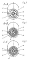
- the injection device 1 now allows one Pushing back the threaded rod 9. From FIGS. 1-5 it can be seen that the thread of the drive element 11 horizontally with respect to the longitudinal axis 55 in two sleeve-shaped threaded nut halves 28,29 is divided. A Pushing back the threaded rod 9 is made possible that the threaded nut halves 28, 29 engage standing threaded portions 13,13 'of the threaded rod 9 from the threaded nut halves 28, 29 are loosened.
- Threaded nut halves 28, 29 have two thread segments 31.31 ', 32.32' on which of the smooth inner surfaces 33, 33 ', 34, 34' protrude.
- always two thread segments (90 °) 31, 31 ', 32, 32' face each other. Every 90 ° Thread segment 31.31 ', 32.32' follows a 90 ° smoother Section 33,33 ', 34,34'.
- the two threaded nut halves 28,29 are in the operating state against each other by 90 ° moved so that the threaded rod 9 in total of 360 ° thread is surrounded.
- the external thread of the Threaded rod 9 is therefore temporarily only with two thread segments of one or the other nut half 28, 29 engaged. As shown below this intervention is only two Thread segments into the external thread of the threaded rod 9 essential for the possibility of pushing back the Threaded rod 9.
- the two sleeve-shaped threaded nut halves 28, 29 are surrounded by a sleeve-shaped coupling part 38.
- a sleeve-shaped coupling part 38 there corresponds to the inside diameter of the coupling part 38 Outside diameter of the threaded nut halves 28.29, so that the coupling part 38 via the threaded nut halves 28, 29 can slide.
- the Coupling part 38 has an inner cam 39, which in an incision 40 on the outer surfaces of the Threaded nut halves 28,29 engages.
- the proximal nut half 29 is with the Drive element 11 rotatably connected, so that each Rotational movement of the drive element 11 immediately on the proximal nut half 29 is transmitted. This Movement is applied to the distal by means of the coupling part 38 Transfer threaded nut half 28. An axial movement of the Drive elements 11 is on the spring 17 on the two Transfer nut halves 28,29.
- the coupling part 38 is between a proximal and a distal position axially displaceable.
- the proximal position corresponds to the apparent from Fig. 1 operating position
- the distal position is that shown in FIG. 2 Position.
- the threaded rod can even in the position shown in Fig. 2 still from the distal threaded nut.
- the coupling part 38 is located in its proximal Position, the two nut halves are 28.29 ⁇ m Twisted 90 ° coupled and thus the threaded rod 9 of Surround 360 ° thread. However, this is Coupling part 38 in its distal position are the both threaded nut halves 28, 29 can be rotated by 90 °, i.e. releasable from engagement with the threaded rod 9.
- the slide 44 and the coupling part 38 are in proximal position (Fig. 1), touch two at the distal Front side 43 of the coupling part 38 attached cams 45,46 the mechanism holder 10 are located in the mechanism holder 10 two openings 47 and 48 through two extensions of the slide 44 are filled and thereby prevent that the two cams 45, 46 can slide in the distal position.
- the two openings 47, 48 are arranged such that the Coupling sleeve formed coupling part 38 only in the distal position can slide when the nut segments 31, 31 'of the distal threaded nut half 28 does not engage with the threaded rod 9.
- the slide 44 is by the pressure of the spring 16th via the coupling part 38 in its front stop pushed when the two cams 45.46 of the Coupling part 38 over the openings 47,48 of the Mechanism holder 10 are.
- the coupling part 38 can only in slide its distal position and at the same time the pusher 44 push in the distal direction when the two Cams 45, 46 of the coupling part 38 over the openings 47,48 of the mechanism holder 10 are.
- the Slide 44 and the coupling part 38 in the distal position causes the control knob 8 to be rotated by 90 ° Direction of normal dosing to a twist the proximal nut half 29 by 90 °, i.e.
- the two threaded nut halves 28, 29 are located on the other hand not and will not be rotated by 90 ° nevertheless tried the two main areas 2,3 into each other, the slide 44 can not in be pushed proximally because of the inner cam 39 of the coupling part 38 in the incision 41 of the proximal Thread nut half 29 is. It is therefore not possible in such a position of the two Threaded nut halves 28,29 the two main areas 2,3 completely fit together. To the patient on it to draw attention to the fact that the injection device is not is operational, that part of the two Main areas, which is normally not visible, but visible through the incomplete assembly remains to be discolored.
Landscapes
- Health & Medical Sciences (AREA)
- Vascular Medicine (AREA)
- Engineering & Computer Science (AREA)
- Anesthesiology (AREA)
- Biomedical Technology (AREA)
- Heart & Thoracic Surgery (AREA)
- Hematology (AREA)
- Life Sciences & Earth Sciences (AREA)
- Animal Behavior & Ethology (AREA)
- General Health & Medical Sciences (AREA)
- Public Health (AREA)
- Veterinary Medicine (AREA)
- Infusion, Injection, And Reservoir Apparatuses (AREA)
- Consolidation Of Soil By Introduction Of Solidifying Substances Into Soil (AREA)
- Nozzles (AREA)
Applications Claiming Priority (1)
| Application Number | Priority Date | Filing Date | Title |
|---|---|---|---|
| PCT/CH1996/000248 WO1998001171A1 (de) | 1996-07-05 | 1996-07-05 | Injektionsgerät zum injizieren von flüssigkeit |
Publications (2)
| Publication Number | Publication Date |
|---|---|
| EP0848623A1 EP0848623A1 (de) | 1998-06-24 |
| EP0848623B1 true EP0848623B1 (de) | 2003-10-08 |
Family
ID=4550434
Family Applications (1)
| Application Number | Title | Priority Date | Filing Date |
|---|---|---|---|
| EP96920674A Expired - Lifetime EP0848623B1 (de) | 1996-07-05 | 1996-07-05 | Injektionsgerät zum injizieren von flüssigkeit |
Country Status (6)
| Country | Link |
|---|---|
| US (1) | US6413242B1 (da) |
| EP (1) | EP0848623B1 (da) |
| AT (1) | ATE251479T1 (da) |
| DE (1) | DE59610766D1 (da) |
| DK (1) | DK0848623T3 (da) |
| WO (1) | WO1998001171A1 (da) |
Families Citing this family (12)
| Publication number | Priority date | Publication date | Assignee | Title |
|---|---|---|---|---|
| US6221053B1 (en) * | 1998-02-20 | 2001-04-24 | Becton, Dickinson And Company | Multi-featured medication delivery pen |
| US6205280B1 (en) | 1998-08-25 | 2001-03-20 | Molecular Optoelectronics Corporation | Blockless fiber optic attenuators and attenuation systems employing dispersion controlled polymers |
| DE29818721U1 (de) * | 1998-10-21 | 2000-03-02 | Medico Development Investment Co., Ascona | Injektionsgerät |
| DE10009816A1 (de) * | 2000-03-01 | 2001-10-18 | Disetronic Licensing Ag | Nadelschutzvorrichtung für ein Injektionsgerät |
| DE10221783A1 (de) * | 2002-05-15 | 2003-12-04 | Aventis Pharma Gmbh | Vorrichtung zur Führung eines Antriebes |
| DE10326766B4 (de) | 2003-06-13 | 2005-10-27 | Disetronic Licensing Ag | Antriebsvorrichtung zum Vorschub eines Vorschubelements und Verfahren zur Ausschüttung eines fluiden Produkts aus einem Behälter |
| DE20317377U1 (de) * | 2003-11-03 | 2005-03-17 | B D Medico S A R L | Injektionsgerät |
| CN101039713B (zh) * | 2004-10-14 | 2011-10-12 | 诺和诺德公司 | 具有剂量机构的注射装置 |
| US8801689B2 (en) | 2007-08-01 | 2014-08-12 | Hospira, Inc. | Medicament admixing system |
| US9623187B2 (en) * | 2009-06-01 | 2017-04-18 | Sanofi-Aventis Deutschland Gmbh | Resettable drug delivery device |
| US8721612B2 (en) | 2010-12-17 | 2014-05-13 | Hospira, Inc. | System and method for intermixing the contents of two containers |
| US8882739B2 (en) | 2011-10-03 | 2014-11-11 | Hospira, Inc. | System and method for mixing the contents of two containers |
Family Cites Families (55)
| Publication number | Priority date | Publication date | Assignee | Title |
|---|---|---|---|---|
| DE3163728D1 (en) | 1980-04-08 | 1984-06-28 | Greater Glasgow Health Board | Dispensing device |
| GB2109690B (en) | 1981-02-12 | 1985-02-20 | Robert Charles Turner | Dose metering plunger devices for use with syringes |
| DE3468173D1 (en) | 1983-09-07 | 1988-02-04 | Disetronic Ag | Portable infusion apparatus |
| US4592745A (en) | 1984-02-29 | 1986-06-03 | Novo Industri A/S | Dispenser |
| EP0256024A1 (en) | 1985-11-08 | 1988-02-24 | Exfluor Research Corporation | The pyrolysis of perfluoropolyethers |
| BR8606965A (pt) | 1985-11-08 | 1987-11-03 | Disetronic Ag | Aparelho injetor |
| DE3645245C2 (de) | 1986-11-14 | 1994-01-27 | Haselmeier Wilhelm Fa | Injektionsgerät |
| DK177187A (da) | 1987-04-07 | 1988-10-08 | Dcp Af 1988 As | Doseringsenhed til dosering af et antal afmaalte maengder af en vaeske, saasom insulin, fra en glasampul |
| GB8713810D0 (en) | 1987-06-12 | 1987-07-15 | Hypoguard Uk Ltd | Measured dose dispensing device |
| IL86799A (en) | 1987-07-02 | 1993-03-15 | Kabi Pharmacia Ab | Method and device for injection |
| DE3900926C2 (de) | 1988-02-08 | 1999-05-12 | Disetronic Licensing Ag | Spritzenförmiges Injektionsgerät und Injektionsgerätebaukasten |
| DK166948B1 (da) | 1988-02-10 | 1993-08-09 | Dcp Af 1988 As | Doseringsenhed til dosering af et antal afmaalte maengder af en vaeske, saasom insulin, fra en glastubule |
| US4973318A (en) | 1988-02-10 | 1990-11-27 | D.C.P. Af 1988 A/S | Disposable syringe |
| GB8809115D0 (en) | 1988-04-18 | 1988-05-18 | Turner R C | Syringes |
| CH680904A5 (da) | 1988-10-19 | 1992-12-15 | Disetronic Ag | |
| US5084060A (en) | 1989-02-15 | 1992-01-28 | Freund Precision, Inc. | Apparatus for enlarging a vessel or clearing obstructive tissue from a vessel according to vessel compliance |
| US4946446A (en) | 1989-06-14 | 1990-08-07 | Vadher Dinesh L | Retractable needle |
| DK17890A (da) | 1990-01-22 | 1991-07-23 | Novo Nordisk As | Fremgangsmaade og apparat til opblanding og injicering af et laegemiddel |
| US5226896A (en) | 1990-04-04 | 1993-07-13 | Eli Lilly And Company | Dose indicating injection pen |
| US5222947A (en) | 1990-04-18 | 1993-06-29 | Amico Elio D | Self recapping injection needle assembly |
| AU641206B2 (en) | 1991-01-22 | 1993-09-16 | Eli Lilly And Company | Multiple dose injection pen |
| DE69203472T2 (de) | 1991-02-07 | 1996-01-04 | Terumo Corp | Dosiereinrichtung für Injektor. |
| DE4112259A1 (de) | 1991-04-15 | 1992-10-22 | Medico Dev Investment Co | Injektionsgeraet |
| GB9111600D0 (en) | 1991-05-30 | 1991-07-24 | Owen Mumford Ltd | Improvements relating to injection devices |
| EP0518416A1 (en) | 1991-06-13 | 1992-12-16 | Duphar International Research B.V | Injection device |
| EP0525525B1 (de) | 1991-07-24 | 1995-05-03 | Medico Development Investment Company | Injektor |
| SE9102652D0 (sv) | 1991-09-13 | 1991-09-13 | Kabi Pharmacia Ab | Injection needle arrangement |
| US5279585A (en) | 1992-02-04 | 1994-01-18 | Becton, Dickinson And Company | Medication delivery pen having improved dose delivery features |
| CH682806A5 (de) * | 1992-02-21 | 1993-11-30 | Medimpex Ets | Injektionsgerät. |
| US5545147A (en) | 1992-10-20 | 1996-08-13 | Eli Lilly And Company | Anti-backup improvement for hypodermic syringes |
| US5295975A (en) | 1992-10-28 | 1994-03-22 | Lockwood Jr Hanford N | Hypodermic needle safety device with sliding outer cover |
| US5320609A (en) | 1992-12-07 | 1994-06-14 | Habley Medical Technology Corporation | Automatic pharmaceutical dispensing syringe |
| US5338430A (en) | 1992-12-23 | 1994-08-16 | Minnesota Mining And Manufacturing Company | Nanostructured electrode membranes |
| FR2701211B1 (fr) | 1993-02-08 | 1995-05-24 | Aguettant Lab | Instrument doseur, notamment d'injection |
| US5292314A (en) | 1993-02-11 | 1994-03-08 | International Medical Consultants, Inc. | Automatic needle protector |
| CH688225A5 (de) | 1993-06-04 | 1997-06-30 | Medimpex Ets | Vorschubvorrichtung fuer eine Injektionsvorrichtung. |
| GB9310163D0 (en) | 1993-05-18 | 1993-06-30 | Owen Mumford Ltd | Improvements relating to injection devices |
| US5527294A (en) | 1993-05-18 | 1996-06-18 | Safety 1St | Shielded syringe |
| CH685677A5 (de) | 1993-07-09 | 1995-09-15 | Disetronic Ag | Befestigungsmechanismus für Nadelsysteme. |
| GB9316692D0 (en) | 1993-08-11 | 1993-09-29 | Smithkline Beecham Plc | Novel device |
| US5472430A (en) | 1993-08-18 | 1995-12-05 | Vlv Associates | Protected needle assembly |
| US5338311A (en) | 1993-08-23 | 1994-08-16 | Mahurkar Sakharam D | Hypodermic needle assembly |
| US5336183A (en) | 1993-09-28 | 1994-08-09 | Imagyn Medical, Inc. | Inflator |
| US5514097A (en) | 1994-02-14 | 1996-05-07 | Genentech, Inc. | Self administered injection pen apparatus and method |
| US5573510A (en) | 1994-02-28 | 1996-11-12 | Isaacson; Dennis R. | Safety intravenous catheter assembly with automatically retractable needle |
| ATE252924T1 (de) | 1994-05-30 | 2003-11-15 | B D Medico S A R L | Injektionsgerät |
| GB9412301D0 (en) | 1994-06-17 | 1994-08-10 | Safe T Ltd | Hollow-needle drugs etc applicators |
| GB9418122D0 (en) * | 1994-09-08 | 1994-10-26 | Owen Mumford Ltd | Improvements relating to injection devices |
| US5549575A (en) | 1994-09-13 | 1996-08-27 | Becton Dickinson And Company | Cartridge retainer assembly for medication delivery pen |
| US5582598A (en) | 1994-09-19 | 1996-12-10 | Becton Dickinson And Company | Medication delivery pen with variable increment dose scale |
| US5549558A (en) | 1995-06-09 | 1996-08-27 | Martin; Robin P. | Self sheathing safety needle |
| EP0851774A1 (fr) | 1995-06-14 | 1998-07-08 | BERNEY, Jean-Claude | Piston de seringue avec transmission lineaire |
| US5591138A (en) | 1995-08-10 | 1997-01-07 | Vaillancourt; Vincent L. | Protected needle assembly |
| US5658259A (en) | 1995-10-19 | 1997-08-19 | Meridian Medical Technologies, Inc. | Dental cartridge assembly auto-injector with protective needle cover |
| US5609577A (en) | 1996-01-29 | 1997-03-11 | Haber; Terry M. | Automatically locking hypodermic needle hiding shield for a dose metering syringe |
-
1996
- 1996-07-05 US US09/029,674 patent/US6413242B1/en not_active Expired - Fee Related
- 1996-07-05 DK DK96920674T patent/DK0848623T3/da active
- 1996-07-05 AT AT96920674T patent/ATE251479T1/de not_active IP Right Cessation
- 1996-07-05 EP EP96920674A patent/EP0848623B1/de not_active Expired - Lifetime
- 1996-07-05 WO PCT/CH1996/000248 patent/WO1998001171A1/de not_active Ceased
- 1996-07-05 DE DE59610766T patent/DE59610766D1/de not_active Expired - Lifetime
Also Published As
| Publication number | Publication date |
|---|---|
| DK0848623T3 (da) | 2004-02-16 |
| WO1998001171A1 (de) | 1998-01-15 |
| US6413242B1 (en) | 2002-07-02 |
| EP0848623A1 (de) | 1998-06-24 |
| DE59610766D1 (de) | 2003-11-13 |
| ATE251479T1 (de) | 2003-10-15 |
Similar Documents
| Publication | Publication Date | Title |
|---|---|---|
| DE69404831T2 (de) | Vorrichtung und verfahren zur injektion von medikamenten | |
| EP0848624B1 (de) | Injektionsgerät zum injizieren von flüssigkeit | |
| EP0581788B1 (de) | Injektionsgerät | |
| EP2829292B1 (de) | Antriebs- und Dosiervorrichtung mit einem Begrenzungselement zur Verhinderung der Einstellung einer höheren Dosis als verfügbar | |
| EP0831947B1 (de) | Injektionsgerät | |
| EP3590569B1 (de) | Vorrichtung zur dosierten verabreichung eines fluiden produkts mit entkopplung für einen behältniswechsel | |
| EP0245312B1 (de) | Injektionsgerät | |
| EP2150299B2 (de) | Injektionsgerät | |
| EP1322355B1 (de) | Vorrichtung zur dosierten verabreichung eines injizierbaren produkts | |
| DE10229122A1 (de) | Verabreichungsgerät mit rücksetzbarer Betätigungssperre | |
| EP0828527A1 (de) | Injektionsgerät | |
| DE10232412A1 (de) | Verabreichungsgerät mit Primingfunktion | |
| DE102004042581A1 (de) | Auto-Pen für Zweikammerampulle | |
| EP1965845A1 (de) | Injektionsvorrichtung mit axial überlappendem dosier- oder anzeigeglied | |
| EP0848623B1 (de) | Injektionsgerät zum injizieren von flüssigkeit | |
| DE20112501U1 (de) | Verriegelungssperre für eine Verbindung von Gehäuseteilen eines Injektions- oder Infusionsgeräts | |
| WO2009062686A1 (de) | Injektionsvorrichtung mit betätigungsaktivierter kupplung | |
| DE102006018827A1 (de) | Applikator mit auswechselbarem Behälter | |
| EP1523356A1 (de) | Verabreichungsgerät mit rückzugsgesperrter kolbenstange | |
| CH709878A2 (de) | Antriebs- und Dosiervorrichtung mit einem Begrenzungselement zur Verhinderung der Einstellung einer Dosis. | |
| EP2219713A1 (de) | Injektionsvorrichtung mit betätigungsaktivierter kupplung | |
| WO2013033850A2 (de) | Dose memory pen mit blockierung |
Legal Events
| Date | Code | Title | Description |
|---|---|---|---|
| PUAI | Public reference made under article 153(3) epc to a published international application that has entered the european phase |
Free format text: ORIGINAL CODE: 0009012 |
|
| AK | Designated contracting states |
Kind code of ref document: A1 Designated state(s): AT BE CH DE DK ES FI FR GB GR IE IT LI LU MC NL PT SE |
|
| 17P | Request for examination filed |
Effective date: 19980715 |
|
| 17Q | First examination report despatched |
Effective date: 20010522 |
|
| GRAH | Despatch of communication of intention to grant a patent |
Free format text: ORIGINAL CODE: EPIDOS IGRA |
|
| GRAS | Grant fee paid |
Free format text: ORIGINAL CODE: EPIDOSNIGR3 |
|
| GRAA | (expected) grant |
Free format text: ORIGINAL CODE: 0009210 |
|
| AK | Designated contracting states |
Kind code of ref document: B1 Designated state(s): AT BE CH DE DK ES FI FR GB GR IE IT LI LU MC NL PT SE |
|
| PG25 | Lapsed in a contracting state [announced via postgrant information from national office to epo] |
Ref country code: NL Free format text: LAPSE BECAUSE OF FAILURE TO SUBMIT A TRANSLATION OF THE DESCRIPTION OR TO PAY THE FEE WITHIN THE PRESCRIBED TIME-LIMIT Effective date: 20031008 Ref country code: IT Free format text: LAPSE BECAUSE OF FAILURE TO SUBMIT A TRANSLATION OF THE DESCRIPTION OR TO PAY THE FEE WITHIN THE PRE;WARNING: LAPSES OF ITALIAN PATENTS WITH EFFECTIVE DATE BEFORE 2007 MAY HAVE OCCURRED AT ANY TIME BEFORE 2007. THE CORRECT EFFECTIVE DATE MAY BE DIFFERENT FROM THE ONE RECORDED.SCRIBED TIME-LIMIT Effective date: 20031008 Ref country code: IE Free format text: LAPSE BECAUSE OF FAILURE TO SUBMIT A TRANSLATION OF THE DESCRIPTION OR TO PAY THE FEE WITHIN THE PRESCRIBED TIME-LIMIT Effective date: 20031008 Ref country code: FI Free format text: LAPSE BECAUSE OF FAILURE TO SUBMIT A TRANSLATION OF THE DESCRIPTION OR TO PAY THE FEE WITHIN THE PRESCRIBED TIME-LIMIT Effective date: 20031008 |
|
| REG | Reference to a national code |
Ref country code: GB Ref legal event code: FG4D Free format text: NOT ENGLISH |
|
| REG | Reference to a national code |
Ref country code: CH Ref legal event code: EP |
|
| RAP2 | Party data changed (patent owner data changed or rights of a patent transferred) |
Owner name: TECPHARMA LICENSING AG |
|
| REG | Reference to a national code |
Ref country code: IE Ref legal event code: FG4D Free format text: GERMAN |
|
| REF | Corresponds to: |
Ref document number: 59610766 Country of ref document: DE Date of ref document: 20031113 Kind code of ref document: P |
|
| NLT2 | Nl: modifications (of names), taken from the european patent patent bulletin |
Owner name: TECPHARMA LICENSING AG |
|
| PG25 | Lapsed in a contracting state [announced via postgrant information from national office to epo] |
Ref country code: SE Free format text: LAPSE BECAUSE OF FAILURE TO SUBMIT A TRANSLATION OF THE DESCRIPTION OR TO PAY THE FEE WITHIN THE PRESCRIBED TIME-LIMIT Effective date: 20040108 Ref country code: GR Free format text: LAPSE BECAUSE OF FAILURE TO SUBMIT A TRANSLATION OF THE DESCRIPTION OR TO PAY THE FEE WITHIN THE PRESCRIBED TIME-LIMIT Effective date: 20040108 |
|
| PG25 | Lapsed in a contracting state [announced via postgrant information from national office to epo] |
Ref country code: ES Free format text: LAPSE BECAUSE OF FAILURE TO SUBMIT A TRANSLATION OF THE DESCRIPTION OR TO PAY THE FEE WITHIN THE PRESCRIBED TIME-LIMIT Effective date: 20040119 |
|
| REG | Reference to a national code |
Ref country code: DK Ref legal event code: T3 |
|
| NLV1 | Nl: lapsed or annulled due to failure to fulfill the requirements of art. 29p and 29m of the patents act | ||
| GBT | Gb: translation of ep patent filed (gb section 77(6)(a)/1977) |
Effective date: 20040206 |
|
| REG | Reference to a national code |
Ref country code: IE Ref legal event code: FD4D |
|
| PG25 | Lapsed in a contracting state [announced via postgrant information from national office to epo] |
Ref country code: LU Free format text: LAPSE BECAUSE OF NON-PAYMENT OF DUE FEES Effective date: 20040705 Ref country code: AT Free format text: LAPSE BECAUSE OF NON-PAYMENT OF DUE FEES Effective date: 20040705 |
|
| ET | Fr: translation filed | ||
| PG25 | Lapsed in a contracting state [announced via postgrant information from national office to epo] |
Ref country code: MC Free format text: LAPSE BECAUSE OF NON-PAYMENT OF DUE FEES Effective date: 20040731 Ref country code: BE Free format text: LAPSE BECAUSE OF NON-PAYMENT OF DUE FEES Effective date: 20040731 |
|
| PLBE | No opposition filed within time limit |
Free format text: ORIGINAL CODE: 0009261 |
|
| STAA | Information on the status of an ep patent application or granted ep patent |
Free format text: STATUS: NO OPPOSITION FILED WITHIN TIME LIMIT |
|
| 26N | No opposition filed |
Effective date: 20040709 |
|
| BERE | Be: lapsed |
Owner name: *DISETRONIC LICENSING A.G. Effective date: 20040731 |
|
| BERE | Be: lapsed |
Owner name: *DISETRONIC LICENSING A.G. Effective date: 20040731 |
|
| PG25 | Lapsed in a contracting state [announced via postgrant information from national office to epo] |
Ref country code: PT Free format text: LAPSE BECAUSE OF NON-PAYMENT OF DUE FEES Effective date: 20040308 |
|
| PGFP | Annual fee paid to national office [announced via postgrant information from national office to epo] |
Ref country code: FR Payment date: 20090720 Year of fee payment: 14 Ref country code: DK Payment date: 20090723 Year of fee payment: 14 |
|
| PGFP | Annual fee paid to national office [announced via postgrant information from national office to epo] |
Ref country code: GB Payment date: 20090724 Year of fee payment: 14 |
|
| PGFP | Annual fee paid to national office [announced via postgrant information from national office to epo] |
Ref country code: CH Payment date: 20091030 Year of fee payment: 14 |
|
| REG | Reference to a national code |
Ref country code: CH Ref legal event code: PL |
|
| GBPC | Gb: european patent ceased through non-payment of renewal fee |
Effective date: 20100705 |
|
| REG | Reference to a national code |
Ref country code: FR Ref legal event code: ST Effective date: 20110331 |
|
| PG25 | Lapsed in a contracting state [announced via postgrant information from national office to epo] |
Ref country code: CH Free format text: LAPSE BECAUSE OF NON-PAYMENT OF DUE FEES Effective date: 20100731 Ref country code: LI Free format text: LAPSE BECAUSE OF NON-PAYMENT OF DUE FEES Effective date: 20100731 |
|
| PG25 | Lapsed in a contracting state [announced via postgrant information from national office to epo] |
Ref country code: FR Free format text: LAPSE BECAUSE OF NON-PAYMENT OF DUE FEES Effective date: 20100802 |
|
| PG25 | Lapsed in a contracting state [announced via postgrant information from national office to epo] |
Ref country code: GB Free format text: LAPSE BECAUSE OF NON-PAYMENT OF DUE FEES Effective date: 20100705 |
|
| REG | Reference to a national code |
Ref country code: DK Ref legal event code: EBP |
|
| PG25 | Lapsed in a contracting state [announced via postgrant information from national office to epo] |
Ref country code: DK Free format text: LAPSE BECAUSE OF NON-PAYMENT OF DUE FEES Effective date: 20100802 |
|
| PGFP | Annual fee paid to national office [announced via postgrant information from national office to epo] |
Ref country code: DE Payment date: 20130724 Year of fee payment: 18 |
|
| REG | Reference to a national code |
Ref country code: DE Ref legal event code: R119 Ref document number: 59610766 Country of ref document: DE |
|
| PG25 | Lapsed in a contracting state [announced via postgrant information from national office to epo] |
Ref country code: DE Free format text: LAPSE BECAUSE OF NON-PAYMENT OF DUE FEES Effective date: 20150203 |
|
| REG | Reference to a national code |
Ref country code: DE Ref legal event code: R119 Ref document number: 59610766 Country of ref document: DE Effective date: 20150203 |