EP0848675B1 - Dispositif et procede de protection destine a un occupant d'un vehicule - Google Patents
Dispositif et procede de protection destine a un occupant d'un vehicule Download PDFInfo
- Publication number
- EP0848675B1 EP0848675B1 EP96930469A EP96930469A EP0848675B1 EP 0848675 B1 EP0848675 B1 EP 0848675B1 EP 96930469 A EP96930469 A EP 96930469A EP 96930469 A EP96930469 A EP 96930469A EP 0848675 B1 EP0848675 B1 EP 0848675B1
- Authority
- EP
- European Patent Office
- Prior art keywords
- airbag
- vehicle
- occupant
- dashboard
- lid
- Prior art date
- Legal status (The legal status is an assumption and is not a legal conclusion. Google has not performed a legal analysis and makes no representation as to the accuracy of the status listed.)
- Expired - Lifetime
Links
Images

Classifications
-
- B—PERFORMING OPERATIONS; TRANSPORTING
- B60—VEHICLES IN GENERAL
- B60R—VEHICLES, VEHICLE FITTINGS, OR VEHICLE PARTS, NOT OTHERWISE PROVIDED FOR
- B60R21/00—Arrangements or fittings on vehicles for protecting or preventing injuries to occupants or pedestrians in case of accidents or other traffic risks
- B60R21/02—Occupant safety arrangements or fittings, e.g. crash pads
- B60R21/16—Inflatable occupant restraints or confinements designed to inflate upon impact or impending impact, e.g. air bags
- B60R21/23—Inflatable members
-
- B—PERFORMING OPERATIONS; TRANSPORTING
- B60—VEHICLES IN GENERAL
- B60R—VEHICLES, VEHICLE FITTINGS, OR VEHICLE PARTS, NOT OTHERWISE PROVIDED FOR
- B60R21/00—Arrangements or fittings on vehicles for protecting or preventing injuries to occupants or pedestrians in case of accidents or other traffic risks
- B60R21/02—Occupant safety arrangements or fittings, e.g. crash pads
- B60R21/04—Padded linings for the vehicle interior ; Energy absorbing structures associated with padded or non-padded linings
- B60R21/045—Padded linings for the vehicle interior ; Energy absorbing structures associated with padded or non-padded linings associated with the instrument panel or dashboard
-
- B—PERFORMING OPERATIONS; TRANSPORTING
- B60—VEHICLES IN GENERAL
- B60R—VEHICLES, VEHICLE FITTINGS, OR VEHICLE PARTS, NOT OTHERWISE PROVIDED FOR
- B60R21/00—Arrangements or fittings on vehicles for protecting or preventing injuries to occupants or pedestrians in case of accidents or other traffic risks
- B60R21/02—Occupant safety arrangements or fittings, e.g. crash pads
- B60R21/16—Inflatable occupant restraints or confinements designed to inflate upon impact or impending impact, e.g. air bags
- B60R21/20—Arrangements for storing inflatable members in their non-use or deflated condition; Arrangement or mounting of air bag modules or components
- B60R21/205—Arrangements for storing inflatable members in their non-use or deflated condition; Arrangement or mounting of air bag modules or components in dashboards
- B60R21/206—Arrangements for storing inflatable members in their non-use or deflated condition; Arrangement or mounting of air bag modules or components in dashboards in the lower part of dashboards, e.g. for protecting the knees
-
- B—PERFORMING OPERATIONS; TRANSPORTING
- B60—VEHICLES IN GENERAL
- B60R—VEHICLES, VEHICLE FITTINGS, OR VEHICLE PARTS, NOT OTHERWISE PROVIDED FOR
- B60R21/00—Arrangements or fittings on vehicles for protecting or preventing injuries to occupants or pedestrians in case of accidents or other traffic risks
- B60R21/02—Occupant safety arrangements or fittings, e.g. crash pads
- B60R21/16—Inflatable occupant restraints or confinements designed to inflate upon impact or impending impact, e.g. air bags
- B60R21/23—Inflatable members
- B60R21/235—Inflatable members characterised by their material
-
- B—PERFORMING OPERATIONS; TRANSPORTING
- B60—VEHICLES IN GENERAL
- B60R—VEHICLES, VEHICLE FITTINGS, OR VEHICLE PARTS, NOT OTHERWISE PROVIDED FOR
- B60R21/00—Arrangements or fittings on vehicles for protecting or preventing injuries to occupants or pedestrians in case of accidents or other traffic risks
- B60R21/02—Occupant safety arrangements or fittings, e.g. crash pads
- B60R21/16—Inflatable occupant restraints or confinements designed to inflate upon impact or impending impact, e.g. air bags
- B60R21/23—Inflatable members
- B60R21/231—Inflatable members characterised by their shape, construction or spatial configuration
- B60R2021/23169—Inflatable members characterised by their shape, construction or spatial configuration specially adapted for knee protection
-
- B—PERFORMING OPERATIONS; TRANSPORTING
- B60—VEHICLES IN GENERAL
- B60R—VEHICLES, VEHICLE FITTINGS, OR VEHICLE PARTS, NOT OTHERWISE PROVIDED FOR
- B60R21/00—Arrangements or fittings on vehicles for protecting or preventing injuries to occupants or pedestrians in case of accidents or other traffic risks
- B60R21/02—Occupant safety arrangements or fittings, e.g. crash pads
- B60R21/16—Inflatable occupant restraints or confinements designed to inflate upon impact or impending impact, e.g. air bags
- B60R21/23—Inflatable members
- B60R21/235—Inflatable members characterised by their material
- B60R2021/23504—Inflatable members characterised by their material characterised by material
- B60R2021/23509—Fabric
-
- B—PERFORMING OPERATIONS; TRANSPORTING
- B60—VEHICLES IN GENERAL
- B60R—VEHICLES, VEHICLE FITTINGS, OR VEHICLE PARTS, NOT OTHERWISE PROVIDED FOR
- B60R21/00—Arrangements or fittings on vehicles for protecting or preventing injuries to occupants or pedestrians in case of accidents or other traffic risks
- B60R21/02—Occupant safety arrangements or fittings, e.g. crash pads
- B60R21/16—Inflatable occupant restraints or confinements designed to inflate upon impact or impending impact, e.g. air bags
- B60R21/23—Inflatable members
- B60R21/235—Inflatable members characterised by their material
- B60R2021/23504—Inflatable members characterised by their material characterised by material
- B60R2021/23523—Composite
Definitions
- the present invention relates to a device for personal protection in a vehicle, according to the preamble of appended claim 1.
- the invention also relates to a method for personal protection in a vehicle, according to the preamble of appended claim 7.
- the invention is intended for use in the field of airbags which are used for protection of occupants of motor vehicles.
- inflatable airbags are often used for protection of occupants in vehicles in the event of a collision or the like.
- an airbag In the case where such an airbag is used to protect the driver of the vehicle, it is normally arranged in the hub of the steering wheel.
- the airbags In the case where it is used to protect a passenger in the passenger seat of the vehicle, its is normally arranged in connection with the upper part of the dashboard and in front of the passenger seat. Should a collision occur, the airbags are activated by inflating them by means of a gas generator.
- This known device is associated with a problem as regards the fact that it is not arranged so as to take account of how the occupant is seated and the size of the occupant. For example, if an occupant has relatively long legs (or if the occupant has positioned the seat in a far forward position), the airbag will not be positioned between the dashboard and the occupant during inflation, which is the desired procedure, but instead the airbag will impinge on the legs of the occupant from the side. This implies that the legs will be pushed away in the sidewards direction, which in turn results in that the device will not provide the desired protection.
- Another similar device which is previously known from GB-A-2263671, comprises an essentially flat airbag forming an elongated unit which is arranged under the dashboard and which extends across the legs of the passenger.
- a problem involved with this device is that it is mounted on the outside of the dashboard, which is a disadvantageous position as regards the space available in the vehicle.
- the airbag is inflated in a direction which essentially forms a right angle with the backing support panel, which limits the possibility of absorbing and distributing the force which acts upon the airbag during a collision.
- the document DE-A-3908713 that forms the closest prior art, teaches an arrangement for personal protection in vehicles.
- Said arrangement comprises an airbag which is arranged in the dashboard of a vehicle.
- the arrangement also comprises a load-distributing element which is arranged between said airbag and the position intended for an occupant in the vehicle.
- the document EP-A-0684164 discloses a knee bolster arrangement in a vehicle. Said knee bolster arrangement can be propelled in a rearwards direction by means of an airbag.
- the document GB-A-2269790 discloses a vehicle dashboard with a glove compartment, the cover of which accommodates an airbag.
- a main object of the present invention is thus to solve the above-mentioned problems and to provide an improved device which comprises an airbag which can be inflated in an optimum manner as regards the protection of the knees, the lower parts of the legs and the feet of occupants in a vehicle, and which can be arranged in an effective manner, as regards the space available, in connection with the dashboard of the vehicle.
- This is accomplished by means of a device as initially mentioned, the characterizing features of which will be apparent from claim 1.
- Said object is also accomplished by means of a method as initially mentioned, the characterizing features of which will be apparent from claim 7.
- the load-distributing element is preferably constituted by the lid of the glove compartment of the vehicle. Furthermore, due to the fact that the airbag according to the invention is arranged behind the dashboard in its inactive condition, advantages as regards the space available in the passenger compartment can be obtained.
- the airbag is adapted so that, when activated, it is inflated inside a space provided in connection with the dashboard.
- this space is constituted by the glove compartment.
- the energy-absorbing airbag will be positioned between the door of the glove compartment and the dashboard behind it.
- the door of the glove compartment constitutes a load-distributing element, whereas the energy absorption takes place in the inflated airbag inside the glove compartment. Consequently, the backing dashboard forms a support.
- the airbag in its inactive condition, is arranged as an elongated unit which is arranged essentially perpendicular to the longidudinal direction of the vehicle, only small packing dimensions will be required in a section of the vehicle which otherwise offers very little available space.
- the basic principle of the invention is that energy absorption takes place in the airbag. Due to the fact that the airbag is inflated inside the glove compartment, the lid constitutes a load-distributing element.
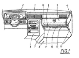
- Fig. 1 shows a perspective view of a vehicle passenger compartment provided with an airbag arrangement in accordance with the present invention.
- a dashboard 1 In the compartment a dashboard 1, a steering wheel 2 and a centre console 3 are provided in a conventional manner.
- a glove compartment 4 provided with an openable lid 5 is arranged on the passenger side of the compartment.
- the lid 5 has a rounded shape and can be opened by pivoting it about an axis which is defined by a hinge device 6 along the lower edge of the lid 5.
- the lid 5 transforms into a lower panel 7 of the dashboard 1.
- the lower panel 7 transforms in turn into the section of the vehicle body which forms the floor 8 of the vehicle.
- the dashboard 1 is preferably arranged so that the lid 5 is positioned directly in front of the position in which a passenger normally places his knees.
- the glove compartment 4, the lid 5 and the lower panel 7 extend in the sidewards direction from the centre console 3 to the edge of the dashboard 1 which is adjacent to the vehicle door (not shown) on the passenger side.
- An airbag 9 is arranged on the reverse side of the lower panel 7, preferably in a space arranged just below the lid 5 of the glove compartment 4. In the inactive condition of the airbag 9 (i.e. in its non-inflated condition), it has an elongated disposition which is essentially perpendicular to the longitudinal direction of the vehicle. Fig. 1 shows the airbag 9 in this condition.
- the airbag 9 is per se of conventional kind and is therefore not described in detail.
- An inflation device is arranged in connection with the airbag 9, which device is preferably in the form of a gas generator 10 which is adapted for inflating the airbag 9 should a collision occur.
- the gas generator 10 is connected to an acceleration sensor (not shown) which in a known manner is adapted to detect whether a particularly high retardation occurs. If this is the case, the acceleration sensor emits a signal to the gas generator 10, which in turn will be activated so as to inflate the airbag 9.
- the airbag 9 is mounted in an essentially elongated support bracket 11 which in turn is fixed in the vehicle on the reverse side of the dashboard 1, preferably behind the lower panel 7.
- the gas generator 10 is also mounted on the support bracket 11.
- the airbag 9 is arranged behind the lower panel 7 and is directed towards an opening 12 which faces the inside of the glove compartment 4.
- This opening 12 is covered by an elongated lid 13 which is pivotally mounted by means of hinges 14 in the lower edge of the lid 13.
- the airbag 9 during actuation will be inflated inside the glove compartment 4.
- the airbag 9 can be arranged in the bottom of the glove compartment 4
- Fig. 2 shows the device according to the preferred embodiment, the airbag 9 being in its activated, inflated condition.
- the airbag 9 essentially is of conventional type, it is adapted as regards the shape and sewing thereof to the space inside the glove compartment 4. Furthermore, the airbag 9 extends laterally in a direction which essentially corresponds to the width of the lower panel 7 (see also Fig. 1). In this manner, effective protection can be obtained.
- the lid 5 of the glove compartment 4 is arranged so that it constitutes a load-distributing element in the form of a surface which is arranged essentially directly in front of the legs of the occupant. In the event of a collision, the force acting upon the airbag 9 will initially be absorbed and distributed along the surface which is constituted by the lid 5. In this manner, the impact on the occupant can be reduced.
- this load-distributing element is formed by the lid 5 of the glove compartment 4.
- the lid 5 is thus positioned essentially directly in front of the knees and lower parts of the legs of the occupant, i.e. at the position which is exposed to a high impact in the event of a collision. In this manner, the "built-in" flexibility of the lid 5 of the glove compartment 4 can be used to even out the impact on the exposed body parts of the occupant.
- the lid 5 can be manufactured from a particularly selected material.
- the lid 5 can be manufactured from a layer of ABS plastic, metal sheet, aluminium sheet or similar material having a certain elasticity as regards impact absorption.
- the lid 5 can be manufactured from a sandwich design which can comprise several material layers (for example three or more) which can be arranged according to the type plastic/metal/plastic.
- the embodiment according to Figs. 1 and 2 is based on the fact that the airbag 9 cooperates with an impact-absorbing element which preferably is constituted by the lid 5 itself of the glove compartment 4. Should a collision occur, the legs of the occupant will be forced in the forwards direction and hit the lid 5, whereby the force from the occupant will be distributed via the lid 5 and further on to the airbag 9. If the lid 5 is designed with suitable dimensions and from suitable materials, the impact from the occupant's legs can be distributed by means of the lid 5 and the airbag 9.
- the airbag is designed with a plurality of ventilation holes (not shown) assuring that the pressure in the airbag 9 is released with an even flow when a force is applied to the lid 5, which in turn distributes the load along the airbag 9.
- the airbag according to the above-mentioned embodiment can be provided with means for controlling the expansion thereof.
- said means can be constituted by a tearable textile, i.e. a textile element which for example is sewn onto the base panel of the lid and the front side of the airbag.
- the tearable textile constitutes a resistance which controls the desired direction of the airbag.
- said means can be constituted by so-called trap bands which embrace the airbag at certain positions and which restrain it from further expansion above a certain limit.
- a third alternative are tearable seams, by means of which the airbag can be expanded in accordance with a desired progression.
- the invention is not limited to the above-mentioned embodiments shown in the drawings, but may be varied within the scope of the subsequent claims.
- different materials can be used for the load-distributing element, i.e. the lid 5.
- the energy-absorption of the airbag 9 can also be affected by means of, for example, ventilation holes or by means of the gas flow and the permeability of the airbag 9.
- the device according to the invention can use an existing acceleration sensor which can be provided in the vehicle for use together with a conventional airbag for the upper torso.
- the invention can be assigned to a separate acceleration sensor.
- the vehicle may also comprise a computer-based control unit which can be adapted for coordinating the timing during activation of the different airbags.
- the lid 13 can be designed in different ways, and can also be in the form of a curtain, for example of textile, which will be torn by the airbag during expansion thereof.
- the invention can also be arranged in connection with a sensor for detecting whether a passenger sits in the seat.
- the airbag according to the invention can be arranged so as be enabled to be inflated only in the case where somebody is sitting in the seat.
Landscapes
- Engineering & Computer Science (AREA)
- Mechanical Engineering (AREA)
- Air Bags (AREA)
Abstract
Claims (8)
- Dispositif de protection personnelle dans des véhicules, comprenant un sac gonflable (9) qui, à son état inactif, est placé dans un espace associé à un tableau de bord (1) du véhicule et, à son état actif, s'étend essentiellement devant les jambes et les genoux d'un occupant du véhicule, un capteur de détection d'une condition correspondant de façon générale à une collision, et un dispositif (10) de gonflage du sac gonflable (9) lorsque le capteur détecte l'existence de cette condition, caractérisé en ce que le dispositif comprend un élément (5) de distribution de charge qui est constitué par le couvercle (5) d'une boíte à gants (4) et qui est placé essentiellement entre le sac gonflable (9) et la position d'un occupant dans le véhicule, le sac gonflable (9) coopérant avec le couvercle (5) à l'état actif pour la répartition d'une charge provenant de l'occupant (20).
- Dispositif selon la revendication 1, caractérisé en ce que le sac gonflable (9), pendant le gonflage, se dilate en direction parallèle au tableau de bord (1) et s'étend essentiellement dans la direction longitudinale du véhicule.
- Dispositif selon la revendication 1, caractérisé en ce que le sac gonflable (9) est disposé en coopération avec un espace essentiellement fermé (4) et en association avec le tableau de bord (1), le sac gonflable étant gonflé à l'intérieur dudit espace (4) lorsqu'il est gonflé.
- Dispositif selon l'une quelconque des revendications précédentes, caractérisé en ce que le sac gonflable (9), lorsqu'il est activé, est destiné à être gonflé par l'intermédiaire d'une ouverture allongée (12) placée dans le tableau de bord (1) et essentiellement perpendiculaire à la direction longitudinale du véhicule.
- Dispositif selon la revendication 4, caractérisé en ce qu'il comporte un couvercle (13) qui, à l'état inactif du sac gonflable (9), recouvre l'ouverture (12) et peut pivoter sous l'action du sac gonflable (9).
- Dispositif selon la revendication 1, caractérisé en ce que le couvercle (5) de la boíte à gants comporte au moins deux couches d'un matériau de matière plastique et/ou de métal.
- Procédé de protection personnelle d'un véhicule comprenant un sac gonflable (9) qui, à son état inactif, est disposé en coopération avec un tableau de bord (1), comprenant :caractérisé en ce que le procédé comprend la commande de l'activation de manière que :la détection, par un capteur, d'une condition du véhicule qui correspond de façon générale à une collision, etl'activation du sac gonflable (9) lorsque ladite condition existe,le sac gonflable (9) se dilate d'une première position derrière le tableau de bord (1) à une seconde position essentiellement juste en avant les jambes et les genoux de l'occupant (20) du véhicule, et de manière queune charge agissant sur le sac gonflable (9) sous l'action de l'occupant soit absorbée et distribuée par un élément (5) de distribution de charge constitué par le couvercle (5) d'une boíte à gants (5) et qui se trouve essentiellement entre le sac gonflable (9) et la position de l'occupant (20).
- Procédé selon la revendication 7, caractérisé en ce que le sac gonflable (9), au cours de l'activation, est gonflé à l'intérieur d'un espace essentiellement fermé (4) en association avec le tableau de bord (1).
Priority Applications (1)
| Application Number | Priority Date | Filing Date | Title |
|---|---|---|---|
| EP01203452A EP1164061B1 (fr) | 1995-09-04 | 1996-09-04 | Dispositif et procédé pour la protection des occupants dans des véhicules |
Applications Claiming Priority (3)
| Application Number | Priority Date | Filing Date | Title |
|---|---|---|---|
| SE9503037A SE513029C2 (sv) | 1995-09-04 | 1995-09-04 | Anordning och förfarande för personskydd i fordon |
| SE9503037 | 1995-09-04 | ||
| PCT/SE1996/001092 WO1997009207A1 (fr) | 1995-09-04 | 1996-09-04 | Dispositif et procede de protection destine a un occupant d'un vehicule |
Related Child Applications (1)
| Application Number | Title | Priority Date | Filing Date |
|---|---|---|---|
| EP01203452A Division EP1164061B1 (fr) | 1995-09-04 | 1996-09-04 | Dispositif et procédé pour la protection des occupants dans des véhicules |
Publications (2)
| Publication Number | Publication Date |
|---|---|
| EP0848675A1 EP0848675A1 (fr) | 1998-06-24 |
| EP0848675B1 true EP0848675B1 (fr) | 2002-05-29 |
Family
ID=20399358
Family Applications (2)
| Application Number | Title | Priority Date | Filing Date |
|---|---|---|---|
| EP01203452A Expired - Lifetime EP1164061B1 (fr) | 1995-09-04 | 1996-09-04 | Dispositif et procédé pour la protection des occupants dans des véhicules |
| EP96930469A Expired - Lifetime EP0848675B1 (fr) | 1995-09-04 | 1996-09-04 | Dispositif et procede de protection destine a un occupant d'un vehicule |
Family Applications Before (1)
| Application Number | Title | Priority Date | Filing Date |
|---|---|---|---|
| EP01203452A Expired - Lifetime EP1164061B1 (fr) | 1995-09-04 | 1996-09-04 | Dispositif et procédé pour la protection des occupants dans des véhicules |
Country Status (6)
| Country | Link |
|---|---|
| US (1) | US6092836A (fr) |
| EP (2) | EP1164061B1 (fr) |
| JP (1) | JPH11512057A (fr) |
| DE (2) | DE69634388T8 (fr) |
| SE (1) | SE513029C2 (fr) |
| WO (1) | WO1997009207A1 (fr) |
Families Citing this family (49)
| Publication number | Priority date | Publication date | Assignee | Title |
|---|---|---|---|---|
| US20040256842A1 (en) * | 1994-05-23 | 2004-12-23 | Breed David S. | Knee bolster airbag system |
| DE29613045U1 (de) * | 1996-07-26 | 1996-11-21 | Trw Repa Gmbh | Knieschutzeinrichtung |
| DE19858520C5 (de) * | 1998-12-18 | 2004-03-04 | Autoliv Development Ab | Knieschutzeinrichtung mit Lastverteilkäfig |
| FR2789022B1 (fr) * | 1999-02-03 | 2001-04-06 | Allibert Ind | Equipement interieur de vehicule pour la protection d'un occupant en cas de choc |
| US6631920B1 (en) * | 1999-02-18 | 2003-10-14 | Delphi Technologies, Inc. | Airbag module |
| US6276713B1 (en) * | 2000-05-01 | 2001-08-21 | Textron Automotive Company Inc. | Passenger protection apparatus for a motor vehicle |
| JP4513834B2 (ja) * | 2000-07-07 | 2010-07-28 | 豊田合成株式会社 | 膝保護用エアバッグ装置 |
| EP2042383B1 (fr) | 2000-07-07 | 2011-05-11 | Toyoda Gosei Co., Ltd. | Dispositif d'airbag protégeant les genoux |
| AU2001269454A1 (en) * | 2000-07-07 | 2002-01-21 | Toyoda Gosei Co. Ltd. | Air bag device for knee protection |
| US7182365B2 (en) * | 2000-07-07 | 2007-02-27 | Toyoda Gosei Co., Ltd. | Air bag device for knee protection |
| FR2814413B1 (fr) | 2000-09-25 | 2003-02-28 | Ecia Equip Composants Ind Auto | Porte a sac gonflable integre, ensemble et module correspondant |
| US6464255B1 (en) * | 2001-05-10 | 2002-10-15 | Patent Holding Company | Knee bolster airbag system |
| JP4715030B2 (ja) * | 2001-05-21 | 2011-07-06 | タカタ株式会社 | 乗員脚部保護装置 |
| US6715789B2 (en) * | 2001-05-21 | 2004-04-06 | Toyoda Gosei Co., Ltd. | Knee protecting airbag device |
| US6945557B2 (en) * | 2001-11-09 | 2005-09-20 | Toyoda Gosei Co., Ltd. | Knee protecting airbag device |
| JP4626090B2 (ja) * | 2001-05-28 | 2011-02-02 | タカタ株式会社 | 乗員脚部保護装置 |
| JP4595246B2 (ja) * | 2001-05-28 | 2010-12-08 | Tkj株式会社 | 車両乗員保護装置 |
| US20050040630A1 (en) * | 2001-09-28 | 2005-02-24 | Trw Vehicle Safety Systems Inc. | Apparatus with specified relationship between an instrument panel and a deployment door |
| DE10151367B4 (de) * | 2001-10-17 | 2007-11-08 | Faurecia Innenraum Systeme Gmbh | Innenverkleidungsteil für Kraftfahrzeuge |
| US6536802B1 (en) * | 2001-11-13 | 2003-03-25 | Trw Vehicle Safety Systems Inc. | Vehicle instrument panel assembly |
| KR100482057B1 (ko) | 2001-12-19 | 2005-04-13 | 현대자동차주식회사 | 운전자의 무릎보호용 에어백장치 |
| DE10207885A1 (de) * | 2002-02-20 | 2003-09-04 | Takata Petri Ag | Airbaganordnung |
| KR20040015832A (ko) * | 2002-08-12 | 2004-02-21 | 현대모비스 주식회사 | 자동차의 사이드 에어백 |
| JP4120388B2 (ja) * | 2002-12-16 | 2008-07-16 | タカタ株式会社 | 乗員脚部保護装置を有する車両 |
| US7090245B2 (en) * | 2002-12-16 | 2006-08-15 | Takata Corporation | Leg protection system and vehicle having the same |
| US7175195B2 (en) * | 2002-12-25 | 2007-02-13 | Toyoda Gosei Co., Ltd. | Occupant protection device |
| US6971667B2 (en) * | 2003-01-14 | 2005-12-06 | Autoliv Asp, Inc. | Glove compartment airbag system |
| JP4016842B2 (ja) * | 2003-01-24 | 2007-12-05 | トヨタ自動車株式会社 | 車両用乗員膝部保護装置 |
| DE10318962A1 (de) * | 2003-04-26 | 2004-11-11 | Adam Opel Ag | Verkleidung für ein Airbaggehäuse eines Kraftfahrzeuges |
| US7261318B2 (en) * | 2003-12-01 | 2007-08-28 | Autoliv Asp, Inc. | Knee airbag and glove box assembly |
| US20050151351A1 (en) * | 2004-01-12 | 2005-07-14 | Enders Mark L. | Fabric knee airbag for high internal pressures |
| JP2005343180A (ja) * | 2004-05-31 | 2005-12-15 | Nippon Plast Co Ltd | エアバッグ装置 |
| DE202004018987U1 (de) * | 2004-12-02 | 2005-08-18 | Takata-Petri Ag | Gassack zum Schutz des Kniebereichs eines Fahrzeuginsassen |
| DE102005037845B4 (de) * | 2004-12-02 | 2010-04-01 | Takata-Petri Ag | Gassack zum Schutz des Kniebereichs eines Fahrzeuginsassen |
| JP4605000B2 (ja) * | 2005-12-14 | 2011-01-05 | トヨタ自動車株式会社 | 膝保護用エアバッグ装置 |
| US7452002B2 (en) * | 2006-03-27 | 2008-11-18 | Key Safety Systems, Inc. | Inflatable knee bolster airbag with internal tether |
| JP5151342B2 (ja) * | 2007-09-18 | 2013-02-27 | トヨタ自動車株式会社 | 車両用ニーエアバッグ装置 |
| US8235414B2 (en) * | 2007-11-30 | 2012-08-07 | Toyota Jidosha Kabushiki Kaisha | Glove door-installed knee air bag apparatus |
| US7641223B2 (en) * | 2007-12-07 | 2010-01-05 | Gm Global Technology Operations, Inc. | Knee airbag apparatus for a motorized vehicle |
| EP2072348B1 (fr) * | 2007-12-18 | 2016-10-05 | Autoliv Development AB | Coussin d'air pour genoux et son procédé de pliage |
| DE102008039552B4 (de) * | 2008-08-25 | 2017-02-16 | GM Global Technology Operations LLC (n. d. Ges. d. Staates Delaware) | Fahrzeuginnenverkleidung mit einer Airbagabdeckung |
| US7823952B2 (en) * | 2008-10-06 | 2010-11-02 | Korry Electronics Co. | Reconfigurable dashboard assembly for military vehicles |
| US8696019B2 (en) * | 2011-03-21 | 2014-04-15 | Tk Holdings Inc. | Knee airbag module |
| US8590928B2 (en) * | 2011-07-18 | 2013-11-26 | Ford Global Technologies, Llc | Knee airbag with passive venting for out of position occupant protection |
| US8596681B1 (en) | 2012-05-30 | 2013-12-03 | Nissan North America, Inc. | Internal deployable vehicle panel assembly |
| JP5891210B2 (ja) * | 2013-08-29 | 2016-03-22 | 富士重工業株式会社 | 乗員保護装置 |
| JP5816662B2 (ja) | 2013-08-29 | 2015-11-18 | 富士重工業株式会社 | 乗員保護装置 |
| JP6365335B2 (ja) | 2015-02-10 | 2018-08-01 | 株式会社デンソー | 暖房装置 |
| KR101694024B1 (ko) * | 2015-07-01 | 2017-01-06 | 현대자동차주식회사 | 차량의 무릎 보호 구조물 |
Family Cites Families (13)
| Publication number | Priority date | Publication date | Assignee | Title |
|---|---|---|---|---|
| US2834606A (en) * | 1955-10-05 | 1958-05-13 | Harry A Bertrand | Safety device for passengers |
| US3514124A (en) * | 1967-08-16 | 1970-05-26 | Eaton Yale & Towne | Vehicle safety device |
| US3642303A (en) * | 1970-02-13 | 1972-02-15 | Gen Motors Corp | Vehicle occupant restraint system |
| US3768830A (en) * | 1970-09-23 | 1973-10-30 | Eaton Corp | Vehicle knee bag |
| DE2634222A1 (de) * | 1976-07-30 | 1978-02-02 | Bayerische Motoren Werke Ag | Sicherheitseinrichtung in kraftfahrzeugen mit einem knieaufschlagelement |
| DE3029913C2 (de) * | 1980-08-07 | 1985-01-03 | Audi Nsu Auto Union Ag, 7107 Neckarsulm | Sicherheitseinrichtung für Fahrzeuge |
| GB2218385A (en) * | 1988-03-29 | 1989-11-15 | Trw Repa Gmbh | Vehicle passive restraint system with gas bag and knee cushion |
| DE4204280B4 (de) * | 1991-02-25 | 2007-01-18 | Volkswagen Ag | Airbagbestückter Seitenschutz für einen Kraftfahrzeuginsassen |
| DE4209604C2 (de) * | 1991-04-04 | 1996-12-12 | Volkswagen Ag | Behälterdeckel in einem Fahrzeugraum, insbesondere Handschuhfachdeckel |
| JPH05208646A (ja) * | 1992-01-31 | 1993-08-20 | Takata Kk | 車両乗員の保護装置 |
| JP3082392B2 (ja) * | 1992-02-05 | 2000-08-28 | タカタ株式会社 | 車両乗員の保護装置 |
| DE4227528C1 (de) * | 1992-08-20 | 1993-12-23 | Daimler Benz Ag | Anordnung eines aufblasbaren Beifahreraufprallschutzes |
| CA2145485C (fr) * | 1994-05-23 | 1999-01-05 | Autoliv Asp, Inc. | Panneau a la hauteur du genou fermant un compartiment pour sac de securite gonflable |
-
1995
- 1995-09-04 SE SE9503037A patent/SE513029C2/sv not_active IP Right Cessation
-
1996
- 1996-09-04 US US09/029,389 patent/US6092836A/en not_active Expired - Fee Related
- 1996-09-04 JP JP9511133A patent/JPH11512057A/ja not_active Ceased
- 1996-09-04 EP EP01203452A patent/EP1164061B1/fr not_active Expired - Lifetime
- 1996-09-04 DE DE69634388T patent/DE69634388T8/de active Active
- 1996-09-04 EP EP96930469A patent/EP0848675B1/fr not_active Expired - Lifetime
- 1996-09-04 DE DE69621442T patent/DE69621442T2/de not_active Expired - Lifetime
- 1996-09-04 WO PCT/SE1996/001092 patent/WO1997009207A1/fr not_active Ceased
Also Published As
| Publication number | Publication date |
|---|---|
| US6092836A (en) | 2000-07-25 |
| SE9503037L (sv) | 1997-03-05 |
| WO1997009207A1 (fr) | 1997-03-13 |
| SE9503037D0 (sv) | 1995-09-04 |
| DE69634388T2 (de) | 2006-01-12 |
| DE69621442D1 (de) | 2002-07-04 |
| DE69634388D1 (de) | 2005-03-31 |
| EP0848675A1 (fr) | 1998-06-24 |
| EP1164061B1 (fr) | 2005-02-23 |
| SE513029C2 (sv) | 2000-06-19 |
| EP1164061A1 (fr) | 2001-12-19 |
| JPH11512057A (ja) | 1999-10-19 |
| DE69621442T2 (de) | 2003-01-09 |
| DE69634388T8 (de) | 2006-04-27 |
Similar Documents
| Publication | Publication Date | Title |
|---|---|---|
| EP0848675B1 (fr) | Dispositif et procede de protection destine a un occupant d'un vehicule | |
| JP3082392B2 (ja) | 車両乗員の保護装置 | |
| EP0684164B1 (fr) | Dispositif de protection des genoux mis en place par sac gonflable | |
| US11458922B2 (en) | Floor-mounted occupant restraint system | |
| US5564736A (en) | Side airbag apparatus | |
| US6302437B1 (en) | Vehicle glove box assembly having knee restraint capabilities | |
| JP2922001B2 (ja) | 車体側部のエネルギ吸収構造 | |
| US6299209B1 (en) | Protective device for motor vehicle occupants | |
| GB2338688A (en) | Inflatable trim panel | |
| US20200391691A1 (en) | Seat-mounted occupant restraint system | |
| US5718449A (en) | Side-impact airbag device | |
| US20060125215A1 (en) | Airbag module | |
| US6164685A (en) | Deployment door for air bag module | |
| JP3713823B2 (ja) | 車両のサイドエアバッグ装置 | |
| US6340170B1 (en) | Actuatable knee bolster | |
| JPH04166452A (ja) | 乗員保護装置 | |
| JP2915380B2 (ja) | 車体側部のエネルギ吸収構造 | |
| JPH0312602Y2 (fr) | ||
| EP1031475A2 (fr) | Système de protection en cas de choc arrière | |
| JP2867131B2 (ja) | 車体側部のエネルギ吸収構造 | |
| KR100196187B1 (ko) | 조수석 에어백의 도어 장치 | |
| JP2938835B2 (ja) | 車体側部のエネルギ吸収構造 | |
| JP2975464B2 (ja) | 自動車の後部構造 | |
| KR20190071507A (ko) | 차량용 에어백장치 | |
| JPH05229395A (ja) | 乗員保護装置 |
Legal Events
| Date | Code | Title | Description |
|---|---|---|---|
| PUAI | Public reference made under article 153(3) epc to a published international application that has entered the european phase |
Free format text: ORIGINAL CODE: 0009012 |
|
| 17P | Request for examination filed |
Effective date: 19980223 |
|
| AK | Designated contracting states |
Kind code of ref document: A1 Designated state(s): DE FR GB |
|
| 17Q | First examination report despatched |
Effective date: 19990816 |
|
| GRAG | Despatch of communication of intention to grant |
Free format text: ORIGINAL CODE: EPIDOS AGRA |
|
| GRAG | Despatch of communication of intention to grant |
Free format text: ORIGINAL CODE: EPIDOS AGRA |
|
| GRAH | Despatch of communication of intention to grant a patent |
Free format text: ORIGINAL CODE: EPIDOS IGRA |
|
| GRAA | (expected) grant |
Free format text: ORIGINAL CODE: 0009210 |
|
| AK | Designated contracting states |
Kind code of ref document: B1 Designated state(s): DE FR GB |
|
| REG | Reference to a national code |
Ref country code: GB Ref legal event code: FG4D |
|
| REF | Corresponds to: |
Ref document number: 69621442 Country of ref document: DE Date of ref document: 20020704 |
|
| ET | Fr: translation filed | ||
| PLBE | No opposition filed within time limit |
Free format text: ORIGINAL CODE: 0009261 |
|
| STAA | Information on the status of an ep patent application or granted ep patent |
Free format text: STATUS: NO OPPOSITION FILED WITHIN TIME LIMIT |
|
| 26N | No opposition filed |
Effective date: 20030303 |
|
| PGFP | Annual fee paid to national office [announced via postgrant information from national office to epo] |
Ref country code: GB Payment date: 20090902 Year of fee payment: 14 |
|
| PGFP | Annual fee paid to national office [announced via postgrant information from national office to epo] |
Ref country code: DE Payment date: 20090827 Year of fee payment: 14 |
|
| PGFP | Annual fee paid to national office [announced via postgrant information from national office to epo] |
Ref country code: FR Payment date: 20091012 Year of fee payment: 14 |
|
| GBPC | Gb: european patent ceased through non-payment of renewal fee |
Effective date: 20100904 |
|
| REG | Reference to a national code |
Ref country code: FR Ref legal event code: ST Effective date: 20110531 |
|
| REG | Reference to a national code |
Ref country code: DE Ref legal event code: R119 Ref document number: 69621442 Country of ref document: DE Effective date: 20110401 |
|
| PG25 | Lapsed in a contracting state [announced via postgrant information from national office to epo] |
Ref country code: DE Free format text: LAPSE BECAUSE OF NON-PAYMENT OF DUE FEES Effective date: 20110401 Ref country code: FR Free format text: LAPSE BECAUSE OF NON-PAYMENT OF DUE FEES Effective date: 20100930 |
|
| PG25 | Lapsed in a contracting state [announced via postgrant information from national office to epo] |
Ref country code: GB Free format text: LAPSE BECAUSE OF NON-PAYMENT OF DUE FEES Effective date: 20100904 |