EP0848814B1 - Lumineszenz messvorrichtung, insbesondere zur medizinischen analyse - Google Patents
Lumineszenz messvorrichtung, insbesondere zur medizinischen analyse Download PDFInfo
- Publication number
- EP0848814B1 EP0848814B1 EP96930199A EP96930199A EP0848814B1 EP 0848814 B1 EP0848814 B1 EP 0848814B1 EP 96930199 A EP96930199 A EP 96930199A EP 96930199 A EP96930199 A EP 96930199A EP 0848814 B1 EP0848814 B1 EP 0848814B1
- Authority
- EP
- European Patent Office
- Prior art keywords
- axis
- sensor
- luminometer
- along
- moving
- Prior art date
- Legal status (The legal status is an assumption and is not a legal conclusion. Google has not performed a legal analysis and makes no representation as to the accuracy of the status listed.)
- Expired - Lifetime
Links
Images



Classifications
-
- G—PHYSICS
- G01—MEASURING; TESTING
- G01N—INVESTIGATING OR ANALYSING MATERIALS BY DETERMINING THEIR CHEMICAL OR PHYSICAL PROPERTIES
- G01N21/00—Investigating or analysing materials by the use of optical means, i.e. using sub-millimetre waves, infrared, visible or ultraviolet light
- G01N21/17—Systems in which incident light is modified in accordance with the properties of the material investigated
- G01N21/25—Colour; Spectral properties, i.e. comparison of effect of material on the light at two or more different wavelengths or wavelength bands
- G01N21/251—Colorimeters; Construction thereof
- G01N21/253—Colorimeters; Construction thereof for batch operation, i.e. multisample apparatus
-
- G—PHYSICS
- G01—MEASURING; TESTING
- G01N—INVESTIGATING OR ANALYSING MATERIALS BY DETERMINING THEIR CHEMICAL OR PHYSICAL PROPERTIES
- G01N21/00—Investigating or analysing materials by the use of optical means, i.e. using sub-millimetre waves, infrared, visible or ultraviolet light
- G01N21/75—Systems in which material is subjected to a chemical reaction, the progress or the result of the reaction being investigated
- G01N21/76—Chemiluminescence; Bioluminescence
Definitions
- the subject of the present invention is a luminometer intended more particularly to the rapid analysis of a very large number of samples of small volumes, particularly in the field of medical analyzes.
- the luminometer of the present invention also aims to be integrated in the moving head of a multi-function analysis device.
- This luminometer is also equipped with a fixed guide mask and occultation.
- This mask includes a central groove oriented along the Y axis, so as to guide the head which is pressed by the return means elastic against the mask and more particularly in the groove, when the head is moved along the Y axis.
- a sealing sleeve completes the connection between the head and the groove to avoid the penetration of parasitic photons.
- this prior art proposes to press the microtitration plate on the underside of the mask by interposing a little foam between the microtiter plate and the plate which supports it, which remains random on such a large surface area, not to mention that the recall power of a foam is difficult to control over its entire surface.
- the senor is far from the measurement location a distance equal to the length of the arm, a distance that can hardly be reduced since it must be able to access the entire surface of the microtitration plate, so provision is made for the interposition of a link by optical fiber.
- EP-A-181 060 describes a measuring head allowing sealing with the sample support plate.
- the sensor is also distant from the measuring head and especially the sample support plate is specific, which goes to against a certain standardization.
- This request presents a luminometer equipped with a table which carries the samples to be analyzed, movable along the X axis.
- a carriage carries a luminometry measuring cell.
- Means are used to press the measuring cell onto the samples. It is a shock absorber which allows mobility along the Z axis but without means for moving the cell along the Z axis.
- the damper uses a seal that slides over the surface of the sample wells and who works in shear, which is not satisfactory.
- friction can cause pollution from one well to another by entrainment of possible traces on the periphery of the wells.
- the object of the present invention is to overcome the drawbacks of the prior art luminometers by having a measurement sensor directly on a support movable at least in Z so that it comes to be pressed directly on reaction vessels such as the wells of a plate of microtiter or any other low volume container.
- This type of sensor developed and used in other applications, particularly for transmission by optical fibers, is resistant to vibrations, accelerations and micro-shocks generated by high-speed movements.
- His sensitivity is not necessarily as important as that of type sensors photomultiplier by reflection but it is compensated, of all ways, by the proximity of the sensor to the emission source, by the makes the link a transmission of an electrical signal and not more than a light signal since the signal is transformed in the sensor itself and also by the fact that, as in the prior art, one overcomes the disturbances caused by external photons or simply emitted by adjacent samples, known as cross contamination.
- the invention also relates to the integration of such a luminometer in the working head of a particular apparatus also ensuring the measurement of several parameters which have been the subject of a patent application in the name of the present applicant and bearing the number EP-A-92/450 011.
- This device very high performance, has a very high speed head of displacement leading to accelerations of the order of 2 g.
- the luminometer comprises a frame protected by a cover, the interior of which is accessible through a shutter closing, a photon measurement sensor with a measurement window, a support plate for sample plates, fixed or with means for move said plate in a system of orthogonal axes X, Y and Z, oriented preferably but not necessarily with the vertical Z axis, along at least one of the axes of the X or Y plane, an electronic module of amplification and digitization of data and an electronic module of processing of this data and this luminometer is characterized in that the measurement sensor is mobile and in that it comprises means for translational movement of this sensor at least along the axis of the Z.
- the chassis is equipped with means for translational movement only along one of the axes of the plane, the Y axis, and the sensor and the means of displacement in translation along the axis of the Z are carried by displacement means in translation along the other of the axes of the planes, the X axis.
- the means of displacement in Z comprise a carriage mounted sliding on a rail oriented along the Z axis and a motor with an integrated encoder integral with a frame, driving a rotating cam intended to ensure said displacement in translation, this frame being carried by a carriage mounted sliding on a rail, supported by a recessed beam one of its ends, oriented along the X axis, said carriage being driven by a set of a belt stretched between a roller and a pulley of a motor with integrated encoder.
- the electronic module of amplification and digitization of data is carried by the means of translational movement along the X axis and located nearby sensor immediately.
- the sensor includes a photomultiplier and an electronic module integrated measurement acquisition, the whole being protected by shielding.
- sealing means and to compensate for flatness defects at the level of the measurement window are added.
- the invention also relates to a measuring device comprising at minus a microtiter plate support, a movable head, equipped with means for measuring different physico-chemical parameters, means in displacement in translation of said head along the X and Y axes, this device comprising a luminometer integrated in the head equipped with only means of displacement in translation along the axis of Z.
- the displacement cam of the previous embodiment is replaced by a screw / nut assembly.
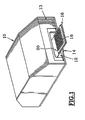
- FIG 1 there is shown in perspective a luminometer according to the invention, as presented to the user.
- This luminometer includes a cowling 10 on three of its faces and a cover 12 on the front face 13, closed by a tilting flap 14.
- a microtiter plate 16 comprising microwells 18, resting on a movable stage 20.
- the luminometer presents a overall length and width, each substantially equal to two times the dimensions, respectively in length and in width, of a plate analysis standard, which shows the compactness of such equipment, as will be confirmed by the details later given in the description.
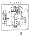
- the luminometer comprises a frame 22 comprising first means for translational movement 24, along the Y axis.
- first means 24 comprising, in the embodiment not limitative shown, a guide rail 26 on which is slidably mounted a carriage 28 (see Figure 3), integral with plate 20, plate support microtitration 16.
- Second means of displacement are also provided.
- These displacement means 38 comprise a rail 42 fixed on a beam 44 of great rigidity, secured to the chassis 22 by a foot 46 and a assembly of a belt 48, stretched between a roller 50 carried by a base 52 and the drive pulley 54 of a motor 56 with an encoder integrated.
- a carriage 58 is secured to the belt 48 by clamps 57 linked said carriage so as to move the latter on the rail 42 according to a translational movement in X in both directions with displacements perfectly controlled.
- the carriage 58 carries the frame 39 on which are reported third means for translational movement 60, along the axis of Z.
- These third means of translational movement 60 comprise a motor 62 with an integrated encoder, the output shaft 64 of which is fixed to a cam 66 which actuates a movable plate 68 on which the sensor 40.
- the plate 68 is integral with a carriage 70, slidably mounted on a rail 72 carried by the frame 39.
- the displacements along the Z axis are of small amplitude.
- the chassis is further equipped with a stop 74, equipped with a limit switch 76, making it possible to zero.
- the device is also equipped with means for calibration 78 schematically represented in the figure as a well 80 and a lamp 82.
- the well is indeed a simple blind housing on which comes to rest the sensor when returning to neutral position, so that said sensor is not disturbed by excess light from outside as will be described later in the description.
- the lamp is at contrary to a constant light source, protected from any disturbance outside, at the bottom of the well, which allows the sensor to be reset when this is necessary to compensate for any drifts.
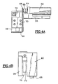
- Such a sensor is sold in particular by the company HAMAMATSU.
- This sensor has fast response time, measurement sensitivity sufficient, it is almost insensitive to magnetic disturbances and electromagnetic, even of high power, and above all it is insensitive to vibrations and accelerations generated by displacements mechanical.
- the luminometer is completed by an electronic set of information processing with memory, not shown, only the module signal 96 amplification is symbolized by a dashed line in Figure 2, because this module for reasons of gain of sensitivity is embedded and carried by the carriage 58. In fact, cable connections must be reduced as much as possible between the sensor and this amplifier, the digital output signal of this module can be transported without problem.
- the user wishing to carry out luminometry measurements on biological media first prepare its microtiter plate with the microwells in which it has the products to be studied.
- the measurements are then launched in a preprogrammed order which does not directly interest the invention.
- the displacements of a microwells to another are always the same.
- Motors 36 and 56 are powered and controlled by encoders to position the sensor at right of a given microwell. As soon as the sensor is in line with this microwell, the motor 62 is powered to lower the sensor 40 along the Z axis. The amplitude of the movement is known and the deviations are compensated by the washers 92 and 94.
- the window 87 of the sensor is centered on the microwells and any contamination by photons emitted by microwells adjacent is deleted.
- the motor 62 allows, if necessary, individualized treatment adapted to each well and the possible use of various plates and wells as well as a control of the presence of wells.
- the measurement is carried out and the acquired results are processed and transferred in the associated memory for paper output and / or subsequent analysis.
- the time interval between two measures is of the order of a second, to give an idea.
- the sensor is brought back to the right of the stop 78 and lowered to be pressed on the garage well 80.
- a drift control can be achieved by initializing the sensor. Just turn on the lamp and measure the photons emitted, the quantity of which is perfectly known.
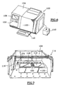
- FIG 6 there is shown a measuring device described in the European patent application EP-A-92/450 011, device in which is integrated the luminometer according to the invention, so as to increase its capacities.
- This device includes a cover 100 protecting the area of measurement 102 proper, an integrated electronic module 104 with a display screen 106 and a memory unit with a reader floppy disk 108, a waste container 110 and a keyboard command 112.
- the measurement area 102 includes an X-Y table 114 allowing the displacement of a measuring head 116 carrying the various instruments sampling and analysis.
- the actual head 116 has been shown which includes a front face 126 with a transparent casing 128 and a rear face 130 in which, according to the embodiment chosen, the housing and the luminometer according to the invention.
- the means 260 for translational movement along the Z axis comprising a base 239 supporting a rail 272 oriented vertically and secured to the frame 222 of the head.
- a carriage 258 is mounted movable in translation on said rail and further comprises a screw-nut assembly 259, the screw being driven by a motor 262 secured to chassis 222.
- the carriage carries, as before, a sensor 240.
- Signal amplification module 296 is located nearby sensor, directly on the frame 222 of the head and the assembly of connections is referenced 297.
- the type of sensor used can support accelerations of 2 g to which the head is subjected. These significant accelerations are due to fact that there is room in the measuring device of figure 6 for have a powerful X-Y table in order to move a relatively large distance with very short durations and we can notice that in this case the X-Y movements are combined, which leads to curvilinear movements of the head.
- direct measurement is a particularly attractive advantage for biological analyzes, in particular hormonal tests.
- the spectrophotometry varies from 1 to 3,000 and luminometry from 1 to 500,000.
- the senor indicated for carrying out the mode preferential can be replaced by any sensor whose integration and design allow to overcome vibrations while having a sufficient measurement sensitivity with good resistance to interference external of magnetic or electromagnetic origin, allowing its integration and its functioning in an industrial environment.
Landscapes
- Physics & Mathematics (AREA)
- Chemical & Material Sciences (AREA)
- General Physics & Mathematics (AREA)
- Immunology (AREA)
- Health & Medical Sciences (AREA)
- Analytical Chemistry (AREA)
- Biochemistry (AREA)
- General Health & Medical Sciences (AREA)
- Pathology (AREA)
- Life Sciences & Earth Sciences (AREA)
- Spectroscopy & Molecular Physics (AREA)
- Engineering & Computer Science (AREA)
- Chemical Kinetics & Catalysis (AREA)
- Plasma & Fusion (AREA)
- Investigating Or Analysing Materials By Optical Means (AREA)
- Investigating Or Analysing Materials By The Use Of Chemical Reactions (AREA)
- Investigating, Analyzing Materials By Fluorescence Or Luminescence (AREA)
- Acyclic And Carbocyclic Compounds In Medicinal Compositions (AREA)
Claims (9)
- Luminometer, das einen Rahmen (22), der durch eine Verkleidung (10) geschützt ist, deren Innenraum durch eine Verschlußklappe (14) zugänglich ist, einen Photonenmeßsensor (40) mit einem Meßfenster (87), eine Probenplatten-Trägerplatine (20), die fixiert ist oder mit Mitteln (24, 38) versehen ist, um die Platine in einem System aus orthogonalen Achsen X, Y und Z, das vorzugsweise, jedoch nicht notwendig, mit vertikaler Z-Achse orientiert ist, wenigstens längs einer der Achsen der XY-Ebene zu verlagern, ein elektronisches Modul (96) für die Verstärkung und die Digitalisierung der Daten und ein elektronisches Modul für die Verarbeitung dieser Daten umfaßt, dadurch gekennzeichnet, daß der Meßsensor (40) beweglich ist und daß das Luminometer Mittel (60) für die translatorische Verlagerung dieses Sensors wenigstens längs der Z-Achse umfaßt.
- Luminometer nach Anspruch 1, dadurch gekennzeichnet, daß der Rahmen (22) mit Mitteln (24) zur translatorischen Verlagerung ausschließlich längs einer der Achsen der Ebene, der Y-Achse, versehen ist und daß der Sensor (40) und die Mittel (60) zur translatorischen Verlagerung längs der Z-Achse durch Mittel (38) zur translatorischen Verlagerung längs der anderen der Achsen der Ebene, der X-Achse, getragen werden.
- Luminometer nach Anspruch 2, dadurch gekennzeichnet, daß die Z-Verlagerungsmittel (60) einen Schlitten (70), der an einer längs der Z-Achse orientierten Schiene (72) gleitend angebracht ist, sowie einen Motor (62) umfassen, der einen mit einem Gestell (39) fest verbundenen integrierten Codierer aufweist, der einen Nocken (66) rotatorisch antreibt, der dazu vorgesehen ist, die translatorische Verlagerung sicherzustellen, wobei dieses Gestell (39) von einem Schlitten (58) getragen wird, der an einer Schiene (42) gleitend angebracht ist, die durch einen Träger (44) unterstützt ist, der an einem seiner Enden eingespannt ist und längs der X-Achse orientiert ist, wobei der Schlitten (58) durch eine Baueinheit aus einem Riemen (48) angetrieben wird, der zwischen einer Rolle (50) und einer Scheibe (54) eines Motors (56) mit integriertem Codierer gespannt ist.
- Luminometer nach Anspruch 2 oder 3, dadurch gekennzeichnet, daß es an einem der Enden einen Anschlag (74) für die Verlagerung in X-Richtung umfaßt, der versehen ist mit einem Bahnende-Sensor (76), der eine Initialisierung der Verlagerungen ermöglicht, mit einem schwarzen Behälter (80), der ermöglicht, den Sensor (40) geschützt vor parasitären Störungen unterzubringen, und mit einer Kalibrierungslampe (82), die in dem schwarzen Behälter angeordnet ist und bei Bedarf eine Eichung des Sensors ermöglicht.
- Luminometer nach einem der Ansprüche 2, 3 oder 4, dadurch gekennzeichnet, daß das elektronische Modul (96) zur Verstärkung und Digitalisierung von Daten durch die Mittel (42, 58) zur translatorischen Verlagerung längs der X-Achse getragen wird und in unmittelbarer Nähe des Sensors angeordnet ist
- Luminometer nach einem der vorhergehenden Ansprüche, dadurch gekennzeichnet, daß der Sensor (40) einen Photovervielfacher (86) und ein integriertes elektronisches Modul (88) zur Erfassung von Meßwerten umfaßt, wobei die Gesamtheit durch eine Abschirmung (90) geschützt ist.
- Luminometer nach einem der vorhergehenden Ansprüche, dadurch gekennzeichnet, daß es Mittel (92, 94) zur Abdichtung und zur Kompensation von Ebenheitsfehlern am Ort des Meßfensters umfaßt.
- Meßvorrichtung, die wenigstens einen Mikrotitrationsplatten-Träger (118), einen beweglichen Kopf (116), der mit Mitteln zum Messen verschiedener physikalisch-chemischer Parameter versehen ist, und Mittel (114) zur translatorischen Verlagerung des Kopfes längs der X- und Y-Achsen umfaßt, dadurch gekennzeichnet, daß sie ein in den Kopf integriertes Luminometer (240, 259) nach einem der vorhergehenden Ansprüche umfaßt, das mit den einzigen Mitteln (260) zur translatorischen Verlagerung längs der Z-Achse versehen ist.
- Vorrichtung nach Anspruch 8, dadurch gekennzeichnet, daß die Z-Verlagerung durch Mittel (259) zur translatorischen Verlagerung des Schrauben/Mutter-Typs erhalten wird.
Applications Claiming Priority (3)
| Application Number | Priority Date | Filing Date | Title |
|---|---|---|---|
| FR9510503A FR2738344B1 (fr) | 1995-09-04 | 1995-09-04 | Luminometre notamment pour analyses medicales |
| FR9510503 | 1995-09-04 | ||
| PCT/FR1996/001344 WO1997009610A1 (fr) | 1995-09-04 | 1996-09-03 | Luminometre notamment pour analyses medicales |
Publications (2)
| Publication Number | Publication Date |
|---|---|
| EP0848814A1 EP0848814A1 (de) | 1998-06-24 |
| EP0848814B1 true EP0848814B1 (de) | 2003-12-03 |
Family
ID=9482358
Family Applications (1)
| Application Number | Title | Priority Date | Filing Date |
|---|---|---|---|
| EP96930199A Expired - Lifetime EP0848814B1 (de) | 1995-09-04 | 1996-09-03 | Lumineszenz messvorrichtung, insbesondere zur medizinischen analyse |
Country Status (6)
| Country | Link |
|---|---|
| US (1) | US6377342B1 (de) |
| EP (1) | EP0848814B1 (de) |
| AT (1) | ATE255722T1 (de) |
| DE (1) | DE69630961D1 (de) |
| FR (1) | FR2738344B1 (de) |
| WO (1) | WO1997009610A1 (de) |
Families Citing this family (24)
| Publication number | Priority date | Publication date | Assignee | Title |
|---|---|---|---|---|
| ES2322859T3 (es) | 1998-05-01 | 2009-06-30 | Gen-Probe Incorporated | Analizador de diagnostico automatizado. |
| US8337753B2 (en) | 1998-05-01 | 2012-12-25 | Gen-Probe Incorporated | Temperature-controlled incubator having a receptacle mixing mechanism |
| US20050279949A1 (en) * | 1999-05-17 | 2005-12-22 | Applera Corporation | Temperature control for light-emitting diode stabilization |
| US7423750B2 (en) * | 2001-11-29 | 2008-09-09 | Applera Corporation | Configurations, systems, and methods for optical scanning with at least one first relative angular motion and at least one second angular motion or at least one linear motion |
| GB0114294D0 (en) * | 2001-06-12 | 2001-08-01 | Techne Cambridge Ltd | Assay Apparatus |
| US20040087010A1 (en) * | 2002-11-04 | 2004-05-06 | Chung-Hua Tsai | Micro ELISA reader |
| EP1441216A3 (de) * | 2003-01-21 | 2005-07-20 | Tecan Trading AG | Vorrichtung und Verfahren zum Beobachten von Reaktionen in Proben |
| JP4381122B2 (ja) * | 2003-02-14 | 2009-12-09 | 晶宇生物科技實業股▲分▼有限公司 | 側壁付微細アレイバイオチップ反射型画像アクセス及び分析装置、並びにその方法 |
| USD515707S1 (en) * | 2003-09-01 | 2006-02-21 | Matsushita Electric Industrial Co., Ltd. | Fluorescent reader |
| US7555334B2 (en) * | 2003-10-20 | 2009-06-30 | Xenogen Corporation | Small animal light intensity monitor |
| USD515220S1 (en) * | 2004-04-13 | 2006-02-14 | Bioveris Corporation | Detection apparatus |
| CA2842402C (en) | 2005-03-10 | 2016-02-23 | Gen-Probe Incorporated | Systems and methods to perform assays for detecting or quantifying analytes within samples |
| DE102005036763B4 (de) * | 2005-08-04 | 2007-07-26 | Inheco Industrial Heating And Cooling Gmbh | System aus mehreren Inkubatoren |
| JP2007046904A (ja) * | 2005-08-05 | 2007-02-22 | Sanyo Electric Co Ltd | 反応検出装置 |
| CN101563594B (zh) * | 2006-08-02 | 2012-07-04 | 阿瓦尼斯实验室科技公司 | 光度计和操作方法 |
| FI20095217A0 (fi) * | 2009-03-05 | 2009-03-05 | Wallac Oy | Kuljetussuojauksella varustettu optinen mittausinstrumentti |
| US9046507B2 (en) | 2010-07-29 | 2015-06-02 | Gen-Probe Incorporated | Method, system and apparatus for incorporating capacitive proximity sensing in an automated fluid transfer procedure |
| AU2012222178B2 (en) | 2011-02-24 | 2014-12-18 | Gen-Probe Incorporated | Systems and methods for distinguishing optical signals of different modulation frequencies in an optical signal detector |
| CN107831324B (zh) | 2013-03-15 | 2021-11-19 | 雅培制药有限公司 | 具有后面可进入轨道系统的自动化诊断分析仪及相关方法 |
| JP6165961B2 (ja) | 2013-03-15 | 2017-07-19 | アボット・ラボラトリーズAbbott Laboratories | 前処理カルーセルを有する診断分析装置および関連方法 |
| ES3037815T3 (en) | 2013-03-15 | 2025-10-07 | Abbott Lab | Automated diagnostic analyzers having vertically arranged carousels and related methods |
| JP1720814S (ja) * | 2022-02-28 | 2022-07-27 | 生化学分析機 | |
| USD1021129S1 (en) * | 2022-10-28 | 2024-04-02 | Ruben Oganesyan | Organ chamber |
| CN118032301A (zh) * | 2024-02-22 | 2024-05-14 | 广东熠日照明科技有限公司 | 一种自动化测量光通量和光的均匀性的方法 |
Family Cites Families (7)
| Publication number | Priority date | Publication date | Assignee | Title |
|---|---|---|---|---|
| US4772453A (en) * | 1985-03-01 | 1988-09-20 | Lisenbee Wayne F | Luminiscence measurement arrangement |
| US5063024A (en) * | 1985-10-07 | 1991-11-05 | Labsystems Oy | Method and apparatus for immunological determinations |
| KR970003276B1 (ko) * | 1987-04-09 | 1997-03-17 | 가부시끼가이샤 메이덴샤 | 정량 분석 장치 |
| US5082628A (en) * | 1989-09-19 | 1992-01-21 | Park Pharmaceuticals, Inc. | Luminometer |
| DE4123817C2 (de) * | 1991-07-18 | 1994-06-09 | Berthold Lab Prof Dr | Strahlungsmeßgerät, insbesondere zur Messung der Lumineszenz |
| US5401465A (en) * | 1992-05-05 | 1995-03-28 | Chiron Corporation | Luminometer with reduced sample crosstalk |
| AU7802594A (en) * | 1993-10-18 | 1995-05-08 | Anthos Labtec Instruments Ges.M.B.H. | Luminometer |
-
1995
- 1995-09-04 FR FR9510503A patent/FR2738344B1/fr not_active Expired - Fee Related
-
1996
- 1996-09-03 DE DE69630961T patent/DE69630961D1/de not_active Expired - Lifetime
- 1996-09-03 EP EP96930199A patent/EP0848814B1/de not_active Expired - Lifetime
- 1996-09-03 AT AT96930199T patent/ATE255722T1/de not_active IP Right Cessation
- 1996-09-03 US US09/029,632 patent/US6377342B1/en not_active Expired - Fee Related
- 1996-09-03 WO PCT/FR1996/001344 patent/WO1997009610A1/fr not_active Ceased
Also Published As
| Publication number | Publication date |
|---|---|
| FR2738344B1 (fr) | 1997-11-21 |
| WO1997009610A1 (fr) | 1997-03-13 |
| ATE255722T1 (de) | 2003-12-15 |
| EP0848814A1 (de) | 1998-06-24 |
| US6377342B1 (en) | 2002-04-23 |
| DE69630961D1 (de) | 2004-01-15 |
| FR2738344A1 (fr) | 1997-03-07 |
Similar Documents
| Publication | Publication Date | Title |
|---|---|---|
| EP0848814A1 (de) | Lumineszenz massvorrichtung,insbesondere zur medizinischen analyse | |
| CN100565193C (zh) | 用于检测透明基片中的缺陷的检测装置 | |
| FR2721395A1 (fr) | Procédé de repérage positionnel d'un trièdre dans l'espace et dispositif pour la mise en Óoeuvre de ce procédé. | |
| WO2004046307A3 (en) | Scanning of biological samples | |
| CA2474073C (fr) | Dispositif pour l'analyse automatisee d'un echantillon liquide | |
| CH423278A (fr) | Dispositif pour déterminer les coordonnées relatives de deux ou plusieurs points sur un objet par rapport à deux axes qui se coupent | |
| JPH07506433A (ja) | サンプル間のクロストークを減少させるルミノメータ | |
| US4067694A (en) | Loading and unloading mechanism for continuously rotating container | |
| JPH04294252A (ja) | ディスク・ファイル並びに汚染物検知及び測定方法。 | |
| EP3973259B1 (de) | Infrarotlicht-ausstrahlende und -kontrollierende vorrichtung und gassensor mit einer solchen vorrichtung | |
| WO2013060945A1 (fr) | Dispositif d'inspection de plaquettes semi - conductrices a champ sombre. | |
| FR2485189A1 (fr) | Spectroscope optique a reseaux et miroirs pour microscope electronique a balyage | |
| WO2000031962A1 (fr) | Appareil d'acquisition d'images par fluorescence et systeme d'imagerie comportant un tel appareil | |
| FR2817350A1 (fr) | Appareil automatique de dosage immunologique | |
| FR2656688A1 (fr) | Dispositif de mesure du niveau d'un liquide dans un reservoir par determination optique de la position d'un flotteur. | |
| FR2771501A1 (fr) | Dispositif et procede de reconnaissance et de differenciation de supports formant cases dans des cassettes et d'objets en forme de disques, depose sur ceux-ci | |
| JP2000227414A (ja) | マイクロチップ電気泳動用のチップユニット | |
| NL9100248A (nl) | Inrichting voor het meten van de reflectie en/of transmissie van een voorwerp. | |
| FR2652416A3 (fr) | Appareil destine a la mesure de la vitesse de sedimentation des hematies. | |
| EP4407300B1 (de) | Kompakter gassensor mit einfachem design | |
| KR101802462B1 (ko) | 각도의존성 광발광 측정장치 | |
| CN218382370U (zh) | 光谱仪 | |
| CN119574515B (zh) | 基于激光诱导荧光光谱法的实验室尺度原位检测装置 | |
| FR2535451A1 (fr) | Appareil de mesure par triangulation optique pour determiner la position et relever le profil d'un objet | |
| EP2972225A1 (de) | Vorrichtung zur phasenanalyse von mehrphasengemischen |
Legal Events
| Date | Code | Title | Description |
|---|---|---|---|
| PUAI | Public reference made under article 153(3) epc to a published international application that has entered the european phase |
Free format text: ORIGINAL CODE: 0009012 |
|
| 17P | Request for examination filed |
Effective date: 19980303 |
|
| AK | Designated contracting states |
Kind code of ref document: A1 Designated state(s): AT BE CH DE DK ES FR GB GR IE IT LI LU NL PT SE |
|
| 17Q | First examination report despatched |
Effective date: 20000120 |
|
| GRAG | Despatch of communication of intention to grant |
Free format text: ORIGINAL CODE: EPIDOS AGRA |
|
| RAP1 | Party data changed (applicant data changed or rights of an application transferred) |
Owner name: SFRI DIAGNOSTICS |
|
| GRAG | Despatch of communication of intention to grant |
Free format text: ORIGINAL CODE: EPIDOS AGRA |
|
| GRAH | Despatch of communication of intention to grant a patent |
Free format text: ORIGINAL CODE: EPIDOS IGRA |
|
| GRAH | Despatch of communication of intention to grant a patent |
Free format text: ORIGINAL CODE: EPIDOS IGRA |
|
| GRAA | (expected) grant |
Free format text: ORIGINAL CODE: 0009210 |
|
| AK | Designated contracting states |
Kind code of ref document: B1 Designated state(s): AT BE CH DE DK ES FR GB GR IE IT LI LU NL PT SE |
|
| PG25 | Lapsed in a contracting state [announced via postgrant information from national office to epo] |
Ref country code: NL Free format text: LAPSE BECAUSE OF FAILURE TO SUBMIT A TRANSLATION OF THE DESCRIPTION OR TO PAY THE FEE WITHIN THE PRESCRIBED TIME-LIMIT Effective date: 20031203 Ref country code: IT Free format text: LAPSE BECAUSE OF FAILURE TO SUBMIT A TRANSLATION OF THE DESCRIPTION OR TO PAY THE FEE WITHIN THE PRESCRIBED TIME-LIMIT;WARNING: LAPSES OF ITALIAN PATENTS WITH EFFECTIVE DATE BEFORE 2007 MAY HAVE OCCURRED AT ANY TIME BEFORE 2007. THE CORRECT EFFECTIVE DATE MAY BE DIFFERENT FROM THE ONE RECORDED. Effective date: 20031203 Ref country code: IE Free format text: LAPSE BECAUSE OF FAILURE TO SUBMIT A TRANSLATION OF THE DESCRIPTION OR TO PAY THE FEE WITHIN THE PRESCRIBED TIME-LIMIT Effective date: 20031203 Ref country code: GB Free format text: LAPSE BECAUSE OF FAILURE TO SUBMIT A TRANSLATION OF THE DESCRIPTION OR TO PAY THE FEE WITHIN THE PRESCRIBED TIME-LIMIT Effective date: 20031203 Ref country code: AT Free format text: LAPSE BECAUSE OF FAILURE TO SUBMIT A TRANSLATION OF THE DESCRIPTION OR TO PAY THE FEE WITHIN THE PRESCRIBED TIME-LIMIT Effective date: 20031203 |
|
| REG | Reference to a national code |
Ref country code: GB Ref legal event code: FG4D Free format text: NOT ENGLISH |
|
| REG | Reference to a national code |
Ref country code: CH Ref legal event code: EP |
|
| REG | Reference to a national code |
Ref country code: IE Ref legal event code: FG4D Free format text: FRENCH |
|
| REF | Corresponds to: |
Ref document number: 69630961 Country of ref document: DE Date of ref document: 20040115 Kind code of ref document: P |
|
| PG25 | Lapsed in a contracting state [announced via postgrant information from national office to epo] |
Ref country code: SE Free format text: LAPSE BECAUSE OF FAILURE TO SUBMIT A TRANSLATION OF THE DESCRIPTION OR TO PAY THE FEE WITHIN THE PRESCRIBED TIME-LIMIT Effective date: 20040303 Ref country code: GR Free format text: LAPSE BECAUSE OF FAILURE TO SUBMIT A TRANSLATION OF THE DESCRIPTION OR TO PAY THE FEE WITHIN THE PRESCRIBED TIME-LIMIT Effective date: 20040303 Ref country code: DK Free format text: LAPSE BECAUSE OF FAILURE TO SUBMIT A TRANSLATION OF THE DESCRIPTION OR TO PAY THE FEE WITHIN THE PRESCRIBED TIME-LIMIT Effective date: 20040303 |
|
| PG25 | Lapsed in a contracting state [announced via postgrant information from national office to epo] |
Ref country code: DE Free format text: LAPSE BECAUSE OF FAILURE TO SUBMIT A TRANSLATION OF THE DESCRIPTION OR TO PAY THE FEE WITHIN THE PRESCRIBED TIME-LIMIT Effective date: 20040304 |
|
| PG25 | Lapsed in a contracting state [announced via postgrant information from national office to epo] |
Ref country code: ES Free format text: LAPSE BECAUSE OF FAILURE TO SUBMIT A TRANSLATION OF THE DESCRIPTION OR TO PAY THE FEE WITHIN THE PRESCRIBED TIME-LIMIT Effective date: 20040314 |
|
| NLV1 | Nl: lapsed or annulled due to failure to fulfill the requirements of art. 29p and 29m of the patents act | ||
| GBV | Gb: ep patent (uk) treated as always having been void in accordance with gb section 77(7)/1977 [no translation filed] |
Effective date: 20031203 |
|
| REG | Reference to a national code |
Ref country code: IE Ref legal event code: FD4D |
|
| PG25 | Lapsed in a contracting state [announced via postgrant information from national office to epo] |
Ref country code: LU Free format text: LAPSE BECAUSE OF NON-PAYMENT OF DUE FEES Effective date: 20040903 |
|
| PG25 | Lapsed in a contracting state [announced via postgrant information from national office to epo] |
Ref country code: LI Free format text: LAPSE BECAUSE OF NON-PAYMENT OF DUE FEES Effective date: 20040930 Ref country code: CH Free format text: LAPSE BECAUSE OF NON-PAYMENT OF DUE FEES Effective date: 20040930 Ref country code: BE Free format text: LAPSE BECAUSE OF NON-PAYMENT OF DUE FEES Effective date: 20040930 |
|
| PLBE | No opposition filed within time limit |
Free format text: ORIGINAL CODE: 0009261 |
|
| STAA | Information on the status of an ep patent application or granted ep patent |
Free format text: STATUS: NO OPPOSITION FILED WITHIN TIME LIMIT |
|
| 26N | No opposition filed |
Effective date: 20040906 |
|
| BERE | Be: lapsed |
Owner name: *SFRI DIAGNOSTICS Effective date: 20040930 |
|
| REG | Reference to a national code |
Ref country code: CH Ref legal event code: PL |
|
| PG25 | Lapsed in a contracting state [announced via postgrant information from national office to epo] |
Ref country code: FR Free format text: LAPSE BECAUSE OF NON-PAYMENT OF DUE FEES Effective date: 20050531 |
|
| REG | Reference to a national code |
Ref country code: FR Ref legal event code: ST |
|
| BERE | Be: lapsed |
Owner name: *SFRI DIAGNOSTICS Effective date: 20040930 |
|
| PG25 | Lapsed in a contracting state [announced via postgrant information from national office to epo] |
Ref country code: PT Free format text: LAPSE BECAUSE OF NON-PAYMENT OF DUE FEES Effective date: 20040503 |