EP0848935B1 - Seringue - Google Patents
Seringue Download PDFInfo
- Publication number
- EP0848935B1 EP0848935B1 EP97118900A EP97118900A EP0848935B1 EP 0848935 B1 EP0848935 B1 EP 0848935B1 EP 97118900 A EP97118900 A EP 97118900A EP 97118900 A EP97118900 A EP 97118900A EP 0848935 B1 EP0848935 B1 EP 0848935B1
- Authority
- EP
- European Patent Office
- Prior art keywords
- syringe
- ejector
- piston
- nozzle
- ejector body
- Prior art date
- Legal status (The legal status is an assumption and is not a legal conclusion. Google has not performed a legal analysis and makes no representation as to the accuracy of the status listed.)
- Expired - Lifetime
Links
Images
Classifications
-
- B—PERFORMING OPERATIONS; TRANSPORTING
- B05—SPRAYING OR ATOMISING IN GENERAL; APPLYING FLUENT MATERIALS TO SURFACES, IN GENERAL
- B05C—APPARATUS FOR APPLYING FLUENT MATERIALS TO SURFACES, IN GENERAL
- B05C17/00—Hand tools or apparatus using hand held tools, for applying liquids or other fluent materials to, for spreading applied liquids or other fluent materials on, or for partially removing applied liquids or other fluent materials from, surfaces
- B05C17/005—Hand tools or apparatus using hand held tools, for applying liquids or other fluent materials to, for spreading applied liquids or other fluent materials on, or for partially removing applied liquids or other fluent materials from, surfaces for discharging material from a reservoir or container located in or on the hand tool through an outlet orifice by pressure without using surface contacting members like pads or brushes
- B05C17/00503—Details of the outlet element
- B05C17/00516—Shape or geometry of the outlet orifice or the outlet element
-
- A—HUMAN NECESSITIES
- A61—MEDICAL OR VETERINARY SCIENCE; HYGIENE
- A61C—DENTISTRY; APPARATUS OR METHODS FOR ORAL OR DENTAL HYGIENE
- A61C5/00—Filling or capping teeth
- A61C5/60—Devices specially adapted for pressing or mixing capping or filling materials, e.g. amalgam presses
- A61C5/66—Capsules for filling material
-
- B—PERFORMING OPERATIONS; TRANSPORTING
- B05—SPRAYING OR ATOMISING IN GENERAL; APPLYING FLUENT MATERIALS TO SURFACES, IN GENERAL
- B05C—APPARATUS FOR APPLYING FLUENT MATERIALS TO SURFACES, IN GENERAL
- B05C17/00—Hand tools or apparatus using hand held tools, for applying liquids or other fluent materials to, for spreading applied liquids or other fluent materials on, or for partially removing applied liquids or other fluent materials from, surfaces
- B05C17/005—Hand tools or apparatus using hand held tools, for applying liquids or other fluent materials to, for spreading applied liquids or other fluent materials on, or for partially removing applied liquids or other fluent materials from, surfaces for discharging material from a reservoir or container located in or on the hand tool through an outlet orifice by pressure without using surface contacting members like pads or brushes
- B05C17/00576—Hand tools or apparatus using hand held tools, for applying liquids or other fluent materials to, for spreading applied liquids or other fluent materials on, or for partially removing applied liquids or other fluent materials from, surfaces for discharging material from a reservoir or container located in or on the hand tool through an outlet orifice by pressure without using surface contacting members like pads or brushes characterised by the construction of a piston as pressure exerting means, or of the co-operating container
Definitions
- the invention relates to a syringe for viscous compositions, according to the preamble of claim 1, and a method for manufacturing a syringe according to the preamble of claim 18.
- Such a syringe is known, for example, from US Pat. No. 3,900,954.
- This syringe is characterized by a particularly good one Utilization of the dental materials used.
- This is a Expulsion body provided at the front end of the plunger of the syringe, which has a tapered tip that should penetrate into an expulsion nozzle and there the dental mass should drive out as completely as possible.
- the expulsion body of this type can be used in the Reduce the syringe or dental mass remaining in the expulsion nozzle.
- there is regularly a residual amount of Dental mass in the expulsion nozzle so that the provided Dental mass, which is regularly a high quality Product is not fully usable. If For example, a light-curing dental compound is used, cures the dental mass over time and thus clogs the Ejector nozzle.
- the invention is based on the object Syringe for viscous masses according to the preamble of claim 1 and / or a method for producing a syringe according to the preamble of claim 18 to create a safe and complete expulsion of the mass used, in particular the dental mass, enable.
- the solution according to the invention allows with surprisingly simple Means the complete expulsion of the dental mass from the Ejection nozzle without tilting the piston - also with an inclined tip - the sealing function of the piston is endangered. This applies even to extremely slim designs Ejector nozzle. It is particularly favorable that basically pistons and expeller are combined into one element, wherein the expulsion body due to its elastic deformability is adaptable to all shapes of the tip of the expulsion nozzle and adapts practically automatically when the piston is propelled.
- a certain degree of shape retention of the expulsion body is desirable and also useful, some with high flexibility expelling existing mass. Basically, however, comes instead the elastic deformability is also plastic Deformability into consideration as long as it is guaranteed that the Expulsion by inserting the expulsion body into the tip to fully squeeze out the mass, especially the Dental mass, leads.
- the expulsion body is like this can deform that with its front end for at least partial penetration into the expulsion nozzle is suitable is trained. Due to its elasticity, part of the Expulsion body remain in the cylindrical part of the syringe and fill in the existing space there, while a steady Transition to the expulsion nozzle due to the elasticity of the used Plastic material is guaranteed.
- the expeller then at the end stop of the plunger in the syringe Extending end of the expulsion nozzle so as to expel the Mass, which is in particular light-curing dental material can act to express completely from the syringe.
- the piston in a manner known per se can be operated either with a push rod or a spindle is, and that the design in the rest of wide areas is adaptable to the requirements.
- the Use the syringe according to the invention also cheaply when a design with an angled spout is required is, as is the case with the so-called Cavifils, after the expulsion body according to the invention without further ado is laterally deformable.
- the expeller is only in the Area of the guide cone begins to deform conically. Prefers it is in this context if the beginning of the Guide cone 'also closes the movement path of the piston and thus forms a stop for the piston. In this connection it is favorable if the volume of Expulsion nozzle plus guide cone essentially that Volume of the expulsion body corresponds, if necessary plus the spring deflection of the expulsion body if it comes from a compressible Material is formed.
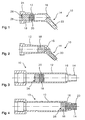
- the syringe 10 shown in Fig. 1 has a cylindrical Part 12, to which an expulsion nozzle 14 connects, a smaller one compared to the cylindrical part 12 Has internal cross section.
- the transition between the cylindrical part 12 and the expulsion nozzle 14 is through formed a guide cone 16.
- the syringe 10 also has a piston 18 which consists of a dimensionally stable material.
- the piston 18 closes an expulsion body 20 made of a deformable material. Further is in the syringe including the dispensing nozzle Filling space 22 is provided for dental mass, the syringe in the Hibernation is not yet filled.
- the better accessibility due to tooth cavities and manageability is the expulsion nozzle 14 opposite the axis of the piston 18 and cylindrical Part 12 angled.
- the piston 18 is from a piston rod, not shown operable, which is part of a syringe holder, the is also not shown.
- the syringe holder engages behind paragraphs 24 on the cylindrical part 12 of the syringe 10 while the piston rod acts on a pressure surface 26 of the piston 18.
- the piston 18 is as comparatively long pistons depicted what the shape retention benefits. Basically, however, material savings can be made the piston may be significantly shorter, for example, only about a third of its diameter. Because of the elasticity of the expulsion body 20 acts as a sealing element, so that the piston 18 basically the uniform pressure distribution serves on the back of the expeller 20. If necessary can the piston 18 also by hand by coating the Expulsion body 20 realized with a dimensionally stable material become.
- the syringe 10 has on her rear end of an insertion cone 28. This enables easily the introduction of the expulsion body 20 and Piston 18 existing part, even if the expeller 20 in a relaxed state compared to the inner diameter of the cylindrical Part 12 has an oversize.
- the expulsion body 20 is preferably cylindrical in the relaxed state. If desired, he can be in a relaxed state its outer surface also has a flat cone his. Then the internal pressure on the piston 18 adjacent Area larger, which benefits the sealing effect. Further it is possible to one at the tip of the expeller 20 to put a rather blunt cone, at least one Larger cone angle than the cone angle of the guide cone 16 should have.
- the expulsion body 20 is like this highly deformable so that when the Dental mass 22 from the syringe 20 the entire interior of Fills guide cone 16 and expulsion nozzle 14.
- the expulsion nozzle 14 has a cylindrical inner shape on, it being understood that the diameter of the Expulsion nozzle 14 in a modified embodiment, too can easily lose weight.
- the piston 18 just touches in the state in which the expulsion body 20 has the expulsion nozzle 14 completely fills the guide cone 16. So the guide cone 16 also forms a stop for the Piston 18 and a signal to the user that another Expulsion is not possible and the existing dental mass is exhausted. As can also be seen from FIG. 2, remains no dental mass in the area of the guide cone 16 and dispensing nozzle 14. The syringe is now completely empty and can be discarded as a single part.
- FIG. 3 shows a further embodiment of an inventive one Syringe visible.
- the expulsion connector 14 coaxially in the cylindrical part 12.
- the difference in diameter between the expulsion nozzle 10 and the cylindrical part 12 less serious than in the 1 and 2 shown embodiment of the invention Syringe 10.
- the Guide cone 16 with a flatter cone angle so that a less deformation of the expulsion body 20 is required.
- This syringe 10, which is filled in FIG. 3 and in FIG. 4 in emptied state is for a screw actuation provided, the elements of which are known per se, but here are not shown in detail.
- the piston 18 also has here a printing surface 26 and immediately adjoins the expulsion body 20.
- the expulsion body 20 is elastic deformable and becomes 16 when penetrating into the guide cone automatically tapers to the diameter of the expulsion nozzle 14, as can be seen from Fig. 4.
- the piston 18 and Expulsion body 20 existing part after loosening the screw rod for the plunger to be pushed back and the syringe to be refilled to reuse the screw drive to enable. It is understood that it is preferred that if necessary, the piston and expeller body Unit can be replaced.
Landscapes
- Health & Medical Sciences (AREA)
- Engineering & Computer Science (AREA)
- Mechanical Engineering (AREA)
- General Health & Medical Sciences (AREA)
- Veterinary Medicine (AREA)
- Epidemiology (AREA)
- Life Sciences & Earth Sciences (AREA)
- Animal Behavior & Ethology (AREA)
- Oral & Maxillofacial Surgery (AREA)
- Public Health (AREA)
- Dentistry (AREA)
- Physics & Mathematics (AREA)
- Geometry (AREA)
- Dental Tools And Instruments Or Auxiliary Dental Instruments (AREA)
- Infusion, Injection, And Reservoir Apparatuses (AREA)
- Coating Apparatus (AREA)
- Injection Moulding Of Plastics Or The Like (AREA)
Claims (21)
- Seringue pour masses visqueuses, notamment masses dentaires durcissant à la lumière, avec une tubulure d'expulsion et un corps d'expulsion qui peut être introduit au moins partiellement dans la tubulure d'expulsion pour expulser la masse, caractérisée en ce que le corps d'expulsion (20) est déformable en s'adaptant à la forme de la tubulure d'expulsion (14) et est conçu de façon indéformable à son extrémité arrière.
- Seringue pour masses visqueuses selon la revendication 1, caractérisée en ce que le corps d'expulsion (20) est déformable élastiquement.
- Seringue selon la revendication 1, caractérisée en ce que le corps d'expulsion (20) passe sur son extrémité arrière dans un piston (18) ou forme celui-ci, qui présente un diamètre extérieur qui est adapté au diamètre intérieur de la partie cylindrique (12) de la seringue (10) et sur son extrémité avant est conçu pour pénétrer au moins partiellement en se déformant dans la tubulure d'expulsion (14).
- Seringue selon la revendication 1, caractérisée en ce que la tubulure d'expulsion (14) présente vers son extrémité de sortie une section transversale constante ou se rétrécissant et se termine en particulier de façon conique.
- Seringue selon l'une des revendications précédentes, caractérisée en ce que la tubulure d'expulsion (14) présente une section transversale amincie par rapport à la partie cylindrique (12) de la seringue (10).
- Seringue selon l'une des revendications précédentes, caractérisée en ce qu'entre la partie cylindrique (12) de la seringue (10) et la tubulure d'expulsion (14), un cône de guidage (16) est conçu pour la déformation du corps d'expulsion (20).
- Seringue selon l'une des revendications précédentes, caractérisée en ce que le corps d'expulsion (20) est fixé à un piston (18), notamment collé.
- Seringue selon l'une des revendications précédentes, caractérisée en ce que le volume du corps d'expulsion (20) correspond essentiellement au volume d'un cône de guidage (16) et de la tubulure d'expulsion (14).
- Seringue selon l'une des revendications précédentes, caractérisée en ce que le corps d'expulsion (20) déformable élastiquement présente sur son extrémité arrière une plaque de guidage pour former un piston, avec laquelle la fonction d'étanchéité par rapport au cylindre de seringue (12) peut être garantie.
- Seringue selon l'une des revendications précédentes, caractérisée en ce que le corps d'expulsion (20) est composé de silicone ou d'un autre élastomère avec une dureté Shore de 10 à 90, de préférence de 20 à 60.
- Seringue selon l'une des revendications précédentes, caractérisée en ce que le corps d'expulsion (20) présente dans l'état détendu une pointe d'expulsion, dont l'angle de conicité est plus grand que l'angle de conicité du piston d'expulsion (14).
- Seringue selon l'une des revendications précédentes, caractérisée en ce que le corps d'expulsion (20) présente un piston (18) essentiellement déformable et une partie élastique fixée au piston (18) qui peut être introduite dans le piston d'expulsion (14) et avec laquelle la masse visqueuse peut être expulsée presque intégralement du piston d'expulsion (14).
- Seringue selon l'une des revendications précédentes, caractérisée en ce que la partie élastique du corps d'expulsion (20), notamment sur son extrémité arrière, présente un excédent destiné à former un joint à lèvres par rapport au diamètre intérieur de la partie cylindrique (12) de la seringue (10).
- Seringue selon l'une des revendications précédentes, caractérisée en ce que la tubulure d'expulsion (14) est coudée par rapport à la partie cylindrique (12) de la seringue (10), notamment selon un angle de 45° environ, et le corps d'expulsion (20) s'étend dans un état entièrement vidé de la seringue dans la tubulure d'expulsion (14).
- Seringue selon l'une des revendications précédentes, caractérisée en ce que le corps d'expulsion (20) est conçu comme une partie remplie de fluide, notamment une partie remplie d'hydrogel.
- Seringue selon l'une des revendications précédentes, caractérisée en ce que le corps d'expulsion (20) et un piston (18) sont conçus d'une seule pièce en matière synthétique et le côté du piston est fabriqué par durcissement ultérieur, notamment par réticulation partielle.
- Seringue selon l'une des revendications précédentes, caractérisée en ce que le corps d'expulsion (20) est inséré comme partie séparée du piston (18) dans la seringue (10) par un piston (18).
- Seringue, contenant une masse visqueuse, avec une tubulure d'expulsion et avec un corps d'expulsion, qui peut être introduite au moins partiellement dans la tubulure d'expulsion pour expulser la masse, caractérisée par les parties caractérisantes de la revendication 1 et en particulier également par les parties caractérisantes d'une des revendications 2 à 16.
- Procédé de fabrication d'une seringue pour masses visqueuses, avec une partie cylindrique de la seringue et une tubulure d'expulsion s'y raccordant, la partie cylindrique de la seringue guidant un piston et un corps d'expulsion étant prévu devant le piston pour expulser la masse, qui peut être introduit au moins partiellement dans la tubulure d'expulsion, caractérisé en ce que le corps d'expulsion, notamment dans des techniques d'injection à 2 couches, est fabriqué avec une couche comparativement dure et une couche comparativement élastique, la partie avant du corps d'expulsion étant destinée à pénétrer dans la tubulure d'expulsion, étant formée par la zone de la couche élastique.
- Procédé selon la revendication 18, caractérisé en ce que la couche double prévue pour la constitution du corps d'expulsion est soumise à un procédé de découpe à la matrice, et les corps d'expulsion découpés à la matrice sont mis en place individuellement dans une seringue.
- Procédé selon l'une des revendications 18 ou 19, caractérisé en ce que le corps d'expulsion est traité ultérieurement, notamment réticulé a posteriori, pour produire un côté partiellement dur.
Applications Claiming Priority (2)
| Application Number | Priority Date | Filing Date | Title |
|---|---|---|---|
| DE19651981A DE19651981C1 (de) | 1996-12-13 | 1996-12-13 | Spritze für viskose Massen und Verfahren zur Herstellung einer Spritze für viskose Massen |
| DE19651981 | 1996-12-13 |
Publications (2)
| Publication Number | Publication Date |
|---|---|
| EP0848935A1 EP0848935A1 (fr) | 1998-06-24 |
| EP0848935B1 true EP0848935B1 (fr) | 2004-07-14 |
Family
ID=7814673
Family Applications (1)
| Application Number | Title | Priority Date | Filing Date |
|---|---|---|---|
| EP97118900A Expired - Lifetime EP0848935B1 (fr) | 1996-12-13 | 1997-10-30 | Seringue |
Country Status (5)
| Country | Link |
|---|---|
| EP (1) | EP0848935B1 (fr) |
| JP (1) | JPH10179609A (fr) |
| AT (1) | ATE270856T1 (fr) |
| CA (1) | CA2221832C (fr) |
| DE (2) | DE19651981C1 (fr) |
Families Citing this family (14)
| Publication number | Priority date | Publication date | Assignee | Title |
|---|---|---|---|---|
| DE19945706C2 (de) | 1999-09-23 | 2002-11-28 | Ivoclar Vivadent Ag | Kartusche und Dentalapplikator |
| US6503084B2 (en) | 2000-02-24 | 2003-01-07 | Dentsply Detrey G.M.B.H. | Method for dispensing dental materials |
| DE10017475A1 (de) * | 2000-04-07 | 2001-10-25 | Degussa | Einwegbehälter für dentales Füllungsmaterial |
| US6379152B1 (en) * | 2000-04-19 | 2002-04-30 | Centrix, Inc. | Dental capsule for placement of ultra-high viscosity dental composite material |
| AU2003200509A1 (en) | 2002-02-27 | 2003-09-11 | Centrix, Inc | Dental capsule for placement of high viscosity dental composite material with reduced extrusion force |
| DE10218859B4 (de) * | 2002-04-26 | 2006-05-24 | Heraeus Kulzer Gmbh | Kapsel aus Kunststoff zur Aufbewahrung und Abgabe von Dentalmaterial |
| US7320596B2 (en) * | 2002-12-09 | 2008-01-22 | Dentsply International Inc. | Cartridge for viscuos dental material |
| DE102005011643A1 (de) | 2005-03-14 | 2006-11-16 | Ivoclar Vivadent Ag | Kartusche zum Lagern und Ausbringen einer Masse |
| KR100976820B1 (ko) | 2008-12-24 | 2010-08-20 | 김대연 | 상악동 점막 거상용 액체 주입장치 및 그를 이용한 상악동 점막 거상 방법 |
| DE202010015594U1 (de) * | 2010-07-30 | 2011-05-05 | Spreizer, Heinrich | Kapsel und Kolben |
| DE102018118577A1 (de) | 2018-07-31 | 2020-02-06 | Voco Gmbh | Vorrichtung zur Aufnahme und Applikation von Dentalmaterial und Verfahren |
| DE102018126140B4 (de) | 2018-10-22 | 2023-12-07 | Voco Gmbh | Vorrichtung mit einem thermochromen Temperaturindikator zur Aufnahme, Erwärmung und Applikation von Dentalmaterialien |
| CN112778057A (zh) * | 2021-01-08 | 2021-05-11 | 彭贵阳 | 一种石斛有机肥的加工方法 |
| DE102021103980A1 (de) | 2021-02-19 | 2022-08-25 | Universität Rostock, Körperschaft des öffentlichen Rechts | Anordnung zur Aufnahme und/oder Applikation eines Dentalkomposits |
Family Cites Families (5)
| Publication number | Priority date | Publication date | Assignee | Title |
|---|---|---|---|---|
| GB298292A (en) * | 1927-07-18 | 1928-10-11 | Reginald Baxter | Improvements in or relating to syringes |
| US2903794A (en) * | 1956-05-07 | 1959-09-15 | Arthur B Carfagni | Amalgam carrier and dispenser |
| US3900954A (en) * | 1974-07-10 | 1975-08-26 | William B Dragan | Dental filling gun and nozzle tip therefor |
| US5484734A (en) * | 1993-03-09 | 1996-01-16 | Torc Seimitsu Industries, Ltd. | Reaction vessel for preventing evaporation and a method thereof |
| NZ286445A (en) * | 1995-05-16 | 1997-12-19 | Ivac Corp | Needleless luer connector: deformable piston occludes bore |
-
1996
- 1996-12-13 DE DE19651981A patent/DE19651981C1/de not_active Expired - Fee Related
-
1997
- 1997-10-30 DE DE59711776T patent/DE59711776D1/de not_active Expired - Lifetime
- 1997-10-30 AT AT97118900T patent/ATE270856T1/de not_active IP Right Cessation
- 1997-10-30 EP EP97118900A patent/EP0848935B1/fr not_active Expired - Lifetime
- 1997-11-21 CA CA002221832A patent/CA2221832C/fr not_active Expired - Fee Related
- 1997-12-13 JP JP9362916A patent/JPH10179609A/ja active Pending
Also Published As
| Publication number | Publication date |
|---|---|
| CA2221832C (fr) | 2003-06-17 |
| EP0848935A1 (fr) | 1998-06-24 |
| JPH10179609A (ja) | 1998-07-07 |
| DE59711776D1 (de) | 2004-08-19 |
| ATE270856T1 (de) | 2004-07-15 |
| DE19651981C1 (de) | 1998-07-23 |
| CA2221832A1 (fr) | 1998-06-13 |
Similar Documents
| Publication | Publication Date | Title |
|---|---|---|
| EP0848935B1 (fr) | Seringue | |
| EP0220551B1 (fr) | Seringue pour l'application de masses dentaires et son procédé de fabrication | |
| DE69004824T2 (de) | Kapsel. | |
| EP0645122B1 (fr) | Seringue de dosage de substances visqueuses, en particulier de substances dentaires | |
| DE60129431T2 (de) | Medizinische vorrichtung | |
| EP0470393B1 (fr) | Séringue pour granulés | |
| DE69419021T2 (de) | Spritze zum abgeben viskoser materialien | |
| DE69915373T2 (de) | Kartusche zum spenden von flüssigen zusammensetzungen | |
| DE2528116C2 (de) | Amalgamspritze sowie Mundstück für eine Amalgamspritze | |
| DE69423112T2 (de) | Dentaler patronenextruder mit einer starren stirnseite | |
| DE69735642T2 (de) | Abgabespitze mit Faserende | |
| DE69635354T2 (de) | Patrone zum Ausbringen von Zahnmaterialien | |
| EP0022987B1 (fr) | Seringue | |
| DE69420561T2 (de) | Zahnärztliche spritze und patrone hierfür | |
| EP0657143A1 (fr) | Seringue de dosage pre-remplie avec une composition dentaire | |
| EP2050477B1 (fr) | Unité d'ampoule dotée d'un adaptateur | |
| EP0627200A2 (fr) | Capsule mélangeuse pour produits dentaires | |
| EP0645124A1 (fr) | Seringue de dosage de substances visqueuses, en particulier de substances dentaires | |
| DE4119522A1 (de) | Manueller extruder und patrone fuer viskoses zahnmaterial | |
| DE60304253T2 (de) | Austragkartusche | |
| DE102010036782A1 (de) | Kapsel und Kolben | |
| DE3005855A1 (de) | Bodenverschluss fuer einen hohlzylindrischen strangpressbehaelter | |
| DE3217044A1 (de) | Behaelter fuer plastische massen | |
| EP1212984A1 (fr) | Seringue pour l'administration dosée de produits dentaires | |
| DE4414019C1 (de) | Nachfüllpatrone für einen durch Bestreichen einer Oberfläche Produkt abgebenden Stift sowie Verfahren zum Befüllen derselben |
Legal Events
| Date | Code | Title | Description |
|---|---|---|---|
| PUAI | Public reference made under article 153(3) epc to a published international application that has entered the european phase |
Free format text: ORIGINAL CODE: 0009012 |
|
| AK | Designated contracting states |
Kind code of ref document: A1 Designated state(s): AT CH DE FR GB IT LI SE |
|
| AX | Request for extension of the european patent |
Free format text: AL;LT;LV;RO;SI |
|
| 17P | Request for examination filed |
Effective date: 19980609 |
|
| AKX | Designation fees paid |
Free format text: AT CH DE FR GB IT LI SE |
|
| RBV | Designated contracting states (corrected) |
Designated state(s): AT CH DE FR GB IT LI SE |
|
| RAP1 | Party data changed (applicant data changed or rights of an application transferred) |
Owner name: IVOCLAR VIVADENT AG |
|
| 17Q | First examination report despatched |
Effective date: 20030407 |
|
| GRAP | Despatch of communication of intention to grant a patent |
Free format text: ORIGINAL CODE: EPIDOSNIGR1 |
|
| GRAS | Grant fee paid |
Free format text: ORIGINAL CODE: EPIDOSNIGR3 |
|
| GRAA | (expected) grant |
Free format text: ORIGINAL CODE: 0009210 |
|
| AK | Designated contracting states |
Kind code of ref document: B1 Designated state(s): AT CH DE FR GB IT LI SE |
|
| REG | Reference to a national code |
Ref country code: GB Ref legal event code: FG4D Free format text: NOT ENGLISH |
|
| REG | Reference to a national code |
Ref country code: CH Ref legal event code: EP |
|
| REG | Reference to a national code |
Ref country code: SE Ref legal event code: TRGR |
|
| REG | Reference to a national code |
Ref country code: CH Ref legal event code: NV Representative=s name: KELLER & PARTNER PATENTANWAELTE AG |
|
| REF | Corresponds to: |
Ref document number: 59711776 Country of ref document: DE Date of ref document: 20040819 Kind code of ref document: P |
|
| GBT | Gb: translation of ep patent filed (gb section 77(6)(a)/1977) |
Effective date: 20041021 |
|
| ET | Fr: translation filed | ||
| PLBE | No opposition filed within time limit |
Free format text: ORIGINAL CODE: 0009261 |
|
| STAA | Information on the status of an ep patent application or granted ep patent |
Free format text: STATUS: NO OPPOSITION FILED WITHIN TIME LIMIT |
|
| 26N | No opposition filed |
Effective date: 20050415 |
|
| PGFP | Annual fee paid to national office [announced via postgrant information from national office to epo] |
Ref country code: AT Payment date: 20050812 Year of fee payment: 9 |
|
| PG25 | Lapsed in a contracting state [announced via postgrant information from national office to epo] |
Ref country code: AT Free format text: LAPSE BECAUSE OF NON-PAYMENT OF DUE FEES Effective date: 20061030 |
|
| REG | Reference to a national code |
Ref country code: CH Ref legal event code: PCAR Free format text: NEW ADDRESS: EIGERSTRASSE 2 POSTFACH, 3000 BERN 14 (CH) |
|
| REG | Reference to a national code |
Ref country code: FR Ref legal event code: PLFP Year of fee payment: 19 |
|
| REG | Reference to a national code |
Ref country code: FR Ref legal event code: PLFP Year of fee payment: 20 |
|
| REG | Reference to a national code |
Ref country code: DE Ref legal event code: R079 Ref document number: 59711776 Country of ref document: DE Free format text: PREVIOUS MAIN CLASS: A61C0005060000 Ipc: A61C0005600000 |
|
| PGFP | Annual fee paid to national office [announced via postgrant information from national office to epo] |
Ref country code: FR Payment date: 20161011 Year of fee payment: 20 Ref country code: CH Payment date: 20161013 Year of fee payment: 20 Ref country code: GB Payment date: 20161011 Year of fee payment: 20 Ref country code: DE Payment date: 20161010 Year of fee payment: 20 |
|
| PGFP | Annual fee paid to national office [announced via postgrant information from national office to epo] |
Ref country code: IT Payment date: 20160928 Year of fee payment: 20 Ref country code: SE Payment date: 20161011 Year of fee payment: 20 |
|
| REG | Reference to a national code |
Ref country code: DE Ref legal event code: R071 Ref document number: 59711776 Country of ref document: DE |
|
| REG | Reference to a national code |
Ref country code: CH Ref legal event code: PL |
|
| REG | Reference to a national code |
Ref country code: GB Ref legal event code: PE20 Expiry date: 20171029 |
|
| PG25 | Lapsed in a contracting state [announced via postgrant information from national office to epo] |
Ref country code: GB Free format text: LAPSE BECAUSE OF EXPIRATION OF PROTECTION Effective date: 20171029 |