EP0848975A2 - Verfahren zur Abtrennung einzelner Komponenten aus motorischem Kraftstoff - Google Patents
Verfahren zur Abtrennung einzelner Komponenten aus motorischem Kraftstoff Download PDFInfo
- Publication number
- EP0848975A2 EP0848975A2 EP97116313A EP97116313A EP0848975A2 EP 0848975 A2 EP0848975 A2 EP 0848975A2 EP 97116313 A EP97116313 A EP 97116313A EP 97116313 A EP97116313 A EP 97116313A EP 0848975 A2 EP0848975 A2 EP 0848975A2
- Authority
- EP
- European Patent Office
- Prior art keywords
- components
- separation
- separated
- fuel
- adsorption
- Prior art date
- Legal status (The legal status is an assumption and is not a legal conclusion. Google has not performed a legal analysis and makes no representation as to the accuracy of the status listed.)
- Withdrawn
Links
Images


Classifications
-
- C—CHEMISTRY; METALLURGY
- C10—PETROLEUM, GAS OR COKE INDUSTRIES; TECHNICAL GASES CONTAINING CARBON MONOXIDE; FUELS; LUBRICANTS; PEAT
- C10G—CRACKING HYDROCARBON OILS; PRODUCTION OF LIQUID HYDROCARBON MIXTURES, e.g. BY DESTRUCTIVE HYDROGENATION, OLIGOMERISATION, POLYMERISATION; RECOVERY OF HYDROCARBON OILS FROM OIL-SHALE, OIL-SAND, OR GASES; REFINING MIXTURES MAINLY CONSISTING OF HYDROCARBONS; REFORMING OF NAPHTHA; MINERAL WAXES
- C10G25/00—Refining of hydrocarbon oils in the absence of hydrogen, with solid sorbents
-
- B—PERFORMING OPERATIONS; TRANSPORTING
- B01—PHYSICAL OR CHEMICAL PROCESSES OR APPARATUS IN GENERAL
- B01D—SEPARATION
- B01D15/00—Separating processes involving the treatment of liquids with solid sorbents; Apparatus therefor
Definitions
- the invention relates to a method for separating individual components Motor fuel according to the preamble of claim 1.
- Chromatographic methods for separating individual fuel fractions by adsorption are known from chemical analysis.
- a sample with the fuel components to be separated is injected once into a constant stream of carrier liquid which flows through an adsorption device in the form of a separation column.
- concentration of the fuel components in the carrier liquid is well below 1%.
- the fuel components are temporarily bound to the adsorption material within the separation column, but are then released again and then leave the separation column. Due to the specific interaction properties between the adsorbent material and the fuel components, this bond lasts for different lengths of time for the individual fuel components. As a result, the fuel components leave the separation column at different times, which ultimately leads to separation.
- the driving force for the releasing of the fuel components that are temporarily adsorbed in the separation column is the fact that carrier liquid (without fuel components) is constantly fed into the separation column. In order to maintain the balance between the adsorption material and the carrier liquid despite the tracking of the carrier liquid, the described re-release of the fuel components takes place.
- the object of the invention is a method for separating individual components to create from a motor fuel, building volume and Low weight according to the application on board a motor vehicle can be held.
- the separation takes place by means of selective liquid phase adsorption, the fuel being fed to the adsorption device undiluted.
- the fuel components to be separated are inferior regeneration of the adsorption material.
- the fuel components to be separated immediately after passing through the Adsorption device before.
- Solids with a high surface area are generally suitable as adsorption material, in particular Al 2 O 3 , SiO 2 (silica gel), TiO 2 , ZrO 2 , zeolites or activated carbon.
- the method according to the invention enables a simple and compact construction of the adsorber module. There is no need for complex components. As a result, construction volume and weight can be kept small.
- a major advantage of the method is that in the event of adsorption of the components to be separated, they can be made available immediately when the engine is started. This eliminates the need for a storage tank for the processed fuel.
- the method of liquid phase adsorption according to the invention is suitable on the basis of the advantages mentioned especially for use in mobile systems, like passenger and commercial vehicles.
- the low-boiling fuel components which are added to the gasoline engine in order to reduce the hydrocarbon emissions of gasoline engines in the cold start phase can be separated off.
- Low-boiling components are to be understood in particular as those components with a boiling point lower than 80 ° C.
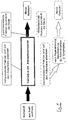
- Fig. 1 shows the basic structure of the method according to the invention using the example the separation of low-boiling fuel components.
- the fuel out the separation column with the adsorption material passes through the fuel tank.
- adsorption material it is possible to use the low-boiling or to adsorb the high-boiling fractions. If the high-boiling fractions are adsorbed, the low-boiling fractions are immediately available at the outlet of the separation column and can be injected into the motor will.
- the adsorption material has a temporary separation performance and must can be regenerated after some time by thermal treatment.
- the regeneration can in a particularly advantageous embodiment by thermostatting by means of the coolant circuit (80 ° C) in the vehicle.
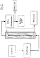
- Fig. 2 shows a schematic representation of an adsorption device in the Form of a separation column, the interior of which is filled with the adsorbent material.
- the fuel mixture to be separated is undiluted in the entrance of the separation column and given to the adsorbent material.
- the non-adsorbed fuel components leave the column on the opposite as an eluate The End.
- the separation column is surrounded by an annular channel that is supported by a heat transfer medium is flowed through for the temperature control of the separation column.
- FIG. 3 shows an experimental setup for determining the adsorber properties and the adsorber capacity shown.
- the fuel is taken from a storage container and via an HPLC pump (max. flow 10 ml / min) through the thermostatted Adsorption column promoted.
- HPLC pump max. flow 10 ml / min
- a Refractometers track the separation performance online. For a quantitative analysis the eluate can be examined offline by gas chromatography.
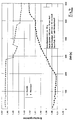
- FIG. 4 shows a comparison of the separation performance of two adsorption materials over a column operating time of 600 seconds (column dimensions: 290 mm * 16 mm for zeolite as adsorption material, 250 mm * 16 mm for silica gel as adsorption material, mass of the adsorption material: 40 g, flow rate: 1ml / min petrol).
- the refractive index of the eluate is plotted as the measured variable.
- the reference fuel commercially available petrol
- a higher refractive index in the eluate indicates an enrichment high-boiling components, a lower refractive index indicates an accumulation of low-boiling components.
Landscapes
- Chemical & Material Sciences (AREA)
- Chemical Kinetics & Catalysis (AREA)
- Oil, Petroleum & Natural Gas (AREA)
- Analytical Chemistry (AREA)
- Engineering & Computer Science (AREA)
- General Chemical & Material Sciences (AREA)
- Organic Chemistry (AREA)
- Exhaust Gas After Treatment (AREA)
- Fuel-Injection Apparatus (AREA)
- Solid-Sorbent Or Filter-Aiding Compositions (AREA)
Abstract
Description
Treibende Kraft für das Wiederfreisetzen der in der Trennsäule zeitweise adsorbierten Kraftstoffkomponenten ist die Tatsache, daß ständig Trägerflüssigkeit (ohne Kraftstoffkomponenten) in die Trennsäule nachgeführt wird. Um trotz der Nachführung der Tragerflüssigkeit das Gleichgewicht zwischen Adsorptionsmaterial und der Trägerflüssigkeit aufrecht zu erhalten, erfolgt die beschriebene Wiederfreisetzung der Kraftstoffkomponenten.
Ein wesentlicher Vorteil des Verfahrens besteht darin, daß im Falle der Adsorption der abzutrennenden Komponenten diese sofort beim Starten des Motors bereitgestellt werden können. Dadurch entfällt die Notwendigkeit eines Vorratstanks für den aufbereiteten Kraftstoff.
- zum Einstellen von Motorbetriebsphasen mit höherer Motorkompression;
- als Reduktionsmittel zur katalytischen Entstickung von motorischen Abgasen;
- zur Absenken der Anspringtemperatur von Abgasnachbehandlungskatalysatoren.
- Fig. 1
- den prinzipiellen Aufbau des erfindungsgemäßen Verfahrens;
- Fig. 2
- eine Vorrichtung zur Durchführung des erfindungsgemäßen Verfahrens;
- Fig. 3
- einen Versuchsaufbau zur Bestimmung der Adsorbereigenschaften und Adsorberkapazität;
- Fig. 4
- eine Vergleich der Trennleistung zweier Adsorptionsmaterialien;
- Fig. 5,6
- die Konzentration einzelner Kraftstoffkomponenten am Ausgang der Adsorptionsvorrichtung.
Claims (10)
- Verfahren zur Abtrennung einzelner Komponenten aus motorischem Kraftstoff, wobei die Abtrennung mittels selektiver Flüssigphasen-Adsorption erfolgt, dadurch gekennzeichnet, daß der Kraftstoff unverdünnt der Adsorptionsvorrichtung zugeführt wird und entwederdie abzutrennenden Komponenten in der Adsorptionsvorrichtung adsorbiert werden und das Adsorptionsmaterial der Adsorptionsvorrichtung anschließend regeneriert wird, oderdie abzutrennenden Komponenten die Adsorptionsvorrichtung durchlaufen, und die übrigen Komponenten in der Adsorptionsvorrichtung adsorbiert werden.
- Verfahren nach Anspruch 1, dadurch gekennzeichnet, daß das Adsorptionsmaterial eine innere Oberfläche von 10 bis 1600 m2/g aufweist.
- Verfahren nach einem der vorangehenden Ansprüche, dadurch gekennzeichnet, daß das Adsorptionsmaterial Al2O3, SiO2, TiO2, ZrO2, Aktivkohle oder ein Zeolith ist.
- Verfahren nach einem der vorangehenden Ansprüche, dadurch gekennzeichnet, daß die abzutrennten Komponenten nach erfolgter Abtrennung zwischengespeichert werden.
- Verfahren nach einem der vorangehenden Ansprüche, dadurch gekennzeichnet, daß die abzutrennenden Komponenten unmittelbar nach erfolgter Abtrennung genutzt werden.
- Verfahren nach einem der vorangehenden Ansprüche, dadurch gekennzeichnet, daß es an Bord eines Kraftfahrzeuges durchgeführt wird.
- Verfahren nach einem der vorangehenden Ansprüche, dadurch gekennzeichnet, daß die abzutrennenden Kraftstoffkomponenten niedersiedende Kraftstoff-Komponenten sind, welche nach erfolgter Abtrennung zur Absenkung der Kohlenwasserstoff-Emissionen in der Kaltstartphase einem Ottomotor zugegeben werden.
- Verfahren nach einem der vorangehenden Ansprüche, dadurch gekennzeichnet, daß die abzutrennenden Komponenten nach erfolgter Abtrennung zum Einstellen von Motorbetriebsphasen mit höherer Motorkompression genutzt werden.
- Verfahren nach einem der vorangehenden Ansprüche, dadurch gekennzeichnet, daß die abzutrennenden Komponenten nach erfolgter Abtrennung als Reduktionsmittel zur katalytischen Entstickung von motorischen Abgasen genutzt werden.
- Verfahren nach einem der vorangehenden Ansprüche, dadurch gekennzeichnet, daß die abzutrennenden Komponenten nach erfolgter Abtrennung zur Absenkung der Anspringtemperatur von Abgasnachbehandlungskatalysatoren genutzt werden.
Applications Claiming Priority (2)
| Application Number | Priority Date | Filing Date | Title |
|---|---|---|---|
| DE1996152681 DE19652681C1 (de) | 1996-12-18 | 1996-12-18 | Verfahren zur Abtrennung einzelner Komponenten aus motorischem Kraftstoff |
| DE19652681 | 1996-12-18 |
Publications (2)
| Publication Number | Publication Date |
|---|---|
| EP0848975A2 true EP0848975A2 (de) | 1998-06-24 |
| EP0848975A3 EP0848975A3 (de) | 1998-12-16 |
Family
ID=7815132
Family Applications (1)
| Application Number | Title | Priority Date | Filing Date |
|---|---|---|---|
| EP97116313A Withdrawn EP0848975A3 (de) | 1996-12-18 | 1997-09-19 | Verfahren zur Abtrennung einzelner Komponenten aus motorischem Kraftstoff |
Country Status (2)
| Country | Link |
|---|---|
| EP (1) | EP0848975A3 (de) |
| DE (1) | DE19652681C1 (de) |
Cited By (2)
| Publication number | Priority date | Publication date | Assignee | Title |
|---|---|---|---|---|
| DE102008044306A1 (de) * | 2008-12-03 | 2010-06-10 | Robert Bosch Gmbh | Vorrichtung zur Stabilisierung eines Betriebsfluides für Kraftfahrzeuge |
| WO2019152291A1 (en) * | 2018-01-31 | 2019-08-08 | Saudi Arabian Oil Company | Adsorption-based fuel systems for onboard cetane on-demand and octane on-demand |
Families Citing this family (3)
| Publication number | Priority date | Publication date | Assignee | Title |
|---|---|---|---|---|
| DE19845397C2 (de) * | 1998-10-02 | 2000-09-14 | Daimler Chrysler Ag | Verfahren zur Entschwefelung eines motorischen Kraftstoffs an Bord eines Kraftfahrzeugs |
| DE19927174C1 (de) * | 1999-06-15 | 2000-10-12 | Daimler Chrysler Ag | Kraftstoffversorgungsanlage |
| DE102006039581B4 (de) * | 2006-08-23 | 2017-07-06 | Mahle International Gmbh | Kraftstofffilter |
Family Cites Families (5)
| Publication number | Priority date | Publication date | Assignee | Title |
|---|---|---|---|---|
| GB1099839A (en) * | 1965-11-04 | 1968-01-17 | British Petroleum Co | Improvements relating to the separation of hydrocarbon mixtures |
| US3831572A (en) * | 1972-10-04 | 1974-08-27 | Chevron Res | Single-stage cold start and evaporative control method and apparatus for carrying out same |
| US3906915A (en) * | 1973-03-29 | 1975-09-23 | Gen Motors Corp | Dual fuel system and method |
| US5186819A (en) * | 1991-07-15 | 1993-02-16 | Exxon Research And Engineering Company | Benzene removal from gasoline boiling range streams |
| US5207734A (en) * | 1991-07-22 | 1993-05-04 | Corning Incorporated | Engine exhaust system for reduction of hydrocarbon emissions |
-
1996
- 1996-12-18 DE DE1996152681 patent/DE19652681C1/de not_active Expired - Fee Related
-
1997
- 1997-09-19 EP EP97116313A patent/EP0848975A3/de not_active Withdrawn
Cited By (3)
| Publication number | Priority date | Publication date | Assignee | Title |
|---|---|---|---|---|
| DE102008044306A1 (de) * | 2008-12-03 | 2010-06-10 | Robert Bosch Gmbh | Vorrichtung zur Stabilisierung eines Betriebsfluides für Kraftfahrzeuge |
| WO2019152291A1 (en) * | 2018-01-31 | 2019-08-08 | Saudi Arabian Oil Company | Adsorption-based fuel systems for onboard cetane on-demand and octane on-demand |
| CN111771049A (zh) * | 2018-01-31 | 2020-10-13 | 沙特阿拉伯石油公司 | 用于车载按需十六烷和按需辛烷的基于吸附的燃料系统 |
Also Published As
| Publication number | Publication date |
|---|---|
| EP0848975A3 (de) | 1998-12-16 |
| DE19652681C1 (de) | 1998-04-02 |
Similar Documents
| Publication | Publication Date | Title |
|---|---|---|
| DE19882303B4 (de) | Vorrichtung, Verfahren und System zur Konzentration und Verringerung adsorbierbarer Schadstoffe | |
| DE19845397C2 (de) | Verfahren zur Entschwefelung eines motorischen Kraftstoffs an Bord eines Kraftfahrzeugs | |
| DE69606292T2 (de) | Dieselmotorabgasreinigungssystem | |
| DE69726540T2 (de) | Emissionskontrolle | |
| DE69613967T2 (de) | Verfahren und einrichtung zur behandlung von abgasen | |
| DE69313764T2 (de) | Vorrichtung und Verfahren zur Änderung einer Gasmischung | |
| DE69410260T2 (de) | Verfahren und vorrichtung zur änderung eines brennstoffes zur verringerung von aus brennkraftmaschinen ausgestossenen schadstoffen | |
| DE3928760C2 (de) | ||
| EP1600612B1 (de) | Verfahren zur Entfernung von Stickoxiden und Russpartikeln aus dem mageren Abgas eines Verbrennungsmotors und Abgasreinigungssystem hierfür | |
| DE69303124T2 (de) | System und Methode zur Entfernung von Kohlenwasserstoffen aus Gasströmen unter Verwendung von mehreren Adsorptionsmitteln | |
| DE60130406T3 (de) | Vorrichtung und Verfahren zur Abgasreinigung | |
| DE602004004835T2 (de) | Abgasreinigungsverfahren | |
| EP0848975A2 (de) | Verfahren zur Abtrennung einzelner Komponenten aus motorischem Kraftstoff | |
| JPH10501885A (ja) | 置換クロマトグラフィーを用いて混合物から物質を分離するプロセス | |
| CN1954144A (zh) | 贮存和释放内燃发动机燃料流中含硫芳族化合物的设备和方法 | |
| US5814287A (en) | Polymerization catalyst enhanced hydrocarbon trapping process | |
| EP2668381B1 (de) | Verfahren zum betrieb einer abgasanlage | |
| DE69822939T2 (de) | Verwendung einer Vorrichtung zum Reinigen von Abgasen | |
| EP4341537B1 (de) | Kaltstart-abgasreinigung | |
| DE4340650C2 (de) | Verwendung eines Adsorbens für Kohlenwasserstoffe in Abgasen | |
| EP0864356B1 (de) | Einrichtung zum Nachbehandeln von Abgasen einer fremdgezündeten Brennkraftmaschine | |
| DE2337754A1 (de) | Fraktionierung von gasmischungen | |
| US3358421A (en) | Removal of carbonyl sulfides from hydrocarbon fluids | |
| EP1934135A1 (de) | Reformersystem sowie verfahren zur reformierung | |
| DE10027401A1 (de) | Kleinvolumiger Absorber |
Legal Events
| Date | Code | Title | Description |
|---|---|---|---|
| PUAI | Public reference made under article 153(3) epc to a published international application that has entered the european phase |
Free format text: ORIGINAL CODE: 0009012 |
|
| AK | Designated contracting states |
Kind code of ref document: A2 Designated state(s): AT BE CH DE DK ES FI FR GB GR IE IT LI LU MC NL PT SE |
|
| AX | Request for extension of the european patent |
Free format text: AL;LT;LV;RO;SI |
|
| PUAL | Search report despatched |
Free format text: ORIGINAL CODE: 0009013 |
|
| AK | Designated contracting states |
Kind code of ref document: A3 Designated state(s): AT BE CH DE DK ES FI FR GB GR IE IT LI LU MC NL PT SE |
|
| AX | Request for extension of the european patent |
Free format text: AL;LT;LV;RO;SI |
|
| AKX | Designation fees paid | ||
| STAA | Information on the status of an ep patent application or granted ep patent |
Free format text: STATUS: THE APPLICATION IS DEEMED TO BE WITHDRAWN |
|
| 18D | Application deemed to be withdrawn |
Effective date: 19990617 |
|
| REG | Reference to a national code |
Ref country code: DE Ref legal event code: 8566 |