EP0849015A2 - Mécanisme pour un système de transfert - Google Patents
Mécanisme pour un système de transfert Download PDFInfo
- Publication number
- EP0849015A2 EP0849015A2 EP97122671A EP97122671A EP0849015A2 EP 0849015 A2 EP0849015 A2 EP 0849015A2 EP 97122671 A EP97122671 A EP 97122671A EP 97122671 A EP97122671 A EP 97122671A EP 0849015 A2 EP0849015 A2 EP 0849015A2
- Authority
- EP
- European Patent Office
- Prior art keywords
- movable
- lever
- ball screw
- movable means
- moving
- Prior art date
- Legal status (The legal status is an assumption and is not a legal conclusion. Google has not performed a legal analysis and makes no representation as to the accuracy of the status listed.)
- Granted
Links
- 230000033001 locomotion Effects 0.000 claims abstract description 27
- 230000007246 mechanism Effects 0.000 description 24
- 230000008569 process Effects 0.000 description 12
- 238000000034 method Methods 0.000 description 11
- 238000006073 displacement reaction Methods 0.000 description 5
- 229910052751 metal Inorganic materials 0.000 description 3
- 239000002184 metal Substances 0.000 description 3
- 230000008901 benefit Effects 0.000 description 2
- 229910052782 aluminium Inorganic materials 0.000 description 1
- XAGFODPZIPBFFR-UHFFFAOYSA-N aluminium Chemical compound [Al] XAGFODPZIPBFFR-UHFFFAOYSA-N 0.000 description 1
- 238000010276 construction Methods 0.000 description 1
- 238000001125 extrusion Methods 0.000 description 1
- 230000006872 improvement Effects 0.000 description 1
- 238000012986 modification Methods 0.000 description 1
- 230000004048 modification Effects 0.000 description 1
- 238000011112 process operation Methods 0.000 description 1
- 230000000750 progressive effect Effects 0.000 description 1
- 230000009467 reduction Effects 0.000 description 1
- 230000000630 rising effect Effects 0.000 description 1
Images




Classifications
-
- B—PERFORMING OPERATIONS; TRANSPORTING
- B21—MECHANICAL METAL-WORKING WITHOUT ESSENTIALLY REMOVING MATERIAL; PUNCHING METAL
- B21D—WORKING OR PROCESSING OF SHEET METAL OR METAL TUBES, RODS OR PROFILES WITHOUT ESSENTIALLY REMOVING MATERIAL; PUNCHING METAL
- B21D43/00—Feeding, positioning or storing devices combined with, or arranged in, or specially adapted for use in connection with, apparatus for working or processing sheet metal, metal tubes or metal profiles; Associations therewith of cutting devices
- B21D43/02—Advancing work in relation to the stroke of the die or tool
- B21D43/04—Advancing work in relation to the stroke of the die or tool by means in mechanical engagement with the work
- B21D43/05—Advancing work in relation to the stroke of the die or tool by means in mechanical engagement with the work specially adapted for multi-stage presses
- B21D43/055—Devices comprising a pair of longitudinally and laterally movable parallel transfer bars
Definitions
- the present invention of a mechanical device applied in a transfer system is an improvement of the device in corresponding patents issued in Brazil as No. 8701734 and in the US as No. 4,875,931, by the same inventor/applicant, and it provides a mechanical arrangement used mainly for automating the several processing stations of, for example, a metal stamping processed metal part in a conventional press.
- the main characteristic of this mechanism is its simplicity mainly when compared with other transfer mechanisms used to perform the same operation.
- the present mechanism which is the object of this application, has a very simple mechanism to the closing fingers axis when it reaches a defined displacement point, where it converts the additional travel and control for the lifting fingers or orthogonal movement (usually vertical), resulting therefore in another controlled axis, providing an operational sequence with a relevant cost reduction in the transfer system.
- the present invention uses a driven screw to move the mechanism in a first direction a desired amount to a stopping point while the driven screw continues to rotate and through a lever system causes a part of the mechanism to move in a second direction which is orthogonal to that first direction.
- the traditional and known transfer mechanisms use one drive system with respective controls for each axis. This means for the mostly used and traditional transfer mechanisms the three axis systems have three independent drives and controls, and this represents relevant costs.
- the solution of using one drive system for two displacements movements was the object of the patents described above. In that case it was based in a mechanical driven transfer mechanism. In this present application the basic concept was developed for a servo motor driven and C.N.C. controlled transfer mechanism; however, both mechanisms can be used with any of these drive types. Due mainly to the transfer system prices, most of the existing transfers systems use only two axis motions, one for the closing of the transfers fingers, and another for the pitch or the forward move of the parts between the die stations. After leaving the part in sequence or at the next station, the transfer mechanism opens the fingers and goes backwards to the initial or start point, mainly with one pair of fingers for each die station.
- the operational cycle usually has several steps that complete the operation in a three axis transfer system, represented by an elevated number of mechanical, drive and control systems for each axis of movement. Basically these are the three different steps: a) The fingers move forward to the next die station representing the closing motion, b) the fingers with the parts already picked up lift the parts, representing the lifting motion, and c) the fingers once in the upper position transfers the parts to the next die station. This is the transference movement. The transfer continues its cycle by returning in a different sequence; first lowering the vertical movement the transfer deposits the parts in the next die station, in sequence it opens the fingers and afterwards returns the fingers back to the restart point. The fingers that are usually one pair for each die station are assembled in one pair of rails. Therefore, all the parts are transferred simultaneously between all the die stations.
- the great advantage of the mechanism covered by the present application is the fact that it eliminates one driven and control mechanism system, adding only basically a pivoted lever and without losing any advantage or control of a comparable and traditional known transfer system. Even the cycle time can be slightly improved due to the easy control. Due to this simplicity it became possible to assemble this mechanism in a sub-plate, then four of these sub-plates are assembled two in one side connected with bars and two in the other side also connected with bars representing the basic mechanism for a three axis transfer system.
- the mechanical device applied in a transfer system is basically a mechanical arrangement which is part of a transfer set which has the function to grasp, lift and transport or transfer the parts in a metal stamping process, or any other similar process.
- a transfer set which has the function to grasp, lift and transport or transfer the parts in a metal stamping process, or any other similar process.
- grippers are usually used in pairs, but can be only one, for each process station and are assembled orthogonal, in one or two opposite rails. These rails move forward, upwards and parallel to the process flow direction.
- the present mechanical arrangement uses only one drive system for a two axis motion, or more specifically, uses the drive system to close the grippers and additionally to lift the bars/grippers and parts.
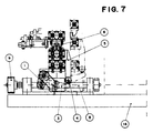
- the mechanical arrangement includes of a lower pin 2, which is attached by a lever 2' to the case 12 of the ball screw 8, a primary lever 1 pivoted on pin 2 and connected by square pin 15 to a secondary lever 3, which at its opposite end is always in contact with a freely turning roller drive 4 that it is installed in the connecting bar 5.
- Bar 5 in turn is connected with the rising structure support rail 7, which holds the pitch linear guide 6.
- This entire set is connected by a longitudinal bar to another similar and parallel assembled set, and usually has a similar arrangement at the opposite side of the process center line. It is driven by a ball screw 8, which has attached a pulley 9.
- This pulley in this present embodiment is driven by a toothed belt, or any other appropriate similar and known drive component, such as a chain, one being driven on both sides, with a connecting crossing bar driving the two axis (rails closing and lifting) for the entire transfer set as shown.
- Another option is to use one motor to drive each side, with no connecting bar between the two sides of the transfer sets.
- the mechanism (which includes as movable means the carriage 16) moves forward and backwards in the longitudinal direction of ball screw 8. Moving forward a predetermined distance, it reaches the stop forward limit 11, which is adjustable for any desired position.
- the ball screw case 12 (Fig. 5), attached to the ball screw, continues to move forward, and the pull by lever 2' starts rotating the lever means including primary lever 1 and lever 3. That is, since pin 15 is square, secondary lever 3 also rotates counter-clockwise.
- the entire cycle made by the transfer die set here described follows a continuous and constant operational synchronism, which basically needs only two power driven units to have the desired three axis motion, being one for driven system for the gripper 13 closing and lifting movements, and another driven system for the pitch or transfer (to next process station) movement.
- This operational transfer cycle basically follows the same cycle made by any three axis transfer systems for a stamping process operation, including the respective patents noted above. What is different is the mechanical configuration, including the lever means, where the present system is much simpler to perform the same functions.
- the vertical displacement of the lifting guide 6, activated by the connecting bar 5, performs a suitable travel to lift the stamped part in process, as well as its other horizontal displacements.
- the transfer part grippers are positioned orthogonal to the transfer parts flow center line, having an equal distance (pitch) between them corresponding to the distance of die stations.
- the transfer die sets are usually, but not always, assembled in common die shoes 14, which usually also receive the sequence of die sets one for each die process station, just as in any traditional or progressive tooling system.
- This present embodiment shows the drive system using ball screw 8, the ball screw case 12, primary lever 1, etc. Even so, the drive system can be performed by any other known driven type, for example, with the utilization of mechanical cams, pneumatic or hydraulic cylinders that will result in the linear displacement of the primary lever 1 or element 12 of the mentioned system.
- the transfer die sets can be assembled in: die shoes; or on one or two sub-plates; these sub-plates can be attached to the die shoes or to the press; in this case they must be removable for die set-up; or mounted at the press uprights or columns.
- the transfer die sets When the transfer die sets are mounted at press uprights, they must be four separated kits and connected two by two, with one or two interchangeable bars (one for each side).
Landscapes
- Engineering & Computer Science (AREA)
- Mechanical Engineering (AREA)
- Press Drives And Press Lines (AREA)
- Manipulator (AREA)
- Transmission Devices (AREA)
Applications Claiming Priority (2)
| Application Number | Priority Date | Filing Date | Title |
|---|---|---|---|
| BR9606122A BR9606122A (pt) | 1996-12-20 | 1996-12-20 | Dispositivo mecânico aplicado em sistema de transferência |
| BR9606122 | 1996-12-20 |
Publications (3)
| Publication Number | Publication Date |
|---|---|
| EP0849015A2 true EP0849015A2 (fr) | 1998-06-24 |
| EP0849015A3 EP0849015A3 (fr) | 1998-08-12 |
| EP0849015B1 EP0849015B1 (fr) | 2003-11-05 |
Family
ID=4065903
Family Applications (1)
| Application Number | Title | Priority Date | Filing Date |
|---|---|---|---|
| EP97122671A Expired - Lifetime EP0849015B1 (fr) | 1996-12-20 | 1997-12-22 | Mécanisme pour un système de transfert |
Country Status (5)
| Country | Link |
|---|---|
| US (1) | US5941119A (fr) |
| EP (1) | EP0849015B1 (fr) |
| BR (1) | BR9606122A (fr) |
| DE (1) | DE69725955T2 (fr) |
| ES (1) | ES2210449T3 (fr) |
Cited By (4)
| Publication number | Priority date | Publication date | Assignee | Title |
|---|---|---|---|---|
| EP1477247A1 (fr) * | 2003-04-27 | 2004-11-17 | Trindade de Sousa Monteiro, Luciano | Dispositif modulaire de transfert avec possibilité de rotation à angle droit de la direction de transfert |
| US6826944B1 (en) | 2000-05-12 | 2004-12-07 | Hermann Hagel | Transfer device and method for controlling a transfer device |
| EP1502674A3 (fr) * | 2003-06-23 | 2005-11-16 | de Sousa Monteiro, Luciano Trindade | Module mécanique pour l'application dans un système de transfert |
| DE102009029664A1 (de) | 2008-09-29 | 2010-04-15 | Sousa Monteiro, Luciano Trindade de, Sao Caetano do Sul | Übertragungsmodul zur Übertragung von Teilen zwischen Stationen |
Family Cites Families (8)
| Publication number | Priority date | Publication date | Assignee | Title |
|---|---|---|---|---|
| JPS6010821B2 (ja) * | 1978-08-31 | 1985-03-20 | いすゞ自動車株式会社 | プレス機械の自動送り装置 |
| DE3040655C2 (de) * | 1980-10-29 | 1984-03-29 | Maschinenfabrik Müller-Weingarten AG, 7987 Weingarten | Be- und/oder Entladegerät für Pressen, Stanzen o.dgl. Werkzeugmaschinen |
| US4513602A (en) * | 1982-09-30 | 1985-04-30 | Sofy Hugh M | Transfer device |
| JPS5964129A (ja) * | 1982-10-04 | 1984-04-12 | Aida Eng Ltd | フイ−ドバ−の内幅無段階調整装置 |
| BR8701734A (pt) * | 1987-03-24 | 1987-08-11 | Prodty Engenharia E Comercio L | Aperfeicoamento em sistema de transferencia de pecas, com mecanismo de levantamento das pecas,ou terceiro eixo,derivado do acionamento do eixo de aproximacao das garras |
| US4833908A (en) * | 1988-01-04 | 1989-05-30 | Hugh M. Sofy | Punch press transfer mechanism |
| DE4131016A1 (de) * | 1991-09-18 | 1993-03-25 | Erfurt Umformtechnik Gmbh | Tragsystem zur aufnahme von austauschbaren greiferschienenteilen einer transferpresse |
| US5307666A (en) * | 1992-12-21 | 1994-05-03 | Livernois Automation Company | Transfer system |
-
1996
- 1996-12-20 BR BR9606122A patent/BR9606122A/pt not_active Application Discontinuation
-
1997
- 1997-12-19 US US08/995,413 patent/US5941119A/en not_active Expired - Fee Related
- 1997-12-22 ES ES97122671T patent/ES2210449T3/es not_active Expired - Lifetime
- 1997-12-22 DE DE69725955T patent/DE69725955T2/de not_active Expired - Fee Related
- 1997-12-22 EP EP97122671A patent/EP0849015B1/fr not_active Expired - Lifetime
Cited By (5)
| Publication number | Priority date | Publication date | Assignee | Title |
|---|---|---|---|---|
| US6826944B1 (en) | 2000-05-12 | 2004-12-07 | Hermann Hagel | Transfer device and method for controlling a transfer device |
| EP1477247A1 (fr) * | 2003-04-27 | 2004-11-17 | Trindade de Sousa Monteiro, Luciano | Dispositif modulaire de transfert avec possibilité de rotation à angle droit de la direction de transfert |
| EP1502674A3 (fr) * | 2003-06-23 | 2005-11-16 | de Sousa Monteiro, Luciano Trindade | Module mécanique pour l'application dans un système de transfert |
| DE102009029664A1 (de) | 2008-09-29 | 2010-04-15 | Sousa Monteiro, Luciano Trindade de, Sao Caetano do Sul | Übertragungsmodul zur Übertragung von Teilen zwischen Stationen |
| US8337137B2 (en) | 2008-09-29 | 2012-12-25 | Trindade De Sousa Monteiro Luciano | Transfer module for transferring parts between work stations |
Also Published As
| Publication number | Publication date |
|---|---|
| DE69725955D1 (de) | 2003-12-11 |
| BR9606122A (pt) | 1998-09-08 |
| US5941119A (en) | 1999-08-24 |
| EP0849015B1 (fr) | 2003-11-05 |
| EP0849015A3 (fr) | 1998-08-12 |
| DE69725955T2 (de) | 2004-09-02 |
| ES2210449T3 (es) | 2004-07-01 |
Similar Documents
| Publication | Publication Date | Title |
|---|---|---|
| US4621516A (en) | Transfer feed press with transfer feed system | |
| US5941119A (en) | Mechanical device applied in a transfer system | |
| DE202016100514U1 (de) | Pressensystem | |
| CN118180671A (zh) | 一种连续送料的自动化激光切割机 | |
| CN209829967U (zh) | 一种链条导轨支架的冲压机 | |
| CN208979836U (zh) | 送料机构及物流输送机 | |
| CN218015351U (zh) | 一种冲压线零件自动翻转机构 | |
| JP2841091B2 (ja) | 平坦薄板材の取扱い装置 | |
| CN111716883B (zh) | 一种热转印设备及其方法 | |
| US4627528A (en) | Conveying system for multiple die presses or press lines | |
| CN215279586U (zh) | 一种翅片推送机构 | |
| US4577748A (en) | Press mounted transfer apparatus | |
| CN215946030U (zh) | 一种变压器同步转移机构 | |
| CN212374333U (zh) | 一种定位装置 | |
| CN221164892U (zh) | 一种传送机构 | |
| CN218891115U (zh) | 一种罐身机滑块滑轨及抱夹连接件 | |
| CN223588636U (zh) | 电池片焊带尾带压紧机构 | |
| CN114714131B (zh) | 一种u型钢筋多个输送机器 | |
| CN219985820U (zh) | 一种高效镀锌板折弯装置 | |
| CN214360058U (zh) | 装配式构件转移装置 | |
| CN115570590B (zh) | 一种夹持机构及机械手 | |
| CN223671250U (zh) | 一种变距夹爪结构 | |
| CN223822837U (zh) | 一种用于流水线操作的自动钳位装置 | |
| CN223000608U (zh) | 夹爪自动无极变距和锁定机构 | |
| CN212949660U (zh) | 一种热转印设备工件夹持组件 |
Legal Events
| Date | Code | Title | Description |
|---|---|---|---|
| PUAI | Public reference made under article 153(3) epc to a published international application that has entered the european phase |
Free format text: ORIGINAL CODE: 0009012 |
|
| AK | Designated contracting states |
Kind code of ref document: A2 Designated state(s): DE ES FR GB |
|
| AX | Request for extension of the european patent |
Free format text: AL;LT;LV;MK;RO;SI |
|
| PUAL | Search report despatched |
Free format text: ORIGINAL CODE: 0009013 |
|
| AK | Designated contracting states |
Kind code of ref document: A3 Designated state(s): AT BE CH DE DK ES FI FR GB GR IE IT LI LU MC NL PT SE |
|
| AX | Request for extension of the european patent |
Free format text: AL;LT;LV;MK;RO;SI |
|
| 17P | Request for examination filed |
Effective date: 19990208 |
|
| AKX | Designation fees paid |
Free format text: DE ES FR GB |
|
| RBV | Designated contracting states (corrected) |
Designated state(s): DE ES FR GB |
|
| 17Q | First examination report despatched |
Effective date: 20020201 |
|
| GRAH | Despatch of communication of intention to grant a patent |
Free format text: ORIGINAL CODE: EPIDOS IGRA |
|
| GRAS | Grant fee paid |
Free format text: ORIGINAL CODE: EPIDOSNIGR3 |
|
| GRAA | (expected) grant |
Free format text: ORIGINAL CODE: 0009210 |
|
| AK | Designated contracting states |
Kind code of ref document: B1 Designated state(s): DE ES FR GB |
|
| REG | Reference to a national code |
Ref country code: GB Ref legal event code: FG4D |
|
| PGFP | Annual fee paid to national office [announced via postgrant information from national office to epo] |
Ref country code: GB Payment date: 20031203 Year of fee payment: 7 |
|
| REF | Corresponds to: |
Ref document number: 69725955 Country of ref document: DE Date of ref document: 20031211 Kind code of ref document: P |
|
| REG | Reference to a national code |
Ref country code: ES Ref legal event code: FG2A Ref document number: 2210449 Country of ref document: ES Kind code of ref document: T3 |
|
| ET | Fr: translation filed | ||
| PLBE | No opposition filed within time limit |
Free format text: ORIGINAL CODE: 0009261 |
|
| STAA | Information on the status of an ep patent application or granted ep patent |
Free format text: STATUS: NO OPPOSITION FILED WITHIN TIME LIMIT |
|
| 26N | No opposition filed |
Effective date: 20040806 |
|
| PGFP | Annual fee paid to national office [announced via postgrant information from national office to epo] |
Ref country code: FR Payment date: 20041221 Year of fee payment: 8 |
|
| PG25 | Lapsed in a contracting state [announced via postgrant information from national office to epo] |
Ref country code: GB Free format text: LAPSE BECAUSE OF NON-PAYMENT OF DUE FEES Effective date: 20041222 |
|
| GBPC | Gb: european patent ceased through non-payment of renewal fee |
Effective date: 20041222 |
|
| PGFP | Annual fee paid to national office [announced via postgrant information from national office to epo] |
Ref country code: DE Payment date: 20060227 Year of fee payment: 9 |
|
| PG25 | Lapsed in a contracting state [announced via postgrant information from national office to epo] |
Ref country code: FR Free format text: LAPSE BECAUSE OF NON-PAYMENT OF DUE FEES Effective date: 20060831 |
|
| REG | Reference to a national code |
Ref country code: FR Ref legal event code: ST Effective date: 20060831 |
|
| PG25 | Lapsed in a contracting state [announced via postgrant information from national office to epo] |
Ref country code: DE Free format text: LAPSE BECAUSE OF NON-PAYMENT OF DUE FEES Effective date: 20070703 |
|
| PGFP | Annual fee paid to national office [announced via postgrant information from national office to epo] |
Ref country code: ES Payment date: 20081219 Year of fee payment: 12 |
|
| REG | Reference to a national code |
Ref country code: ES Ref legal event code: FD2A Effective date: 20110310 |
|
| PG25 | Lapsed in a contracting state [announced via postgrant information from national office to epo] |
Ref country code: ES Free format text: LAPSE BECAUSE OF NON-PAYMENT OF DUE FEES Effective date: 20110309 |
|
| PG25 | Lapsed in a contracting state [announced via postgrant information from national office to epo] |
Ref country code: ES Free format text: LAPSE BECAUSE OF NON-PAYMENT OF DUE FEES Effective date: 20091223 |