EP0849052A2 - Papillon d'entrée d'air pour un outil pneumatique - Google Patents
Papillon d'entrée d'air pour un outil pneumatique Download PDFInfo
- Publication number
- EP0849052A2 EP0849052A2 EP97120465A EP97120465A EP0849052A2 EP 0849052 A2 EP0849052 A2 EP 0849052A2 EP 97120465 A EP97120465 A EP 97120465A EP 97120465 A EP97120465 A EP 97120465A EP 0849052 A2 EP0849052 A2 EP 0849052A2
- Authority
- EP
- European Patent Office
- Prior art keywords
- air inlet
- throttle
- bushing
- inlet bushing
- pneumatic tool
- Prior art date
- Legal status (The legal status is an assumption and is not a legal conclusion. Google has not performed a legal analysis and makes no representation as to the accuracy of the status listed.)
- Withdrawn
Links
Images


Classifications
-
- B—PERFORMING OPERATIONS; TRANSPORTING
- B25—HAND TOOLS; PORTABLE POWER-DRIVEN TOOLS; MANIPULATORS
- B25F—COMBINATION OR MULTI-PURPOSE TOOLS NOT OTHERWISE PROVIDED FOR; DETAILS OR COMPONENTS OF PORTABLE POWER-DRIVEN TOOLS NOT PARTICULARLY RELATED TO THE OPERATIONS PERFORMED AND NOT OTHERWISE PROVIDED FOR
- B25F5/00—Details or components of portable power-driven tools not particularly related to the operations performed and not otherwise provided for
Definitions
- the present invention relates in general to pneumatic tools and, more particularly, to a throttle air inlet for a pneumatic tool which includes a unique swivel air inlet bushing for rotatably attaching the pneumatic tool to a pressurized air supply hose.
- pneumatic tools are commonly actuated using a supply of pressurized air provided through an air supply hose which is releasably connected to the tool using an appropriate air inlet fitting.
- the air inlet fitting is threadedly or otherwise fixedly secured within the distal end of the grip or handle portion of the pneumatic tool.
- the air supply hose is attached to the pneumatic tool by connecting an end portion of the hose to a complementary portion of the air inlet fitting.
- the air supply hose which is formed from a stiff, robust material, is usually attached to the air inlet fitting such that it cannot rotate independently of the pneumatic tool.
- the section of the air supply hose adjacent the pneumatic tool tends to bind when the pneumatic tool is rotated. This reduces the maneuverability and handling of the pneumatic tool.
- the binding of the air supply hose may adversely affect the operation of the pneumatic tool by reducing the available supply of pressurized air.
- Pneumatic tools produced by a particular manufacturer incorporate a wide variety of specific components which are designed to optimize the operation of each individual tool.
- similar components within different types of pneumatic tools may have substantially different configurations.
- the air inlet fitting for a pneumatic impact wrench may not be interchangeable with an air inlet fitting for a pneumatic ratchet wrench from the same manufacturer. This causes problems both on the manufacturing side, where considerable time and money is expended in the design and production of each component, and on the consumer side, where a large inventory of disparate replacement parts are required.
- a throttle air inlet for a pneumatic tool which includes a swivel air inlet bushing for rotatably attaching the pneumatic tool to an air supply hose, thereby improving the maneuverability and ease of use of the tool.
- the present invention provides a throttle air inlet for a pneumatic tool which includes a swivel air inlet bushing for rotatably attaching the pneumatic tool to a pressurized air supply hose.
- the throttle air inlet of the present invention includes a novel swivel air inlet bushing.
- the air inlet bushing includes a first groove, formed on an exterior surface of the bushing, which rotatably mates with a pin-roll inserted in the handle of the pneumatic tool.
- the pneumatic tool can be swiveled independently of the air supply hose.
- the end of the air inlet bushing disposed within the interior of the air input channel of the pneumatic tool is cup-shaped.
- a first end of a throttle spring extends into the cup-shaped end of the air inlet bushing.
- the opposing end of the throttle spring engages and biases a trigger actuated throttle valve assembly toward a closed position in a manner known in the art.
- the air inlet bushing further includes at least one exterior groove for receiving an O-ring.
- the O-rings are used to seal the air inlet bushing against the interior surface of the air input channel. This seal is maintained as the air inlet bushing rotates within the handle of the pneumatic tool.
- the air inlet bushing of the present invention is designed to be easily replaced when necessary. To remove the air inlet bushing from the handle of the pneumatic tool, an operator simply removes the pin-roll. The air inlet bushing can then be pulled out of the handle and replaced. The replacement air inlet bushing is secured within the handle by again inserting the pin-roll.
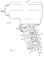
- FIG. 1 there is illustrated a pneumatic impact wrench 10 incorporating a throttle air inlet, generally designated as 12, in accordance with a preferred embodiment of the present invention.
- the pneumatic impact wrench 10 includes a body portion 14 for enclosing a conventional air motor assembly (not shown), and a handle portion 16.
- An air motor assembly is illustrated and described, for example, in the aforementioned U.S. Patent No. 5,544,710.
- the handle portion 16 includes an air inlet channel 18 and an air exhaust channel 20.
- a throttle valve 22 and associated throttle valve seat 24 are biased against a reduced diameter portion 26 of the air inlet channel 18 by a throttle spring 28.
- the throttle valve 22 is actuated in a known manner using a trigger 30 and a throttle pin-push 32.
- a replaceable swivel air inlet bushing 34 is disposed in the lower end of the air inlet channel 18.
- the air inlet bushing 34 includes a threaded fitting 36 for attachment to an air supply hose 38.
- the remaining portion of the air inlet bushing 34 is positioned within the air inlet channel 18.
- the air inlet bushing 34 includes at least one O-ring 40, formed of rubber or other suitable material, for pneumatically sealing the bushing 34 against the inner surface 42 of the air inlet channel 18.
- Each O-ring 40 is seated in a circumferential groove 44 formed about the periphery of the air inlet bushing 34.
- the O-rings 40 pneumatically seal the air inlet bushing 34 within the air inlet channel 18 when the bushing 34 is stationary with respect to the pneumatic impact wrench 10, and, as will be described in greater detail below, during rotation of the bushing 34 within the air inlet channel 18.
- a first end of the throttle spring 28 encircles the head of the throttle valve 22 and engages the throttle valve seat 24.
- a second end of the throttle spring 28 extends into a cup-shaped end 46 of the air inlet bushing 34.
- the throttle spring 28 is maintained in a compressed state to bias the throttle valve seat 24 against the restricted portion 26 of the air inlet channel 18.
- a bore 48 extends from the cup-shaped end 46 to the threaded fitting 36 of the air inlet bushing 34 to provide an air passageway between the air supply hose 38 and the air motor (not shown) via the air inlet channel 18.
- An air screen 50 prevents contaminants from entering the interior of the pneumatic impact wrench 10.
- the air inlet bushing 34 is rotatably disposed within the handle portion 16 of the pneumatic impact wrench 10.
- the rotation of the air inlet bushing 34 is achieved through the use of a pin-roll 52 which is removably inserted through an aperture 54 (see FIG. 2) formed in the handle portion 16 of the pneumatic impact wrench.
- the pin-roll 52 when inserted in the handle portion 16, engages a complementary groove 56 formed around the circumference of the air inlet bushing 34. This arrangement allows the air inlet bushing 34 to freely rotate a full 360 degrees about an axis of rotation 58 within the handle portion 16 of the pneumatic impact wrench 10.
- the pneumatic impact wrench 10 may be rotated about the axis 58 independently of an air supply hose 38 coupled to the air inlet bushing 34.
- the range of rotation of the air inlet bushing 34 can be limited to less than 360 degrees, however, by forming the groove 56 around a portion of the circumference of the bushing 34.
- the air inlet bushing 34 is easily replaced when necessary within the handle portion 16 of the pneumatic impact wrench 10.
- the replacement procedure is illustrated in detail in FIG. 2.
- a user simply removes the pin-roll 52 from the aperture 54 (directional arrow 62), and pulls the air inlet bushing 34 out of the handle portion 16 (directional arrow 64).
- a replacement air inlet bushing 34 can then be inserted into the handle portion 16, and rotatably secured therein, by reinserting the pin-roll 52 into the aperture 54.
- the air inlet bushing 34 further includes a positioning flange 60 for limiting the insertion depth of the bushing 34 within the handle portion 16, to correctly align the aperture 54 with the groove 52.
- the air inlet bushing 34 of the present invention is designed to be used interchangeably in the throttle air inlet of a wide variety of pneumatic tools. As described above, for example, the air inlet bushing 34 can be used to rotatably attach an air supply hose 38 to the handle portion 16 of a pneumatic impact wrench 10. An additional example of a pneumatic tool incorporating the air inlet bushing 34 is shown in FIG. 3, wherein the air inlet bushing 34 is used in the throttle air inlet 70 of a pneumatic ratchet wrench 72.
- the throttle air inlet 70 of the pneumatic ratchet wrench 72 has substantially the same configuration as the throttle air inlet 12 of the previously described pneumatic impact wrench 10.
- the trigger assembly comprising a trigger 74 and a throttle pin-push 76, is specifically designed for use with the pneumatic ratchet wrench 72.
- the pneumatic ratchet wrench 72 includes a handle portion 78 which encloses the throttle air inlet 70, and a body portion 80 which encloses an air motor (not shown).
- the handle portion 78 includes an air inlet channel 82 for passing pressurized air from an attached air inlet hose 38 to the air motor through the air inlet bushing 34.
- the air inlet bushing 34 includes at least one O-ring 40 for pneumatically sealing the bushing 34 against the inner surface 84 of the air inlet channel 82.
- Each O-ring 40 is disposed within a groove 44 which encircles the air inlet bushing 34.
- the O-rings 40 seal the air inlet bushing 34 within the air inlet channel 82 when the bushing 34 is stationary with respect to the pneumatic ratchet wrench 72, and during rotation of the bushing 34 within the air inlet channel 82.
- the air inlet bushing 34 is rotatably secured within the air inlet channel 82 by the coaction of a removable pin-roll 52 and a groove 56 formed on the surface of the bushing 34. This allows the pneumatic ratchet wrench 72 to be rotated along its longitudinal axis independently of an air inlet hose 38 attached to the air inlet bushing 34.
- the pin-roll 52 is removably inserted into the groove 56 of the air inlet bushing 34 through an opening (not shown) in the handle portion 78 of the pneumatic ratchet wrench 72.
- the air inlet bushing 34 can be replaced in a manner similar to that described above with regard to FIG. 2.
- a throttle valve arrangement comprising a throttle valve 22 and a throttle valve seat 24 is positioned for operation by a throttle spring 28.
- a first end of the throttle spring 28 biases the throttle valve assembly against a reduced diameter portion 26 of the air inlet channel 82.
- the opposing end of the throttle spring 28 is positioned within the cup-shaped end 46 of the air inlet bushing 34.
- the throttle valve 22 is actuated as known in the art by the trigger 74 and pin-push 76 combination.
- FIG. 4 A perspective view of the air inlet bushing 34 of the present invention is provided in FIG. 4. This view clearly illustrates the O-ring grooves 44, and the groove 56 which, in conjunction with the pin-roll 52, allow the air inlet bushing 34 to rotate independently of the main body of a pneumatic tool.
Landscapes
- Engineering & Computer Science (AREA)
- Mechanical Engineering (AREA)
- Details Of Spanners, Wrenches, And Screw Drivers And Accessories (AREA)
- Portable Power Tools In General (AREA)
- Finish Polishing, Edge Sharpening, And Grinding By Specific Grinding Devices (AREA)
Applications Claiming Priority (2)
| Application Number | Priority Date | Filing Date | Title |
|---|---|---|---|
| US76830796A | 1996-12-17 | 1996-12-17 | |
| US768307 | 1996-12-17 |
Publications (2)
| Publication Number | Publication Date |
|---|---|
| EP0849052A2 true EP0849052A2 (fr) | 1998-06-24 |
| EP0849052A3 EP0849052A3 (fr) | 1999-07-28 |
Family
ID=25082125
Family Applications (1)
| Application Number | Title | Priority Date | Filing Date |
|---|---|---|---|
| EP97120465A Withdrawn EP0849052A3 (fr) | 1996-12-17 | 1997-11-21 | Papillon d'entrée d'air pour un outil pneumatique |
Country Status (2)
| Country | Link |
|---|---|
| EP (1) | EP0849052A3 (fr) |
| JP (1) | JPH10180652A (fr) |
Cited By (6)
| Publication number | Priority date | Publication date | Assignee | Title |
|---|---|---|---|---|
| WO2001054865A3 (fr) * | 2000-01-27 | 2002-02-14 | S P Air Kk | Outil rotatif pneumatique |
| US6443239B1 (en) | 2000-02-29 | 2002-09-03 | S.P. Air Kabusiki Kaisha | Pneumatic rotary tool |
| WO2003045637A1 (fr) * | 2001-11-26 | 2003-06-05 | Atlas Copco Tools Ab | Outil pneumatique dote d'un deflecteur de l'air d'evacuation |
| US6796386B2 (en) | 2000-09-08 | 2004-09-28 | S.P. Air Kabusiki Kaisha | Pneumatic rotary tool |
| US6880645B2 (en) | 2002-06-14 | 2005-04-19 | S.P. Air Kabusiki Kaisha | Pneumatic rotary tool |
| US7134697B2 (en) * | 2004-08-03 | 2006-11-14 | Basso Industry Corp. | 360° rotatable inlet screw assembly for a pneumatic tool |
Families Citing this family (1)
| Publication number | Priority date | Publication date | Assignee | Title |
|---|---|---|---|---|
| TWI393616B (zh) * | 2011-06-02 | 2013-04-21 | Tranmax Machinery Co Ltd | Used for pneumatic tools |
Family Cites Families (4)
| Publication number | Priority date | Publication date | Assignee | Title |
|---|---|---|---|---|
| US4258799A (en) * | 1979-11-27 | 1981-03-31 | Dresser Industries, Inc. | Inlet control valve |
| US4594030A (en) * | 1984-01-30 | 1986-06-10 | The Boeing Company | Pneumatic-hydraulic drill unit |
| SE460348B (sv) * | 1985-12-23 | 1989-10-02 | Atlas Copco Ab | Pneumatisk mutterdragare med tryckregulator |
| US5197711A (en) * | 1991-07-01 | 1993-03-30 | Ingersoll-Rand Company | Fluid connection and control device for fluid machines |
-
1997
- 1997-11-21 EP EP97120465A patent/EP0849052A3/fr not_active Withdrawn
- 1997-12-12 JP JP9343184A patent/JPH10180652A/ja active Pending
Cited By (8)
| Publication number | Priority date | Publication date | Assignee | Title |
|---|---|---|---|---|
| WO2001054865A3 (fr) * | 2000-01-27 | 2002-02-14 | S P Air Kk | Outil rotatif pneumatique |
| US7404450B2 (en) | 2000-01-27 | 2008-07-29 | S.P. Air Kabusiki Kaisha | Pneumatic rotary tool |
| US6443239B1 (en) | 2000-02-29 | 2002-09-03 | S.P. Air Kabusiki Kaisha | Pneumatic rotary tool |
| US6796386B2 (en) | 2000-09-08 | 2004-09-28 | S.P. Air Kabusiki Kaisha | Pneumatic rotary tool |
| WO2003045637A1 (fr) * | 2001-11-26 | 2003-06-05 | Atlas Copco Tools Ab | Outil pneumatique dote d'un deflecteur de l'air d'evacuation |
| US6923272B2 (en) | 2001-11-26 | 2005-08-02 | Atlas Copco Tools Ab | Pneumatic power tool with exhaust air outlet deflector |
| US6880645B2 (en) | 2002-06-14 | 2005-04-19 | S.P. Air Kabusiki Kaisha | Pneumatic rotary tool |
| US7134697B2 (en) * | 2004-08-03 | 2006-11-14 | Basso Industry Corp. | 360° rotatable inlet screw assembly for a pneumatic tool |
Also Published As
| Publication number | Publication date |
|---|---|
| EP0849052A3 (fr) | 1999-07-28 |
| JPH10180652A (ja) | 1998-07-07 |
Similar Documents
| Publication | Publication Date | Title |
|---|---|---|
| JP4657157B2 (ja) | 排気を調整できる空気式回転駆動手持ち装置 | |
| US6598500B1 (en) | Double-nut tool and method of setting the toe angle of a vehicle wheel | |
| JP3217420U (ja) | ロック機能及び解除機能を備えるトルクスリーブ | |
| US4936701A (en) | Universal joint with rotating holder sleeve | |
| US5855222A (en) | Multi-purpose pneumatic tool | |
| US5741084A (en) | Wear compensating axial connection | |
| US9278439B1 (en) | Valve core gripper device | |
| US6152165A (en) | Valve core mounting and dismounting tool | |
| PL182707B1 (pl) | Końcówka do nadmuchiwania opon pojazdów | |
| RU97112091A (ru) | Блокирующийся многоцелевой пневматический инструмент | |
| EP0849052A2 (fr) | Papillon d'entrée d'air pour un outil pneumatique | |
| US7083003B1 (en) | Power tool with detachable drive end | |
| US5197711A (en) | Fluid connection and control device for fluid machines | |
| US8214986B2 (en) | Valve stem puller | |
| US4903944A (en) | Valve assembly and method | |
| EP1033205A2 (fr) | Outil pour installer ou démonter des noyaux de valve | |
| GB1599304A (en) | Inflation valve connectors | |
| US7178549B2 (en) | Valve coupling device for pump | |
| US6145161A (en) | Multifunctional dust-abating gun | |
| CN218050352U (zh) | 拉刀结构 | |
| EP0406203A2 (fr) | Raccord rapide du type soupape rotative | |
| KR100316966B1 (ko) | 바이어스된 칼라 밸브 액추에이터를 구비하는 인장 공구및 그를 위한 방법 | |
| JP2001225729A (ja) | タイヤ用気体充填装置 | |
| US4756686A (en) | Torch handle with locking valve | |
| JP3253254U (ja) | エアチャックおよびエアチャック用のヘッド |
Legal Events
| Date | Code | Title | Description |
|---|---|---|---|
| PUAI | Public reference made under article 153(3) epc to a published international application that has entered the european phase |
Free format text: ORIGINAL CODE: 0009012 |
|
| AK | Designated contracting states |
Kind code of ref document: A2 Designated state(s): AT BE CH DE DK ES FI FR GB GR IE IT LI LU MC NL PT SE |
|
| AX | Request for extension of the european patent |
Free format text: AL;LT;LV;MK;RO;SI |
|
| PUAL | Search report despatched |
Free format text: ORIGINAL CODE: 0009013 |
|
| RIC1 | Information provided on ipc code assigned before grant |
Free format text: 6B 25F 5/00 A, 6F 16L 37/14 B |
|
| AK | Designated contracting states |
Kind code of ref document: A3 Designated state(s): AT BE CH DE DK ES FI FR GB GR IE IT LI LU MC NL PT SE |
|
| AX | Request for extension of the european patent |
Free format text: AL;LT;LV;MK;RO;SI |
|
| AKX | Designation fees paid | ||
| REG | Reference to a national code |
Ref country code: DE Ref legal event code: 8566 |
|
| STAA | Information on the status of an ep patent application or granted ep patent |
Free format text: STATUS: THE APPLICATION IS DEEMED TO BE WITHDRAWN |
|
| 18D | Application deemed to be withdrawn |
Effective date: 20000129 |