EP0849057B1 - Procédé et dispositif pour l'usinage de surface d'articles allongés - Google Patents
Procédé et dispositif pour l'usinage de surface d'articles allongés Download PDFInfo
- Publication number
- EP0849057B1 EP0849057B1 EP97121806A EP97121806A EP0849057B1 EP 0849057 B1 EP0849057 B1 EP 0849057B1 EP 97121806 A EP97121806 A EP 97121806A EP 97121806 A EP97121806 A EP 97121806A EP 0849057 B1 EP0849057 B1 EP 0849057B1
- Authority
- EP
- European Patent Office
- Prior art keywords
- machine according
- conveyor
- pairs
- brushes
- rotary brushes
- Prior art date
- Legal status (The legal status is an assumption and is not a legal conclusion. Google has not performed a legal analysis and makes no representation as to the accuracy of the status listed.)
- Expired - Lifetime
Links
- 238000000034 method Methods 0.000 title claims description 5
- 238000004381 surface treatment Methods 0.000 title claims description 5
- 238000012545 processing Methods 0.000 claims description 16
- 238000012856 packing Methods 0.000 claims description 3
- 238000000605 extraction Methods 0.000 claims description 2
- 239000006260 foam Substances 0.000 claims description 2
- 239000002699 waste material Substances 0.000 claims 2
- 230000008878 coupling Effects 0.000 claims 1
- 238000010168 coupling process Methods 0.000 claims 1
- 238000005859 coupling reaction Methods 0.000 claims 1
- 239000000463 material Substances 0.000 description 7
- 230000006378 damage Effects 0.000 description 6
- 238000003754 machining Methods 0.000 description 5
- 239000000428 dust Substances 0.000 description 3
- 208000027418 Wounds and injury Diseases 0.000 description 2
- 238000005299 abrasion Methods 0.000 description 2
- 238000004140 cleaning Methods 0.000 description 2
- 238000011161 development Methods 0.000 description 2
- 208000014674 injury Diseases 0.000 description 2
- 238000012544 monitoring process Methods 0.000 description 2
- 230000003287 optical effect Effects 0.000 description 2
- 206010010774 Constipation Diseases 0.000 description 1
- 241000196324 Embryophyta Species 0.000 description 1
- 240000007594 Oryza sativa Species 0.000 description 1
- 235000007164 Oryza sativa Nutrition 0.000 description 1
- 235000009754 Vitis X bourquina Nutrition 0.000 description 1
- 235000012333 Vitis X labruscana Nutrition 0.000 description 1
- 240000006365 Vitis vinifera Species 0.000 description 1
- 235000014787 Vitis vinifera Nutrition 0.000 description 1
- 230000001070 adhesive effect Effects 0.000 description 1
- 230000034303 cell budding Effects 0.000 description 1
- 238000010276 construction Methods 0.000 description 1
- 230000007423 decrease Effects 0.000 description 1
- 230000000694 effects Effects 0.000 description 1
- 230000007717 exclusion Effects 0.000 description 1
- 239000000835 fiber Substances 0.000 description 1
- 238000007730 finishing process Methods 0.000 description 1
- 238000000227 grinding Methods 0.000 description 1
- 238000003780 insertion Methods 0.000 description 1
- 230000037431 insertion Effects 0.000 description 1
- 239000010985 leather Substances 0.000 description 1
- 238000003801 milling Methods 0.000 description 1
- 238000005498 polishing Methods 0.000 description 1
- 235000009566 rice Nutrition 0.000 description 1
- 238000000926 separation method Methods 0.000 description 1
- 239000007858 starting material Substances 0.000 description 1
- 238000011144 upstream manufacturing Methods 0.000 description 1
- 230000000007 visual effect Effects 0.000 description 1
- 239000002023 wood Substances 0.000 description 1
- 230000003245 working effect Effects 0.000 description 1
Images

Classifications
-
- A—HUMAN NECESSITIES
- A01—AGRICULTURE; FORESTRY; ANIMAL HUSBANDRY; HUNTING; TRAPPING; FISHING
- A01G—HORTICULTURE; CULTIVATION OF VEGETABLES, FLOWERS, RICE, FRUIT, VINES, HOPS OR SEAWEED; FORESTRY; WATERING
- A01G17/00—Cultivation of hops, vines, fruit trees, or like trees
- A01G17/02—Cultivation of hops or vines
-
- A—HUMAN NECESSITIES
- A01—AGRICULTURE; FORESTRY; ANIMAL HUSBANDRY; HUNTING; TRAPPING; FISHING
- A01G—HORTICULTURE; CULTIVATION OF VEGETABLES, FLOWERS, RICE, FRUIT, VINES, HOPS OR SEAWEED; FORESTRY; WATERING
- A01G17/00—Cultivation of hops, vines, fruit trees, or like trees
- A01G17/02—Cultivation of hops or vines
- A01G17/023—Machines for priming and/or preliminary pruning of vines, i.e. removing shoots and/or buds
-
- A—HUMAN NECESSITIES
- A01—AGRICULTURE; FORESTRY; ANIMAL HUSBANDRY; HUNTING; TRAPPING; FISHING
- A01G—HORTICULTURE; CULTIVATION OF VEGETABLES, FLOWERS, RICE, FRUIT, VINES, HOPS OR SEAWEED; FORESTRY; WATERING
- A01G3/00—Cutting implements specially adapted for horticultural purposes; Delimbing standing trees
- A01G2003/005—Removing buds
-
- A—HUMAN NECESSITIES
- A01—AGRICULTURE; FORESTRY; ANIMAL HUSBANDRY; HUNTING; TRAPPING; FISHING
- A01G—HORTICULTURE; CULTIVATION OF VEGETABLES, FLOWERS, RICE, FRUIT, VINES, HOPS OR SEAWEED; FORESTRY; WATERING
- A01G5/00—Floral handling
- A01G2005/005—Thorn removers
Definitions
- the invention relates to a machine for Surface treatment of elongated objects, which Have buds, especially vine shoots, after Preamble of claim 1 and a method for Removal of buds from root shoots.
- a noble rice is placed on one Grafted a so-called rootstock.
- the so formed young plant forms roots at its free end, and the grafted noble grape variety shoots out, the Underlay itself should not have any buds. This as Eyes labeled buds on the pad need to be removed what is called aperture.
- the buds of the underlay sit in niches above the knot and are usually removed by hand.
- Processing of vine shoots with one machine according to the preamble of claim 1 and claim 25 is from FR 2 536 693 A1 known. This works by means of rotating knives or Saws that cut tangentially to the surface of the shoot. There is an increased risk of removing buds damage to the pad at the knots, the protrude irregularly from the surface. Avoid that Damage to the nodes, it often happens that individual Buds of the dossier do not capture what to subsequent manual work forces.
- the processing of vine shoots with one Circular cut is known from FR 2 498 417.
- the tool consists of a tubular milling machine or saw with which striving side branches are cut off, buds however, those who sit in niches of wood are not removed can be.
- the invention has for its object a Machine or a method for surface treatment of to create elongated, budding objects, with the unwanted buds, especially from vine shoots, on material-saving, efficient and easy to monitor Way can be removed and also other elongated objects undergo cleaning or surface treatment can
- the task is based on the characteristics of the Claim 1 and 25 solved and by the other features of the subclaims designed and developed.
- the elongated objects with conveyor modules by one or more Rotary brush pairs are encouraged, and the brushes are like that designed to "erase” the buds of the vine shoots, without damaging the bark and the wooden body.
- the Brushes, their speed of rotation and the Throughput speed of the elongated objects adapted to the special material to be processed. this applies also for the distance between the brushes.
- the Workflow can be done largely automatically, d. H. without special requirements for the operating personnel.
- the shoots are also removed from adhering earth, mud and the like cleaned.
- the machine is modular and includes expediently several funding modules and Rotary brush pairs.
- the rotary brushes will be expediently around the circumference of the elongated objects distributed to the whole to be processed Detect surface with the same intensity, d. H. in the In case of vine rootstocks remove all buds.
- the Conveyor modules are adjustable and designed so that it is too a continuous feed rate of processing elongated objects. This can cause the thickness of the objects to fluctuate be compensated for that elastic on the conveyor rollers Rubber slats are attached to the gap between the Make conveyor rollers variable. Conveyor rollers can also be used or rolls with foam pads on the surface can be used with which also the underlay drives can be advanced largely without slippage.
- the action of the rotary brushes depends on that Brush material and the distance of the brushes from the Pass axis from.
- the distance of the brushes from the pass axis can be set.
- individual brushes can be used can also be replaced by grinding or polishing discs.
- an automatic feeder for elongated objects upstream and a counter assigned for processed objects In case of Vine shoots can also have a cutting device and a Packing device for processed shoots Processing machine downstream.
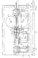
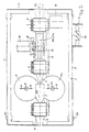
- the main components of the Document processing machine are a frame 3, three Conveyor modules 4 and four rotary brushes 20, 20a, 21, 21a in two pairs.
- an imaginary axis 32 runs on which the drives 1 go through the machine.
- the shoots to be processed 1 have at certain intervals (so-called internodes), which depend on Variety vary, node 2, at which the to be brushed off Sitting buds (eyes).
- the pairs of rotary brushes 20 / 20a and 21 / 21a are rotated by 90 ° to each other between two Conveyor modules 4 arranged.
- the mutual arrangement of the Brush and conveyor modules ensure a uniform Machining along the entire length of the shoot, in particular also in the area of the ends.
- the number of pairs of rotating brushes used and Funding modules can be varied.
- a single conveyor module 4 with a single pair of rotary brushes 20 / 20a can be combined.
- Rotary brush pairs can be used.
- the respective Angular position of the pairs of brushes to each other and around Pass axis 32 decreases with a higher number of used pairs of rotary brushes, with which the scope of the Shoots are processed evenly.
- the individual rotary brushes 20 + 20a and 21 + 21a are each via a shaft or hub 25, 25a Motor 26 in the same or opposite direction to the conveying direction of the drive 1 driven.
- the distance between the individual brushes 21 + 21a and 20 + 20a or the Machining gap can be varied, allowing for each processing material an optimal drive passage width and Machining intensity can be achieved.
- the brush hubs are 25, 25a each mounted on separate sliding plates 27, which in a linear guide 26 against or away from each other can be moved and set in the set positions.
- the associated spindle nuts with left and right hand threads each sit on one of the two sliding plates 27.
- Through Rotating the spindle by means of handwheel 28 moves the Brush hubs simultaneously in direction 23 from axis 32 away or in the direction 24 towards it, causing the continuous Drive 2 a larger or smaller machining gap finds. This can cause the abrasion effect of the Rotation brushes are reduced or reinforced.
- the Speed of the motors 26 is varied, the Working effect of the rotary brushes also affected become.
- the Rotation brushes 20, 20a, 21, 21a each have several thin ones Element disks 22, which together to a thicker Rotary brush can be assembled together.
- the element construction has the advantage that the inner, near the axis 32nd working and rather worn elements 22 with the less worn outer element disks exchanged can be, reducing the life of the rotary brush is extended overall.
- the bristle material of Rotary brushes come in different materials and Dimensions into consideration.
- FIGS. 3 and 4 included the conveyor modules 4, a housing 38, wherein in the transverse direction Drive axis 32 each have two shafts or axes 9, 9a, in Ball bearings 10 in stock, are arranged.
- the funding modules 4 are mounted on holders 8 (Fig. 1), which in turn on Frame 3 are attached.
- the shafts or axes 9 and 9a together form one Conveyor axis pair. They are mutually engaged over two located gears 12 coupled to each other, whereby a from the belt gear 11 rotary movement without slip from Axis 9 on the partner axis 9a, which is a receives counter-rotating movement, is transmitted.
- On the Axles 9, 9a are coupled with a respective conveyor roller 14 with elastic slats 14a.
- the fins 14a are radial arranged to the conveyor roller 14, but it is also a axial arrangement possible.
- Belt wheels 11 are by means of a motor 16 (Fig. 2) and a toothed belt 15 driven.
- the timing belt 15 wraps around the belt wheels 11, a plurality of deflection rollers 17, one Tension roller 18 and a motor drive wheel 37 in the in Fig. 1st drawn type, whereby all of the conveyor module axes 9 receive identical direction of rotation and speed.
- the elastic slats 14a and Roller body 14 ensure secure adhesion and a largely slip-free propulsion of the drive 1 under Exclusion of any risk of injury and crushing for the Shoots 1.
- the embodiment of this type also has the Advantage that shoots of different calibres, Regular growth and internode length are promoted can without any adjustments.
- the Motor 16 for driving the toothed belt 15 a continuously variable speed control, with which the drives 1 desired throughput speed can be issued.
- each has Delivery module 4 each have an inlet funnel 5 or Connection funnel 7 and an outlet funnel 6.
- the Inlet and outlet openings are dimensioned so that that shoots of different calibers on the one hand from the predetermined pass axis 32 do not deviate laterally can, and on the other hand from the rotary brushes to be recorded correctly.
- the conveyor modules 4 have a bottom Opening 13 so that the dirt, buds and Fiber parts can fall out. That’s why Conveyor modules 4 self-cleaning and against constipation protected.
- the machine frame 3 is on its underside open, so that the brushed material directly through a Opening 34 in table 33 falls where it can be disposed of.
- the frame 3 In order to eliminate the risk of injury and as Protection against the development of dust is the frame 3 on all accessible sides with covers 31.
- the covers are preferably made of one machine clear material made.
- In one embodiment of the invention is outside or lighting is installed within the frame 3, which facilitates optical monitoring.
- the machine is open to absorb vibrations Rubber elements 36 stored.
- an automatic drive cutting device not shown intended. This works e.g. B. such that the shoots 1 run against a stop and then press one Trigger scissors or a drop knife, which the rear Cuts off the end of the shoot. The drive then falls into one Container, whereby it can be counted.
- automatic loading device for unprocessed shoots 1 arranged.
- the Loading device removes the shoots 1 individually a camp and pushes the isolated shoot into the Funnel 5 of the processing machine.
- the camp can be one have funnel-shaped constriction in which a Separating shaft with pockets for the shoots is arranged, by rotating the clock Separation wave each time a drive from the warehouse can be removed.
Landscapes
- Life Sciences & Earth Sciences (AREA)
- Botany (AREA)
- Environmental Sciences (AREA)
- Apparatuses For Bulk Treatment Of Fruits And Vegetables And Apparatuses For Preparing Feeds (AREA)
- Catching Or Destruction (AREA)
- Treatment Of Fiber Materials (AREA)
- Finish Polishing, Edge Sharpening, And Grinding By Specific Grinding Devices (AREA)
Claims (25)
- Machine pour le traitement de surface d'objets allongés qui présentent des bourgeons, en particulier des rameaux de vigne, possédant les caractéristiques suivantes :caractérisée en ce que l'outil comprend au moins deux brosses (20, 20a) qui forment entre elles une fente de traitement qui est disposée le long de l'axe de passage (32), les brosses frottant avec effet de gommage le long de l'objet allongé (1) et les bourgeons étant ainsi éliminés.une charpente de bâti (3) qui détermine un axe de passage (32) ;au moins un module de transport (4) qui renferme au moins une paire de tambours de transport (14) qui forme une fente de transport entre eux et est agencée pour placer cette fente le long de l'axe de passage (32);au moins un outil qui traite l'objet allongé, qui circule le long de l'axe de passage,
- Machine selon la revendication 1,
caractérisée en ce qu'il est prévu deux ou plus de deux modules de transport (4). - Machine selon la revendication 1 ou 2,
caractérisée en ce qu'il est prévu deux ou plus de deux paires de brosses rotatives (20, 20a ; 21, 21a). - Machine selon la revendication 3,
caractérisée en ce que les paires de brosses rotatives (20, 20a ; 21, 21a) sont disposées de façon décalées angulairement par rapport à l'axe de passage (32). - Machine selon la revendication 3,
caractérisée en ce que des entonnoirs d'entrée, de liaison et de sortie (5, 6, 7) sont prévus entre les paires des brosses rotatives (20, 20a ; 21, 21a) et les modules de transport (4 ). - Machine selon une des revendications 1 à 5,
caractérisée en ce que la fente de traitement entre les brosses rotatives de la paire ou des paires de brosses rotatives peut être réglée grâce à l'interchangeabilité des brosses (20, 20a ; 21, 21a). - Machine selon une des revendications 1 à 6,
caractérisée en ce que la distance à l'axe des paires de brosses rotatives est réglable. - Machine selon une des revendications 1 à 7,
caractérisée en ce que les paires de brosses rotatives (20, 20a ; 21, 21a) présentent des disques élémentaires interchangeables (22). - Machine selon une des revendications 1 à 8,
caractérisée en ce que chaque paire de brosses rotatives représente un entraínement individuel (25, 26). - Machine selon la revendication 9,
caractérisée en ce que l'entraínement individuel (25, 26) est réglable en vitesse de rotation et en sens de rotation. - Machine selon une dès revendications 1 à 8,
caractérisée en ce que les paires de brosses rotatives présentent un entraínement commun. - Machine selon une des revendications 1 à 11,
caractérisée en ce que les modules de transport (4) présentent un entraínement commun réalisé au moyen de courroies crantées (15), de chaínes ou d'éléments d'accouplement sans fin analogues. - Machine selon une des revendications 1 à 12,
caractérisée en ce que les tambours de transport (14) d'un module de transport (4) sont accouplés entre eux par des roues dentées (12). - Machine selon une des revendications 1 à 13,
caractérisée en ce que les tambours de transport (14) des modules de tambours de transport (4) sont équipés de lamelles élastiques (14a). - Machine selon une des revendications 1 à 14,
caractérisée en ce que les tambours de transport (14) des modules de tambours de transport (4) sont équipés de coussins en mousse. - Machine selon une des revendications 1 à 15,
caractérisée en ce que l'entraínement des tambours de transport (14) est réglable pour obtenir différentes vitesses. - Machine selon une des revendications 1 à 16,
caractérisée en ce que chaque module de transport (4) présente un carter (38) muni d'une ouverture de sortie (13) pour les déchets. - Machine selon une des revendications 1 à 17,
caractérisée en ce que la charpente de bâti (3) présente une ouverture (34) de sortie de déchets. - Machine selon une des revendications 1 à 18,
caractérisée en ce que la charpente de bâti (3) présente un dispositif d'aspiration (29, 30). - Machine selon une des revendications 1 à 19,
caractérisée par un dispositif d'éclairage. - Machine selon une des revendications 1 à 20,
caractérisée par un dispositif de coupe à longueur qui coupe les objets allongés (1) traités en morceaux d'une longueur prédéterminée lorsqu'ils ont quitté l'étage de traitement. - Machine selon une des revendications 1 à 21,
caractérisée par un dispositif compteur qui compte les objets allongés (1) traités. - Machine selon une des revendications 1 à 22,
caractérisée par un dispositif de chargement automatique pour les objets allongés non traités, qui prélève ces objets individuellement dans un magasin et les introduit dans l'étage de traitement. - Machine selon une des revendications 1 à 15,
caractérisée par un dispositif d'empaquetage automatique pour les objets traités, qui place un enveloppement autour des objets. - Procédé pour l'élimination des bourgeons de rameaux sujets à améliorer, en particulier de vigne, comprenant l'étape suivante :a) les rameaux sujets (1) sont placés l'un après l'autre dans la fente de paires de tambour de transport (14) qui poussent les rameaux sujets (1) le long d'un axe de passage (32) ; et l'étape caractéristique :b) des brosses rotatives (20, 20a) disposées le long de l'axe de passage (32) enlèvent les bourgeons (2) du rameau sujet (1) transporté.
Priority Applications (1)
| Application Number | Priority Date | Filing Date | Title |
|---|---|---|---|
| SI9730137T SI0849057T1 (en) | 1996-12-17 | 1997-12-11 | Apparatus and method for surface treatment of elongated articles |
Applications Claiming Priority (2)
| Application Number | Priority Date | Filing Date | Title |
|---|---|---|---|
| DE19652510A DE19652510C2 (de) | 1996-12-17 | 1996-12-17 | Maschine und Verfahren zur Oberflächenbearbeitung von länglichen Gegenständen |
| DE19652510 | 1996-12-17 |
Publications (3)
| Publication Number | Publication Date |
|---|---|
| EP0849057A2 EP0849057A2 (fr) | 1998-06-24 |
| EP0849057A3 EP0849057A3 (fr) | 2000-04-26 |
| EP0849057B1 true EP0849057B1 (fr) | 2001-10-04 |
Family
ID=7815023
Family Applications (1)
| Application Number | Title | Priority Date | Filing Date |
|---|---|---|---|
| EP97121806A Expired - Lifetime EP0849057B1 (fr) | 1996-12-17 | 1997-12-11 | Procédé et dispositif pour l'usinage de surface d'articles allongés |
Country Status (9)
| Country | Link |
|---|---|
| US (1) | US6016626A (fr) |
| EP (1) | EP0849057B1 (fr) |
| CA (1) | CA2225134C (fr) |
| CZ (1) | CZ292234B6 (fr) |
| DE (1) | DE19652510C2 (fr) |
| ES (1) | ES2162184T3 (fr) |
| HU (1) | HU222448B1 (fr) |
| PT (1) | PT849057E (fr) |
| SI (1) | SI0849057T1 (fr) |
Families Citing this family (11)
| Publication number | Priority date | Publication date | Assignee | Title |
|---|---|---|---|---|
| MXJL03000021A (es) * | 2003-08-01 | 2005-02-03 | Ct De Investigacion Y Asistenc | Desespinadora de nopales compacta auto ajustable. |
| ITMI20041641A1 (it) * | 2004-08-10 | 2004-11-10 | Olimpia 80 Srl | Impianto di satinatura a ruote lamellari per tubi sagomati |
| US10231388B2 (en) | 2015-04-30 | 2019-03-19 | Hibervine Llc | Appartus for protecting cold sensitive scions |
| US9687017B1 (en) | 2015-09-16 | 2017-06-27 | Adrian C. Cabrera | Cactus processing system |
| US10512219B2 (en) * | 2016-08-31 | 2019-12-24 | Cullen Raichart | Rotary plant stripper and related methods |
| US10807098B1 (en) | 2017-07-26 | 2020-10-20 | Pearson Incorporated | Systems and methods for step grinding |
| US10751722B1 (en) | 2018-10-24 | 2020-08-25 | Pearson Incorporated | System for processing cannabis crop materials |
| US10785906B2 (en) | 2019-02-19 | 2020-09-29 | Pearson Incorporated | Plant processing system |
| US10524423B1 (en) | 2019-02-19 | 2020-01-07 | Hemp Processing Solutions, LLC | Plant processing system |
| US10757860B1 (en) | 2019-10-31 | 2020-09-01 | Hemp Processing Solutions, LLC | Stripper apparatus crop harvesting system |
| US10933424B1 (en) | 2019-12-11 | 2021-03-02 | Pearson Incorporated | Grinding roll improvements |
Family Cites Families (37)
| Publication number | Priority date | Publication date | Assignee | Title |
|---|---|---|---|---|
| US887519A (en) * | 1907-01-03 | 1908-05-12 | Homer L Reed | Machine for stripping leaves from trees. |
| FR374063A (fr) * | 1907-01-29 | 1907-06-04 | Hans Hochmuth | Fixation du manche pour instruments de tous genres |
| US1390218A (en) * | 1920-05-01 | 1921-09-06 | Sauset Peter | Machine for cleaning builders' planks from cement |
| US2611215A (en) * | 1946-12-14 | 1952-09-23 | Johnson Co Gordon | Leaf stripper |
| US2592833A (en) * | 1947-01-20 | 1952-04-15 | Barker Poultry Equipment Compa | Apparatus for stripping leaves from flowers |
| US2588903A (en) * | 1947-01-23 | 1952-03-11 | Alfred A Dorman | Log peeling and shaping apparatus |
| US2710417A (en) * | 1951-03-21 | 1955-06-14 | Byron W Short | Lumber reconditioning device |
| US2800934A (en) * | 1952-08-05 | 1957-07-30 | Hosmer Windsor Arnold | Bark-removing apparatus having barkimpacting hammers |
| US2907151A (en) * | 1954-01-18 | 1959-10-06 | Osborn Mfg Co | Conditioning metal sheets, strip, rod and the like |
| US2848841A (en) * | 1957-02-05 | 1958-08-26 | Goodrich Co B F | Tool for use in tree girdling and grafting |
| US2865135A (en) * | 1957-03-18 | 1958-12-23 | Walter J Gamboni | Grape leaf stripping mechanism |
| DE1180115B (de) * | 1958-12-22 | 1964-10-22 | Sunds Verkstaeder Aktiebolag | Anordnung an Entrindungsmaschinen |
| US3189067A (en) * | 1961-06-16 | 1965-06-15 | Soderhamn Machine Mfg Company | Vacuum operated debarking apparatus |
| FR1568591A (fr) * | 1967-06-19 | 1969-05-23 | ||
| US3680255A (en) * | 1970-12-17 | 1972-08-01 | Dmz Anton Ivanov | Grafting machine for seedling material |
| US3913644A (en) * | 1973-04-21 | 1975-10-21 | Braun Kg Maschf | Debarking machine |
| SE7309398L (fr) * | 1973-07-04 | 1975-01-07 | Kockums Ind Ab | |
| DE7533447U (de) * | 1975-10-21 | 1976-03-04 | 7056 Weinstadt | Vorrichtung zum veredeln von pflanzen, insbesondere von weinreben |
| FR2498417A1 (fr) * | 1976-05-06 | 1982-07-30 | Soterem Sa | Machine pour elaguer et sectionner des bois |
| FR2379245A1 (fr) * | 1977-02-03 | 1978-09-01 | Braun Stefan | Dispositif pour enlever les jeunes pousses dans le bas des troncs des vignes |
| IL51940A (en) * | 1977-04-25 | 1978-06-15 | Mashteloth A L B M | Method of propagating roses rapidly by grafting and means therefor |
| FR2408296A1 (fr) * | 1977-11-09 | 1979-06-08 | Nedellec Yves | Amelioration du systeme d'entrainement d'une machine a nettoyer les tiges de fleurs coupees |
| FR2536693A1 (fr) * | 1982-11-25 | 1984-06-01 | Bouteille Paul Frederic | Machine pour nettoyer les bois de multiplication vegetative |
| BG38342A1 (en) * | 1983-06-15 | 1985-12-16 | Peev | Machine for vine engrafting |
| DE3546445A1 (de) * | 1985-01-30 | 1986-09-04 | Armin 6530 Bingen Pieroth | Vorrichtung zum vorschnitt von rebholz an weinstoecken in drahtrahmenanlagen mit kordonerziehung |
| IT1201279B (it) * | 1985-04-19 | 1989-01-27 | Riccardo Tamburini | Spollonatrice per filari di viti e altre culture,con rotore ad asse orizzontale e filamenti radiali |
| FR2613581B1 (fr) * | 1987-04-08 | 1990-12-14 | Grp Champenois Expl Vitic | Procede de production de plants greffes de vegetaux ligneux ou semi-ligneux pour l'obtention de plants, notamment de vigne, et plants obtenus |
| IT1211705B (it) * | 1987-08-10 | 1989-11-03 | Patrucco Sergio | Procedimento di moltiplicazione di varieta' vegetali, e prodotti cosi'ottenuti |
| CA1286596C (fr) * | 1988-01-26 | 1991-07-23 | Willie B. Dueck | Dispositif pour derouler et rebobiner des couvre-plancher |
| US4839986A (en) * | 1988-03-18 | 1989-06-20 | Grantham Debs E | Grafting apparatus |
| FR2641490B1 (fr) * | 1988-12-16 | 1992-03-27 | Durand International | Procede de coupe automatique en troncons d'un corps-mere, notamment de sarments de vigne, et machine de coupe |
| NL8900392A (nl) * | 1989-02-17 | 1990-09-17 | Rober Hermanus Wilhelmus Koend | Werkwijze voor het ontbladeren van plantenstelen en daarvoor bestemde inrichting. |
| FR2648670B1 (fr) * | 1989-06-26 | 1991-10-18 | Leotronic | Dispositif destine a decouper des tiges vegetales pleines en vue de produire des boutures |
| FR2684842B1 (fr) * | 1991-12-13 | 1994-04-08 | Bernard Maynadier | Procede d'ebourgeonnage de sarments de vigne mere et une installation pour sa mise en óoeuvre. |
| US5293714A (en) * | 1992-05-04 | 1994-03-15 | Bouchard Brian L | Method and apparatus for cleaning sod |
| US5651212A (en) * | 1996-07-02 | 1997-07-29 | Jensen; Ann F. | Stripping thorns from rose stems |
| US5704409A (en) * | 1996-09-23 | 1998-01-06 | Denis Comact Chicoutimi Inc. | Flexible mounting system for log debarking equipment |
-
1996
- 1996-12-17 DE DE19652510A patent/DE19652510C2/de not_active Expired - Fee Related
-
1997
- 1997-12-11 PT PT97121806T patent/PT849057E/pt unknown
- 1997-12-11 ES ES97121806T patent/ES2162184T3/es not_active Expired - Lifetime
- 1997-12-11 EP EP97121806A patent/EP0849057B1/fr not_active Expired - Lifetime
- 1997-12-11 SI SI9730137T patent/SI0849057T1/xx unknown
- 1997-12-15 CZ CZ19974028A patent/CZ292234B6/cs not_active IP Right Cessation
- 1997-12-17 US US08/992,776 patent/US6016626A/en not_active Expired - Fee Related
- 1997-12-17 HU HU9702487A patent/HU222448B1/hu not_active IP Right Cessation
- 1997-12-17 CA CA002225134A patent/CA2225134C/fr not_active Expired - Fee Related
Also Published As
| Publication number | Publication date |
|---|---|
| HU9702487D0 (en) | 1998-03-02 |
| CZ402897A3 (cs) | 1998-07-15 |
| HUP9702487A2 (hu) | 1999-02-01 |
| PT849057E (pt) | 2002-01-30 |
| ES2162184T3 (es) | 2001-12-16 |
| CA2225134C (fr) | 2006-05-23 |
| DE19652510A1 (de) | 1998-06-18 |
| CA2225134A1 (fr) | 1998-06-17 |
| HU222448B1 (hu) | 2003-07-28 |
| US6016626A (en) | 2000-01-25 |
| HUP9702487A3 (en) | 2000-08-28 |
| EP0849057A3 (fr) | 2000-04-26 |
| EP0849057A2 (fr) | 1998-06-24 |
| SI0849057T1 (en) | 2001-12-31 |
| DE19652510C2 (de) | 2003-06-12 |
| CZ292234B6 (cs) | 2003-08-13 |
Similar Documents
| Publication | Publication Date | Title |
|---|---|---|
| DE3873548T2 (de) | Vorrichtung zum schaelen von zwiebelgewaechsen. | |
| DE19652510C2 (de) | Maschine und Verfahren zur Oberflächenbearbeitung von länglichen Gegenständen | |
| DE3317276A1 (de) | Zuckerrohr-erntemaschine | |
| DE202015005648U1 (de) | Mäh- und Fördergerät zum Ernten von stängeligem Erntegut | |
| DE3601187A1 (de) | Verfahren und vorrichtung zum binden von bloecken | |
| EP0229752A2 (fr) | Tambour rotatif pour produire des copeaux de bois | |
| EP0727154B1 (fr) | Appareil et procédé pour enlever des corps étrangers à longues fibres du tabac | |
| DE4240805C2 (de) | Kohlerntemaschine | |
| DE102015010222A1 (de) | Mäh- und Fördergerät zum Ernten von stängeligem Erntegut | |
| DE4332430C2 (de) | Mähmaschine, insbesondere Rasenmäher | |
| EP0199726B1 (fr) | Installation d'arrachage de tubercules | |
| DE342443C (de) | Spargelschaelmaschine | |
| DE704089C (de) | Vorrichtung zum Zerschneiden von Hanfstengeln | |
| DE1482199A1 (de) | Erntemaschine,insbesondere Maehdrescher | |
| DE3527841C2 (fr) | ||
| DE363501C (de) | Schwingmaschine | |
| DE503553C (de) | Selbsttaetige Schleifmaschine zum Schaerfen abmontierter Blaetter von Maehmaschinenmessern u. dgl. | |
| DE3805393C1 (en) | Apparatus for the dry cleaning of grains, granular material and the like | |
| DE733175C (de) | Vorrichtung zum Entfernen der Samen von Bastfaserstengeln | |
| EP1008427B1 (fr) | Déchiqueteuse | |
| DE125867C (fr) | ||
| DE69218887T2 (de) | Mähmaschine mit einem Rotor, welcher das geschnittene Gut insbesondere zu den Trägern der Schneidorgane bringt | |
| DE2193C (de) | Gras- und Getreide-Handmähemaschine mit rotirenden Messerscheiben | |
| DE290106C (fr) | ||
| DE80013C (fr) |
Legal Events
| Date | Code | Title | Description |
|---|---|---|---|
| PUAI | Public reference made under article 153(3) epc to a published international application that has entered the european phase |
Free format text: ORIGINAL CODE: 0009012 |
|
| AK | Designated contracting states |
Kind code of ref document: A2 Designated state(s): ES FR IT PT |
|
| AX | Request for extension of the european patent |
Free format text: AL;LT;LV;MK;RO;SI |
|
| PUAL | Search report despatched |
Free format text: ORIGINAL CODE: 0009013 |
|
| 17P | Request for examination filed |
Effective date: 20000301 |
|
| AK | Designated contracting states |
Kind code of ref document: A3 Designated state(s): AT BE CH DE DK ES FI FR GB GR IE IT LI LU MC NL PT SE |
|
| AX | Request for extension of the european patent |
Free format text: AL;LT;LV;MK;RO;SI PAYMENT 20000301 |
|
| RIC1 | Information provided on ipc code assigned before grant |
Free format text: 7A 01G 17/02 A, 7A 01G 1/06 B |
|
| 17Q | First examination report despatched |
Effective date: 20000605 |
|
| GRAG | Despatch of communication of intention to grant |
Free format text: ORIGINAL CODE: EPIDOS AGRA |
|
| AKX | Designation fees paid |
Free format text: ES FR IT PT |
|
| AXX | Extension fees paid |
Free format text: SI PAYMENT 20000301 |
|
| REG | Reference to a national code |
Ref country code: DE Ref legal event code: 8566 |
|
| GRAG | Despatch of communication of intention to grant |
Free format text: ORIGINAL CODE: EPIDOS AGRA |
|
| GRAH | Despatch of communication of intention to grant a patent |
Free format text: ORIGINAL CODE: EPIDOS IGRA |
|
| ITF | It: translation for a ep patent filed | ||
| GRAH | Despatch of communication of intention to grant a patent |
Free format text: ORIGINAL CODE: EPIDOS IGRA |
|
| GRAA | (expected) grant |
Free format text: ORIGINAL CODE: 0009210 |
|
| AK | Designated contracting states |
Kind code of ref document: B1 Designated state(s): ES FR IT PT |
|
| AX | Request for extension of the european patent |
Free format text: SI PAYMENT 20000301 |
|
| REG | Reference to a national code |
Ref country code: ES Ref legal event code: FG2A Ref document number: 2162184 Country of ref document: ES Kind code of ref document: T3 |
|
| ET | Fr: translation filed | ||
| REG | Reference to a national code |
Ref country code: PT Ref legal event code: SC4A Free format text: AVAILABILITY OF NATIONAL TRANSLATION Effective date: 20011031 |
|
| PLBE | No opposition filed within time limit |
Free format text: ORIGINAL CODE: 0009261 |
|
| STAA | Information on the status of an ep patent application or granted ep patent |
Free format text: STATUS: NO OPPOSITION FILED WITHIN TIME LIMIT |
|
| 26N | No opposition filed | ||
| REG | Reference to a national code |
Ref country code: SI Ref legal event code: IF |
|
| PGFP | Annual fee paid to national office [announced via postgrant information from national office to epo] |
Ref country code: ES Payment date: 20091218 Year of fee payment: 13 |
|
| PGFP | Annual fee paid to national office [announced via postgrant information from national office to epo] |
Ref country code: PT Payment date: 20091207 Year of fee payment: 13 |
|
| PGFP | Annual fee paid to national office [announced via postgrant information from national office to epo] |
Ref country code: IT Payment date: 20091224 Year of fee payment: 13 Ref country code: FR Payment date: 20100105 Year of fee payment: 13 |
|
| REG | Reference to a national code |
Ref country code: PT Ref legal event code: MM4A Free format text: LAPSE DUE TO NON-PAYMENT OF FEES Effective date: 20110614 |
|
| PG25 | Lapsed in a contracting state [announced via postgrant information from national office to epo] |
Ref country code: PT Free format text: LAPSE BECAUSE OF NON-PAYMENT OF DUE FEES Effective date: 20110614 |
|
| REG | Reference to a national code |
Ref country code: FR Ref legal event code: ST Effective date: 20110831 |
|
| REG | Reference to a national code |
Ref country code: SI Ref legal event code: KO00 Effective date: 20110801 |
|
| PG25 | Lapsed in a contracting state [announced via postgrant information from national office to epo] |
Ref country code: FR Free format text: LAPSE BECAUSE OF NON-PAYMENT OF DUE FEES Effective date: 20110103 |
|
| PG25 | Lapsed in a contracting state [announced via postgrant information from national office to epo] |
Ref country code: IT Free format text: LAPSE BECAUSE OF NON-PAYMENT OF DUE FEES Effective date: 20101211 |
|
| REG | Reference to a national code |
Ref country code: ES Ref legal event code: FD2A Effective date: 20120206 |
|
| PG25 | Lapsed in a contracting state [announced via postgrant information from national office to epo] |
Ref country code: ES Free format text: LAPSE BECAUSE OF NON-PAYMENT OF DUE FEES Effective date: 20101212 |