EP0849059B1 - Dispositif de coupe à deux lames pour couper des rainures sous forme de V - Google Patents
Dispositif de coupe à deux lames pour couper des rainures sous forme de V Download PDFInfo
- Publication number
- EP0849059B1 EP0849059B1 EP19970309392 EP97309392A EP0849059B1 EP 0849059 B1 EP0849059 B1 EP 0849059B1 EP 19970309392 EP19970309392 EP 19970309392 EP 97309392 A EP97309392 A EP 97309392A EP 0849059 B1 EP0849059 B1 EP 0849059B1
- Authority
- EP
- European Patent Office
- Prior art keywords
- cutting apparatus
- blades
- cutting
- frame
- arms
- Prior art date
- Legal status (The legal status is an assumption and is not a legal conclusion. Google has not performed a legal analysis and makes no representation as to the accuracy of the status listed.)
- Expired - Lifetime
Links
- 238000005520 cutting process Methods 0.000 claims description 51
- 239000000463 material Substances 0.000 claims description 12
- 230000005540 biological transmission Effects 0.000 claims description 9
- 239000007788 liquid Substances 0.000 claims description 4
- 239000007921 spray Substances 0.000 claims description 3
- 239000000428 dust Substances 0.000 description 5
- 125000006850 spacer group Chemical group 0.000 description 3
- XLYOFNOQVPJJNP-UHFFFAOYSA-N water Substances O XLYOFNOQVPJJNP-UHFFFAOYSA-N 0.000 description 3
- 238000004804 winding Methods 0.000 description 3
- 238000010276 construction Methods 0.000 description 1
- 230000000694 effects Effects 0.000 description 1
- 239000000203 mixture Substances 0.000 description 1
- 230000004048 modification Effects 0.000 description 1
- 238000012986 modification Methods 0.000 description 1
- 239000007787 solid Substances 0.000 description 1
Images


Classifications
-
- B—PERFORMING OPERATIONS; TRANSPORTING
- B23—MACHINE TOOLS; METAL-WORKING NOT OTHERWISE PROVIDED FOR
- B23D—PLANING; SLOTTING; SHEARING; BROACHING; SAWING; FILING; SCRAPING; LIKE OPERATIONS FOR WORKING METAL BY REMOVING MATERIAL, NOT OTHERWISE PROVIDED FOR
- B23D47/00—Sawing machines or sawing devices working with circular saw blades, characterised only by constructional features of particular parts
- B23D47/12—Sawing machines or sawing devices working with circular saw blades, characterised only by constructional features of particular parts of drives for circular saw blades
- B23D47/126—Angle drives
-
- B—PERFORMING OPERATIONS; TRANSPORTING
- B23—MACHINE TOOLS; METAL-WORKING NOT OTHERWISE PROVIDED FOR
- B23D—PLANING; SLOTTING; SHEARING; BROACHING; SAWING; FILING; SCRAPING; LIKE OPERATIONS FOR WORKING METAL BY REMOVING MATERIAL, NOT OTHERWISE PROVIDED FOR
- B23D45/00—Sawing machines or sawing devices with circular saw blades or with friction saw discs
- B23D45/10—Sawing machines or sawing devices with circular saw blades or with friction saw discs with a plurality of circular saw blades
-
- B—PERFORMING OPERATIONS; TRANSPORTING
- B28—WORKING CEMENT, CLAY, OR STONE
- B28D—WORKING STONE OR STONE-LIKE MATERIALS
- B28D1/00—Working stone or stone-like materials, e.g. brick, concrete or glass, not provided for elsewhere; Machines, devices, tools therefor
- B28D1/02—Working stone or stone-like materials, e.g. brick, concrete or glass, not provided for elsewhere; Machines, devices, tools therefor by sawing
- B28D1/04—Working stone or stone-like materials, e.g. brick, concrete or glass, not provided for elsewhere; Machines, devices, tools therefor by sawing with circular or cylindrical saw-blades or saw-discs
- B28D1/045—Sawing grooves in walls; sawing stones from rocks; sawing machines movable on the stones to be cut
Definitions
- This invention relates to a cutting apparatus for cutting tracks in walls and floors, etc.
- Tracks are cut in walls, usually of cementatious material, for accommodating wires, pipes, etc., or conduits for wires, pipes, etc, which can then be hidden in the wall behind a plastered finished surface.
- GB 2 202 788A describes a cutting apparatus having a power saw with two parallel blades mounted on a frame designed to create cuts in a wall. The frame locates the power saw next to the wall, and the saw is moved up and down the frame to create the cuts.
- the material remaining between the cuts still needs to be chipped out to form the track, and doing this with chisel and hammer involves further time and effort, as well as still creating dust and debris that needs to be cleared up.
- a cutting apparatus adapted to make a V-shaped cut in a wall or floor surface so as to cut a track for accommodating wires or pipes, the apparatus having two powered disc blades mounted on a carriage means for movement along or across the surface, wherein the blades are angled towards each other such that the cutting edges of the blades are proximate wherein the carriage means comprises two arms and connecting support, each arm supporting one axle on which a blade is mounted.
- the cutting apparatus of the present invention creates a V-shaped cut in a surface, from which any remaining material can be removed to form the track for a wire or conduit etc.
- the gap between cutting edges of the blades is such as to leave a 'neck' connecting the material that passes between the cutting edges of the blades during cutting to the surface.
- the neck of connected material can then easily be broken, e.g. by a screwdriver, to remove all the remaining material wholly or substantially complete, thereby reducing significantly the mess and debris created.
- one or more streams of liquid are directed at or near the cutting edges of the blades during use.
- the liquid(s) dampen down and reduce, usually considerably, the amount of dust created during the cutting operation. This reduces atmospheric pollution and visibility problems.
- a collecting means e.g. bucket, could be located at the bottom of the surface being cut to collect the liquid and dust mixture to further reduce dirt and mess.
- each arm is movable between a disengaged starting position prior to cutting and an engaged cutting position.
- the arms may be movable by rotation about pivotal axes between the connecting support and the arms. Movement of the blades between a starting position away from the surface and an engagement position within the surface allows the blades to more easily engage the surface at an angle, and to create a clean cut with connected material remaining between the cuts.
- the blades are powered by a central power source, e.g. an electric or petrol motor, with a split transmission means to the blades.
- a central power source e.g. an electric or petrol motor
- the transmission means must be split in angular fashion, e.g. by using bevelled gears.
- the split transmission means ensures that both blades are running at the same speed.
- the transmission means preferably includes at least one drive pulley for each blade. This allows easy adjustment of the tension as desired or necessary, and for adjustment to account for wear of the blades.
- the angle between the blades may be as desired or necessary, and is preferably adjustable according to the cut required or surface to be cut. Preferably the angle is or is near 60°.
- the cutting apparatus may be used as a hand-held device.
- the cutting apparatus is attached to or includes a support.
- Said frame has two parallel guides to track the carriage means along a surface, e.g. a wall.
- the cutting apparatus may be used on any suitable surface, e.g. wall, floor, ceiling, road, pavement, etc. Because it does not chip, shatter or otherwise destroy the surface (compared with chiselling, etc.), the cutting apparatus may be used on newly cemented surfaces which are still "fresh", (e.g. two days old orso). This speeds up considerably the building or finishing of a room or a house where it has previously been necessary to wait several days before a cemented wall would be dry enough to support itself under the effect of a chisel.
- any suitable surface e.g. wall, floor, ceiling, road, pavement, etc. Because it does not chip, shatter or otherwise destroy the surface (compared with chiselling, etc.), the cutting apparatus may be used on newly cemented surfaces which are still "fresh", (e.g. two days old orso). This speeds up considerably the building or finishing of a room or a house where it has previously been necessary to wait several days before a cemented wall would be dry enough to support itself under the effect of a chise
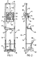
- FIG. 1 they show a cutting apparatus having two disc blades 2 mounted on a carriage 4.
- the blades 2 are angled towards each other such that their cutting edges 5 are proximate.
- the blades 2 are mounted on two first axles 6, supported by two radial arms 8. Also on the first axles 6 are first pulley wheels 10. Two second axles 12, supported by two mounting plates 14, have two second pulley wheels 16 co-linear with the first pulley wheels 10. Between the first and second pulley wheels 10,16 are first drive belts 17 (shown in dotted line).
- the second axles 12 extend into a transmission box 18 and have bevelled cog wheels 20 at their ends so that the second axles 12 rotate together.
- One second axle 12 also has a drive pulley wheel 22 which is co-linear with the drive wheel of an electric motor 24. Between the latter wheels is a second drive belt 26.
- the electric motor 24 drives the drive pulley wheel 22, hence both second axles 12 (via the transmission box 18), both first axles 6 and thus the blades 2. Whilst not shown in Fig. 3 for clarity, Figs. 1 and 2 show blade guards 28 and first drive pulley guards 30 to provide protection against these parts during use.
- the carriage 4 is mounted on an elongate support frame 32 having two parallel guides 34, top and bottom cross-members 36, and carriage support cross members 38.
- the carriage cross members 38 track the guides 34 using guide wheels 39, and the upper carriage cross member 38 is connected, e.g. by a wire rope 40 entrained around frame pulleys 41, to a winding mechanism 42.
- the construction and operation of the winding mechanism 42 corresponds to that as described on pages 5 onwards of GB 2 202 788 A. Rotation of the handle 44 causes winding of the reel 46 around which the wire rope 40 is entrained, causing the carriage 4 to move longitudinally along the guides 34.
- the support frame 32 includes spacer bars 48 to ensure correct distancing of the frame 32 from the surface 50 to be cut.
- the frame 32 has wheels 52 to assist transport of the frame 32 for relocation, and a piston and cylinder arrangement 58 which can rotate a foot bar 60, which bar 60 is rotatable about the axis of the wheels 52 to secure the frame 32 in position for use.
- Fig. 4 shows diagrammatically the operation of engagement of the blades 2 into a surface 50. Whilst angled blades 2 (that is, blades directed to be at an angle to the surface) could be driven into the surface directly, or possible with ease when the cutting apparatus is freely held or supported, it is preferred for the operation of the blades 2 on the carriage 4 and frame 32 in this embodiment for the blades 2 to be driven into the surface 50 vertically.
- the arms 8 supporting the blades 2 are rotatable about the second axles 12 using bushes (not shown) on the axles 12.
- the arms 8 are also attached to cutting handles 62 via three-point linkages 64. One end of the cutting handles 62 is attached to the mounting plates 14, whilst the other end extends outwardly from the carriage 4. Movement of the handles 62 rotates the arms 8 and hence blades 2.
- the two handles 62 may be linked or separate.
- the frame 32 is located against a desired surface 50.
- the spacer bars 48 provide correct distancing of the frame 32 from the wall 50.
- a handle 66 of the piston and cylinder arrangement 58 extends the piston downwardly to secure the foot bar 60 against a bottom surface (e.g. floor) and secure the frame 32.
- the top cross member 36 abuts an upper surface (e.g. ceiling), or spacers can be put therebetween to confirm such engagement.
- the motor 24 is started to rotate the blades 2, and the blades 2 are introduced into the surface 50 by moving the cutting handles 62 to a transverse position (Fig. 4).
- the blades 2 create a V-cut, but with the bulk of material 68 (that not directly cut by the blades 2) still held to the surface by a neck 70.
- the carriage 4 is progressed along the surface 50 by guidance within the frame 32 to create the required V-cut. Water is directed via nozzles 72 at the cutting to reduce the heat of the blades 2, and to dampen and reduce dust created by the cutting. Once finished, the blades 2 are withdrawn from the surface 50 by moving the cutting handles 62 upwardly.
- the remaining material 68 is very simply and easily removed by breaking the neck 70, possibly with just a screwdriver.
- This material 68 being the bulk of material removed for the track created, is thus removed still in solid form, rather than having been chipped or chiselled away (with attendant debris and mess).
- the present invention creates little mess and debris, especially scattered debris, requiring time and effort to clear away.
Landscapes
- Engineering & Computer Science (AREA)
- Mechanical Engineering (AREA)
- Mining & Mineral Resources (AREA)
- Processing Of Stones Or Stones Resemblance Materials (AREA)
- Knives (AREA)
Claims (14)
- Dispositif de coupe apte à faire des découpes en forme de V dans la surface d'un mur ou du sol (50), de manière à former une rainure apte à accueillir des fils ou des tuyaux, le dispositif comprenant deux lames de disque entraínées (2) montées sur un moyen de chariot (4) qui lui permet de se déplacer le long ou en travers de la surface (50), dans lequel les lames (2) sont inclinées l'une vers l'autre de telle sorte que les bords coupants (2) des lames soient proches, et dans lequel le moyen de chariot (4) comprend deux bras (8) et un support de connexion, chaque bras (8) supportant un essieu (6) sur lequel une lame (2) est montée.
- Dispositif de coupe suivant la revendication 1, caractérisé en ce que l'espace entre les bords coupants (5) des lames (2) est apte à laisser un 'col' (70) de matière encore attaché à la surface (50) après le passage du dispositif de coupe.
- Dispositif de coupe suivant la revendication 1 ou la revendication 2, caractérisé en ce qu'un ou plusieurs courants ou jets de liquide sont dirigés aux ou à proximité des bords coupants (5) des lames (2) durant l'utilisation.
- Dispositif de coupe suivant la revendication 1, 2 ou 3, caractérisé en ce que chaque bras (8) est mobile entre une position de départ désengagée avant la coupe et une position de coupe engagée.
- Dispositif de coupe suivant la revendication 4, caractérisé en ce que les bras (8) sont mobiles par une rotation autour d'axes pivotants entre le support de connexion et les bras (8) afin de déplacer les lames (2) entre une position de départ à l'écart de la surface (50) et une position engagée à l'intérieur de la surface (50).
- Dispositif de coupe suivant l'une quelconque des revendications précédentes, caractérisé en ce que les lames (2) sont actionnées par une source de courant centrale (24) à l'aide d'un moyen de transmission réparti vers les lames (2).
- Dispositif de coupe suivant la revendication 6, caractérisé en ce que le moyen de transmission comprend un ou plusieurs engrenage(s) conique(s) (20).
- Dispositif de coupe suivant la revendication 6 ou 7, caractérisé en ce que le moyen de transmission comprend au moins une poulie de commande pour chaque lame (2).
- Dispositif de coupe suivant la revendication 8, caractérisé en ce que la tension dans la ou dans chaque poulie est réglable.
- Dispositif de coupe suivant l'une quelconque des revendications précédentes, caractérisé en ce que l'angle entre les lames (2) est réglable.
- Dispositif de coupe suivant l'une quelconque des revendications précédentes, caractérisé en ce que l'angle entre les lames (2) est égal à ou est proche de 60°.
- Dispositif de coupe suivant l'une quelconque des revendications précédentes, caractérisé en ce que le dispositif de coupe est attaché à ou comprend un support.
- Dispositif de coupe suivant la revendication 12, caractérisé en ce que le support est un cadre allongé (32) comportant deux guides parallèles (34) permettant de faire glisser le moyen de chariot (4) le long de la surface (50).
- Dispositif de coupe suivant la revendication 13, caractérisé en ce que le cadre allongé (32) comprend un ensemble équipé de roues (52, 58, 60) monté à une extrémité du cadre (32), l'ensemble étant adapté de manière à entrer en contact avec la surface et à aider à fixer le cadre contre la surface (50).
Applications Claiming Priority (2)
| Application Number | Priority Date | Filing Date | Title |
|---|---|---|---|
| GBGB9624326.6A GB9624326D0 (en) | 1996-11-22 | 1996-11-22 | Cutting apparatus |
| GB9624326 | 1996-11-22 |
Publications (3)
| Publication Number | Publication Date |
|---|---|
| EP0849059A2 EP0849059A2 (fr) | 1998-06-24 |
| EP0849059A3 EP0849059A3 (fr) | 1998-10-14 |
| EP0849059B1 true EP0849059B1 (fr) | 2004-06-09 |
Family
ID=10803337
Family Applications (1)
| Application Number | Title | Priority Date | Filing Date |
|---|---|---|---|
| EP19970309392 Expired - Lifetime EP0849059B1 (fr) | 1996-11-22 | 1997-11-21 | Dispositif de coupe à deux lames pour couper des rainures sous forme de V |
Country Status (3)
| Country | Link |
|---|---|
| EP (1) | EP0849059B1 (fr) |
| DE (1) | DE69729428D1 (fr) |
| GB (1) | GB9624326D0 (fr) |
Families Citing this family (6)
| Publication number | Priority date | Publication date | Assignee | Title |
|---|---|---|---|---|
| CN103706879B (zh) * | 2013-12-22 | 2016-04-13 | 吕宗树 | 建筑砌块的灰口槽的加工方法 |
| CN106948582B (zh) * | 2017-05-18 | 2023-12-05 | 赵佳丽 | 一种开槽机 |
| CN107253292A (zh) * | 2017-07-26 | 2017-10-17 | 高豹 | 一种v型切槽机 |
| CN109332902B (zh) * | 2018-10-31 | 2020-01-21 | 华中科技大学 | 一种混凝土路面激光切割辅助装置 |
| CN110303606B (zh) * | 2019-06-26 | 2020-08-07 | 中国地质大学(武汉) | 一种便携式原岩结构面表面形貌加工装置及其操作方法 |
| CN111941551B (zh) * | 2020-08-14 | 2021-05-07 | 杭州杭子木业有限公司 | 一种实木颗粒板材自动化精确切割加工机械 |
Family Cites Families (6)
| Publication number | Priority date | Publication date | Assignee | Title |
|---|---|---|---|---|
| FR1429447A (fr) * | 1965-01-11 | 1966-02-25 | Procédé de découpage d'onglets pour formation de cadres et machine pour sa mise en oeuvre | |
| US4208934A (en) * | 1979-03-20 | 1980-06-24 | Wall Leslie W | Miter saw machine |
| US4372174A (en) * | 1981-05-04 | 1983-02-08 | Petro-Canada Exploration Inc. | Method and apparatus for sampling a core of tar sand |
| DE3533757A1 (de) * | 1985-09-21 | 1987-04-02 | Klaus Mueller | Zwilling - gehrungsschneider |
| GB8706139D0 (en) * | 1987-03-16 | 1987-04-23 | Brown R | Cutting apparatus |
| DE9410988U1 (de) * | 1994-07-08 | 1994-09-15 | Weber Maschinentechnik GmbH, 57334 Bad Laasphe | Wasserberieselung für Fugenschneider |
-
1996
- 1996-11-22 GB GBGB9624326.6A patent/GB9624326D0/en active Pending
-
1997
- 1997-11-21 DE DE69729428T patent/DE69729428D1/de not_active Expired - Lifetime
- 1997-11-21 EP EP19970309392 patent/EP0849059B1/fr not_active Expired - Lifetime
Also Published As
| Publication number | Publication date |
|---|---|
| EP0849059A2 (fr) | 1998-06-24 |
| GB9624326D0 (en) | 1997-01-08 |
| EP0849059A3 (fr) | 1998-10-14 |
| DE69729428D1 (de) | 2004-07-15 |
Similar Documents
| Publication | Publication Date | Title |
|---|---|---|
| US6536422B1 (en) | Saw for cutting green concrete | |
| US4193636A (en) | Asphalt paving planer with conveyor forwardly of cutting drum | |
| US4880491A (en) | Guided roofing materials removal apparatus | |
| US4232719A (en) | Brush harvester | |
| US5098165A (en) | Guided roofing materials removal apparatus | |
| CA2654189A1 (fr) | Appareil de decoupe hydraulique de dalles, monte sur un vehicule | |
| US5078119A (en) | Chain saw cutting assembly | |
| EP0849059B1 (fr) | Dispositif de coupe à deux lames pour couper des rainures sous forme de V | |
| GB2315796A (en) | Reversable plate compactor having directional control | |
| US4986252A (en) | Chain saw cutting assembly | |
| US6390086B1 (en) | Mobile concrete saw | |
| AU549577B2 (en) | Portable power saw mill | |
| CN113047144A (zh) | 一种用于水泥混凝土铺面板的全厚式整体快速切割装备 | |
| US2569682A (en) | Means for cutting pavement and other like surfaces | |
| EP0686466B1 (fr) | Machine de découpage à plusieurs lames de coupe pour couper des blocs de granit ou similaires et installation | |
| IE87362B1 (en) | A cutting device | |
| GB2202788A (en) | Apparatus for cutting channels in walls | |
| US8967729B1 (en) | Trip hazard removal system and method | |
| CN222499925U (zh) | 一种高速公路养护用钢筋头清除装置 | |
| CN220565021U (zh) | 一种切槽设备 | |
| JPH0527760B2 (fr) | ||
| JP2000043027A (ja) | 水平溝形成用切断機および水平溝形成方法 | |
| US20240239016A1 (en) | Sawcut machine for sidewalks | |
| US20240227241A9 (en) | Concrete saw with cutting enclosure and dust collection system | |
| CN211518053U (zh) | 一种用于石材切割机的除尘装置 |
Legal Events
| Date | Code | Title | Description |
|---|---|---|---|
| PUAI | Public reference made under article 153(3) epc to a published international application that has entered the european phase |
Free format text: ORIGINAL CODE: 0009012 |
|
| AK | Designated contracting states |
Kind code of ref document: A2 Designated state(s): DE DK FR GB IE SE |
|
| AX | Request for extension of the european patent |
Free format text: AL;LT;LV;MK;RO;SI |
|
| PUAL | Search report despatched |
Free format text: ORIGINAL CODE: 0009013 |
|
| AK | Designated contracting states |
Kind code of ref document: A3 Designated state(s): AT BE CH DE DK ES FI FR GB GR IE IT LI LU MC NL PT SE |
|
| AX | Request for extension of the european patent |
Free format text: AL;LT;LV;MK;RO;SI |
|
| 17P | Request for examination filed |
Effective date: 19990413 |
|
| AKX | Designation fees paid |
Free format text: DE DK FR GB IE SE |
|
| 17Q | First examination report despatched |
Effective date: 20020226 |
|
| GRAH | Despatch of communication of intention to grant a patent |
Free format text: ORIGINAL CODE: EPIDOS IGRA |
|
| GRAS | Grant fee paid |
Free format text: ORIGINAL CODE: EPIDOSNIGR3 |
|
| GRAA | (expected) grant |
Free format text: ORIGINAL CODE: 0009210 |
|
| AK | Designated contracting states |
Kind code of ref document: B1 Designated state(s): DE DK FR GB IE SE |
|
| PG25 | Lapsed in a contracting state [announced via postgrant information from national office to epo] |
Ref country code: FR Free format text: LAPSE BECAUSE OF FAILURE TO SUBMIT A TRANSLATION OF THE DESCRIPTION OR TO PAY THE FEE WITHIN THE PRESCRIBED TIME-LIMIT Effective date: 20040609 |
|
| REG | Reference to a national code |
Ref country code: GB Ref legal event code: FG4D |
|
| REF | Corresponds to: |
Ref document number: 69729428 Country of ref document: DE Date of ref document: 20040715 Kind code of ref document: P |
|
| REG | Reference to a national code |
Ref country code: IE Ref legal event code: FG4D |
|
| PG25 | Lapsed in a contracting state [announced via postgrant information from national office to epo] |
Ref country code: SE Free format text: LAPSE BECAUSE OF FAILURE TO SUBMIT A TRANSLATION OF THE DESCRIPTION OR TO PAY THE FEE WITHIN THE PRESCRIBED TIME-LIMIT Effective date: 20040909 Ref country code: DK Free format text: LAPSE BECAUSE OF FAILURE TO SUBMIT A TRANSLATION OF THE DESCRIPTION OR TO PAY THE FEE WITHIN THE PRESCRIBED TIME-LIMIT Effective date: 20040909 |
|
| PG25 | Lapsed in a contracting state [announced via postgrant information from national office to epo] |
Ref country code: DE Free format text: LAPSE BECAUSE OF FAILURE TO SUBMIT A TRANSLATION OF THE DESCRIPTION OR TO PAY THE FEE WITHIN THE PRESCRIBED TIME-LIMIT Effective date: 20040910 |
|
| REG | Reference to a national code |
Ref country code: GB Ref legal event code: 732E |
|
| RAP2 | Party data changed (patent owner data changed or rights of a patent transferred) |
Owner name: BROWN, ROBERT |
|
| RIN2 | Information on inventor provided after grant (corrected) |
Inventor name: BROWN, ROBERT Inventor name: SPEEDIE, ANDREW |
|
| PLBE | No opposition filed within time limit |
Free format text: ORIGINAL CODE: 0009261 |
|
| STAA | Information on the status of an ep patent application or granted ep patent |
Free format text: STATUS: NO OPPOSITION FILED WITHIN TIME LIMIT |
|
| 26N | No opposition filed |
Effective date: 20050310 |
|
| EN | Fr: translation not filed | ||
| PGFP | Annual fee paid to national office [announced via postgrant information from national office to epo] |
Ref country code: IE Payment date: 20060117 Year of fee payment: 9 |
|
| PG25 | Lapsed in a contracting state [announced via postgrant information from national office to epo] |
Ref country code: IE Free format text: LAPSE BECAUSE OF NON-PAYMENT OF DUE FEES Effective date: 20061121 |
|
| GBPC | Gb: european patent ceased through non-payment of renewal fee |
Effective date: 20061121 |
|
| REG | Reference to a national code |
Ref country code: IE Ref legal event code: MM4A |
|
| PG25 | Lapsed in a contracting state [announced via postgrant information from national office to epo] |
Ref country code: GB Free format text: LAPSE BECAUSE OF NON-PAYMENT OF DUE FEES Effective date: 20061121 |
|
| PGFP | Annual fee paid to national office [announced via postgrant information from national office to epo] |
Ref country code: GB Payment date: 20060117 Year of fee payment: 9 |