EP0849078A1 - Dispositif pour éviter le jeu entre les dents d'une première et d'une deuxième roue dentée dans une unité d'impression d'une rotative offset - Google Patents
Dispositif pour éviter le jeu entre les dents d'une première et d'une deuxième roue dentée dans une unité d'impression d'une rotative offset Download PDFInfo
- Publication number
- EP0849078A1 EP0849078A1 EP97120239A EP97120239A EP0849078A1 EP 0849078 A1 EP0849078 A1 EP 0849078A1 EP 97120239 A EP97120239 A EP 97120239A EP 97120239 A EP97120239 A EP 97120239A EP 0849078 A1 EP0849078 A1 EP 0849078A1
- Authority
- EP
- European Patent Office
- Prior art keywords
- gear
- leaf spring
- recess
- teeth
- spring arrangement
- Prior art date
- Legal status (The legal status is an assumption and is not a legal conclusion. Google has not performed a legal analysis and makes no representation as to the accuracy of the status listed.)
- Withdrawn
Links
- 238000007639 printing Methods 0.000 title claims description 19
- 238000007645 offset printing Methods 0.000 title 1
- 230000000712 assembly Effects 0.000 claims description 6
- 238000000429 assembly Methods 0.000 claims description 6
- 230000002093 peripheral effect Effects 0.000 claims description 2
- 230000007935 neutral effect Effects 0.000 abstract 1
- 230000006835 compression Effects 0.000 description 2
- 238000007906 compression Methods 0.000 description 2
- 230000036316 preload Effects 0.000 description 2
- 238000000926 separation method Methods 0.000 description 2
- 150000001875 compounds Chemical class 0.000 description 1
- 230000003247 decreasing effect Effects 0.000 description 1
- 230000003292 diminished effect Effects 0.000 description 1
- 230000007257 malfunction Effects 0.000 description 1
- 238000004519 manufacturing process Methods 0.000 description 1
- 230000003068 static effect Effects 0.000 description 1
- 238000004804 winding Methods 0.000 description 1
Images


Classifications
-
- F—MECHANICAL ENGINEERING; LIGHTING; HEATING; WEAPONS; BLASTING
- F16—ENGINEERING ELEMENTS AND UNITS; GENERAL MEASURES FOR PRODUCING AND MAINTAINING EFFECTIVE FUNCTIONING OF MACHINES OR INSTALLATIONS; THERMAL INSULATION IN GENERAL
- F16H—GEARING
- F16H55/00—Elements with teeth or friction surfaces for conveying motion; Worms, pulleys or sheaves for gearing mechanisms
- F16H55/02—Toothed members; Worms
- F16H55/17—Toothed wheels
- F16H55/18—Special devices for taking up backlash
-
- B—PERFORMING OPERATIONS; TRANSPORTING
- B41—PRINTING; LINING MACHINES; TYPEWRITERS; STAMPS
- B41F—PRINTING MACHINES OR PRESSES
- B41F13/00—Common details of rotary presses or machines
- B41F13/008—Mechanical features of drives, e.g. gears, clutches
- B41F13/012—Taking-up backlash
-
- B—PERFORMING OPERATIONS; TRANSPORTING
- B41—PRINTING; LINING MACHINES; TYPEWRITERS; STAMPS
- B41P—INDEXING SCHEME RELATING TO PRINTING, LINING MACHINES, TYPEWRITERS, AND TO STAMPS
- B41P2213/00—Arrangements for actuating or driving printing presses; Auxiliary devices or processes
- B41P2213/10—Constitutive elements of driving devices
- B41P2213/20—Gearings
-
- Y—GENERAL TAGGING OF NEW TECHNOLOGICAL DEVELOPMENTS; GENERAL TAGGING OF CROSS-SECTIONAL TECHNOLOGIES SPANNING OVER SEVERAL SECTIONS OF THE IPC; TECHNICAL SUBJECTS COVERED BY FORMER USPC CROSS-REFERENCE ART COLLECTIONS [XRACs] AND DIGESTS
- Y10—TECHNICAL SUBJECTS COVERED BY FORMER USPC
- Y10T—TECHNICAL SUBJECTS COVERED BY FORMER US CLASSIFICATION
- Y10T74/00—Machine element or mechanism
- Y10T74/19—Gearing
- Y10T74/19623—Backlash take-up
-
- Y—GENERAL TAGGING OF NEW TECHNOLOGICAL DEVELOPMENTS; GENERAL TAGGING OF CROSS-SECTIONAL TECHNOLOGIES SPANNING OVER SEVERAL SECTIONS OF THE IPC; TECHNICAL SUBJECTS COVERED BY FORMER USPC CROSS-REFERENCE ART COLLECTIONS [XRACs] AND DIGESTS
- Y10—TECHNICAL SUBJECTS COVERED BY FORMER USPC
- Y10T—TECHNICAL SUBJECTS COVERED BY FORMER US CLASSIFICATION
- Y10T74/00—Machine element or mechanism
- Y10T74/19—Gearing
- Y10T74/1987—Rotary bodies
- Y10T74/19893—Sectional
- Y10T74/19898—Backlash take-up
Definitions
- the present invention relates to a device for avoiding play between the meshing teeth of a first and a second gear, e.g. B. between the interlocking teeth of a plate cylinder gear and a corresponding one Blanket cylinder gear in a printing unit of an offset rotary printing machine according to the preamble of claim 1.
- the teeth of a first gear meshing with the teeth of a corresponding second gear, e.g. B. the teeth of a driving gear meshing with the teeth of a driven gear of a gear train usually tend to separate circumferentially from each other when the gears rotate at very high speeds.
- the teeth of a driving gear fixed to a blanket cylinder in a printing unit of a rotary printing press have a tendency to separate circumferentially from the teeth of a gear fixed to an adjacent plate cylinder of the printing unit when the cylinders rotate at very high speeds.
- This extensive separation of the teeth from each other is often the cause of register errors, which is then a so-called Duplicate "the halftone dots, which significantly affects the quality of the printed product, especially in an offset rotary printing press.
- US 5,357,858 discloses a device for avoiding peripheral separation of the meshing teeth of a blanket cylinder gear and a platter cylinder gear from each other.
- the first gear moves around an axis, and a coaxial to first gear arranged second gear moves relative to the same axis to the first gear.
- the teeth of a third gear mesh with the teeth of the second gear.
- a fourth gear arranged coaxially with the plate cylinder gear is moving with this, and the teeth of the fourth gear mesh with the teeth of the third gear.
- the device further comprises an elastic, prestressed Torsion spring with a conventional winding that the first and the second gear drives connected, namely via a fixedly connected to the first gear Shaft passing through an opening in the center of the second gear along the Axis of rotation of the first and second gear extends.
- the first and the second gear around its common axis of rotation in opposite directions biased. Because that exerted on the shaft by the prestressed torsion spring Torque generates a radial force on the shaft at the point where the end the torsion spring connected to the shaft, the support bearings of the shaft are high Dimensions claimed, which leads to increased wear of the bearings and other components Consequence. With such a configuration, bearing breaks can occur. It is also Device relatively large and includes a large number of items, which the Manufacturing costs of the device and also the risk of malfunction increased.
- US 3,407,727 discloses a device for avoiding play between the intermeshing teeth of a first gear fixed to a plate cylinder and one a rubber blanket cylinder fixed second gear in a rotary printing press, which is an additional or additional gear mounted coaxially to the first gear comprises, wherein the teeth of the idler gear and the first gear with the Comb teeth of the second gear.
- the attached gear and the first gear are formed by a spiral spring, which is formed in an enclosed gear Recess is arranged and with its first end on the adjacent gear and with its second end on one on the adjacent outer surface of the first gear fixed screw mechanism attached, preloaded so that the gears rotate in opposite directions.
- the spring force of the Spiral compression spring can be changed via the screw mechanism. Because of the big Recess in the sprocket that is required to insert a coil spring to accommodate with a sufficiently high preload, the attached gear is in the part where the recess is located, of reduced stability. Besides, that is maximum force generated by the spiral compression spring is too low, d. H. she is not enough to play between the interacting plate cylinder and Blanket cylinder gears in conventional printing presses, the z. B. with Speeds of 100,000 revolutions per hour are operated, too avoid.
- the device according to the invention has the advantage that even with changing Distances between the centers of the gears (e.g. between the centers of the Plate cylinder gear and the blanket cylinder gear) forces are generated which cause the gears (e.g. an idler gear and a Plate cylinder gear) in opposite directions and thereby any Prevent play or even a gap between the gears, which in conventional Rotary printing machines, in which the static anti-play gears on only one fixed clearance between the centers of the meshing gears and not on Changes in the distances between the gear centers work, not the case.
- a device for avoidance comprises of play between the meshing teeth of a first and a second gear, e.g. B. a plate cylinder gear and a corresponding blanket cylinder gear in a printing unit of an offset rotary printing press, an additional or Adjacent gear that rotates next to the first gear and on its axis of rotation is mounted, the teeth of the adjacent gear with the teeth of the second Comb gear.
- a support element is at least one of the first and attached gear fixed.
- a leaf spring arrangement has a first End part on, which is substantially radial with respect to the axis of rotation of the first gear extends, with a second end portion of the leaf spring assembly moving from the zero position and brought into contact with the support member to force the support member to act, which biases the adjacent and the first gear, so that this in turn in opposite directions.
- the support element is by a pin or Bolt formed from the first gear or from the accompanying gear on the side protrudes.
- the leaf spring arrangement is e.g. B. outside the adjacent gear arranged. According to a further embodiment of the invention, this extends second end of the leaf spring assembly in a recess in the first gear or accompanying gear can be shaped, the support member on the side wall of the Recess is formed.
- the first gear includes z. B. a sleeve-shaped coaxial projection that extends through a central recess formed in the adjacent gear extends, the Inner diameter of this central recess and the outer diameter of the sleeve-shaped coaxial projection are designed such that the accompanying gear rotatably supported on the sleeve-shaped coaxial projection and with respect to the Axis of rotation of the first gear is radially immovable.
- the leaf spring arrangement can be arranged in the radially extending recess a pin or bolt extending radially through respective openings will.
- the openings in the sleeve-shaped coaxial Projection and be formed in the first end portion of the leaf spring assembly.
- the leaf spring arrangement in the radially extending recess axially secured by a bracket is secured by a bracket.
- the sleeve-shaped projection is by means of Bolt attached to the first gear.
- Another embodiment provides another pin on the first gear, the from the side wall of the first gear to one in the adjacent gear Shaped further recess extends to a freewheel of the accompanying gear prevent when the idler gear and the second gear come out of engagement.
- the further recess of the adjacent gear can have an elliptical shape, and the leaf spring arrangement can be two or more individual Include leaf springs that are attached together to the first end portion.
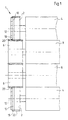
- Fig. 1 shows a device 1 to avoid play between the meshing Teeth of a first and a second gear, e.g. B. the driving gear 2 one Plate cylinder 4 and the driving gear 6 of an associated, adjacent Blanket cylinder 8 of a printing unit. 1 comprises a device additional or incidental gear 10, which is mounted next to the first gear 2.
- the idler gear 10 is around same axis of rotation 12 as the first gear 2 rotatable.
- the additional gear 10 is mounted on a sleeve-shaped coaxial projection 14, which is formed, for example, as an integral part of the body of the first gear 2 or on the body of the first gear 2 z. B. by means of bolts or screws 16 can be attached.
- the accompanying gear 10 is preferably ring-shaped, with the inside shaped central recess has an inner diameter that is slightly larger than the outer diameter of the sleeve-shaped projection 14. So that's additional Gear 10 on the one hand rotatably supported on the sleeve-shaped projection 14, on the other hand however, radially immovable with respect to the axis of rotation 12 of the first gear 2.
- the idler gear 10 can be used instead of the above described way also on roles (z. B. three or more roles), pens or protruding parts, which instead of the sleeve-shaped projection 14 on the body of the first gear 2 are attached, rotatably mounted so that it is not radial is movable, but is mounted coaxially rotatable with respect to the first gear 2.
- the spur gear has 10 teeth 18, which mesh with the teeth 20 of the second gear 6.
- the attached gear 10 and the first gear 2 are therefore mounted parallel to one another in such a way that both the teeth 18 of the accompanying gear 10 and the teeth 22 of the first gear 2 with the Comb teeth 20 of second gear 6.
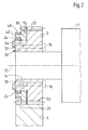
- a leaf spring arrangement 24 is driven with a first end portion 26 sleeve-shaped projection 14 connected. As shown in Figs. 2, 3A and 4, this is first end part 26 in a substantially radially extending recess 28 in the Body of the sleeve-shaped projection 14 is added.
- the sleeve-shaped projection 14 axially next to the accompanying gear 10th be arranged, d. H. that the position where the recess 28 in the sleeve-shaped Projection 14 is formed, may lie in a part of this projection 14, which is axially is located next to the part on which the enclosed gear 10 is rotatably mounted is.
- the recess 28 in the sleeve-shaped projection 14 in the direction of the end surface 30 of the sleeve-shaped projection 14 be open, the leaf spring assembly 24 z. B. by means of a bracket 32 which with respective screws or bolts 34 over the Recess 28 is secured, axially secured as shown in FIGS. 2-4 is shown.
- the leaf spring arrangement 24 in the radial recess 28 z. B. by means of a through a respective opening in the first end part 26 of the Leaf spring assembly 24 extending pin or bolt 36 are fixed radially.
- the pin or bolt 36 can also in one Recess 38 may be included, which z. B.
- the leaf spring assembly 24 can be together with the pin or bolt 36 by attaching or removing the bracket 32 by means of the Bolt 34 can be easily attached and released. Accordingly, the Leaf spring assembly 24 can be easily replaced with one that has other features, e.g. B. a leaf spring with a different stiffness or spring characteristic. Thus, the Device easily adapted to different machine types or working conditions will.
- a second end part 40 makes contact the leaf spring arrangement 24 a formed on the accompanying gear 10 Support element 42.
- the support element 42 can e.g. B. a from the accompanying gear 10 laterally protruding pin or bolt.
- the support member 42 has a length that is approximately the depth of the leaf spring assembly 24 (see Fig. 2) corresponds.
- the leaf spring arrangement 24 for driving connection than on the first gear 2 shown attached is not limited to such an embodiment.
- the first end part 26 of the leaf spring arrangement can be attached to the adjacent one Gear 10 may be attached (e.g., fixed) in a manner similar to that previously described with reference to FIG the attachment of the first end part (26) to the sleeve-shaped projection (14) is.
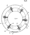
- a mounting example is shown in FIG. 3B, in which elements similar to those of FIG 3A are shown. 3B, the support element 42 is on the sleeve-shaped projection 14 attached.
- the relative widths of the incoming Gear 10 and the sleeve-shaped projection 14 modified.
- the width of the accompanying gear 10 viewed in the axial direction over the sleeve-shaped Projection 14 extends so that the second end portion 40 of the leaf spring assembly outside the outer surface of the sleeve-shaped projection 14 or in a recess is positioned.
- the second end part 40 of the leaf spring arrangement 24 can be made of its radial zero position (i.e. from a vertical position shown in FIG. 4) a distance of about 0.1 to 2.5 mm, for example, when the Device is assembled, wherein a force is exerted on the support element 42, which gives the adjacent gear 10 and the first gear 2 a bias, so that they rotate in opposite directions to each other.
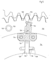
- FIG. 5 there is a second one End portion 140 of a leaf spring assembly 124 in a direct in an accompanying Gear 110 shaped recess 144 positioned so that it is in contact with a support element 142 formed in the accompanying gear 110.
- a first end portion 126 of the leaf spring assembly 124 also in a recess 128 positioned in the body one attached to the first gear 2 sleeve-shaped projection 114 is formed.
- the recess 128 is not axially adjacent to the one that runs along Gear 110, but immediately below the body of the accompanying gear 110 arranged.
- the leaf spring assembly 124 can this version z. B. by a bolt or pin 136 extending through the first End portion 126 of the leaf spring assembly 124 extends and in a recess 138 in the Body of the sleeve-shaped projection 114 is arranged to be secured radially.
- the Recess 138 for receiving the bolt 136 and the recess 128 for receiving of the first end portion 126 of the leaf spring assembly 124 are also preferably in Direction of the end surface of the sleeve-shaped projection 114 open.
- Leaf spring arrangement 124 by means of a bracket 132 and respective bolts or Screws 134 are axially secured in the recess 128, as in 1-4 is described, so that the leaf spring assembly 124th together with the bolt 136 for the radial securing of the leaf spring arrangement 124 can be easily attached and removed.
- a further pin 50 according to the 3A and 4 or a pin 150 according to FIG. 5 can be provided on the first gear 2, which extends from the side wall of the first gear 2 into a respective further one in the respective recessed gear 10, 110 shaped recess 52, 152 extends.
- the Recess 52, 152 can e.g. B. of circular or elliptical shape.
- any number of leaf spring assemblies can be used.
- any number of leaf spring assemblies can be used.
- the leaf spring assemblies around the center of the sleeve-shaped projection 14th i.e. a center corresponding to the axis of rotation 12 of the first gear 2 in radially opposite pairs can be arranged.
- Such an arrangement reduces or prevents wear-promoting compound torques that arise because each of the leaf spring assemblies alone tends to run alongside Gear 10, 110 to rotate axes perpendicular to the axis of rotation of the first gear run. This means that when the leaf spring assemblies are placed in radial relation to one another opposite pairs all with respect to one perpendicular to the axis of rotation of the first Gear 2 extending axis acting torques can be compensated.
- FIG. 3A In the embodiment of FIG. 3A, six leaf spring arrangements are shown, which around the sleeve-shaped projection 14, 114 with uniform circumferential spacing are placed from each other.
- the biasing forces for turning the accompanying gear 10, 110 with respect to the first gear 2 or slightly reduced can be multiplied, and the magnitude of the preload can easily be different Machine types and / or working conditions can be adapted.
- the Adjustment of the pretensioning forces can be achieved simply by one, two or several leaf spring assemblies 24, 124 is dispensed with.
- the biasing forces by varying (i.e. increasing or decreasing) the number of leaf springs in each Leaf spring assembly (e.g., four leaf springs for each of the six shown in Figure 3A Arrangements on six, seven or any number of leaf springs) can be changed.
Landscapes
- Engineering & Computer Science (AREA)
- General Engineering & Computer Science (AREA)
- Mechanical Engineering (AREA)
- Gears, Cams (AREA)
- Rotary Presses (AREA)
Applications Claiming Priority (2)
| Application Number | Priority Date | Filing Date | Title |
|---|---|---|---|
| US769055 | 1991-10-04 | ||
| US08/769,055 US5813335A (en) | 1996-12-18 | 1996-12-18 | Apparatus for preventing backlash between the meshing teeth of a first and a second gear in a printing unit of a lithographic rotary printing press |
Publications (1)
| Publication Number | Publication Date |
|---|---|
| EP0849078A1 true EP0849078A1 (fr) | 1998-06-24 |
Family
ID=25084305
Family Applications (1)
| Application Number | Title | Priority Date | Filing Date |
|---|---|---|---|
| EP97120239A Withdrawn EP0849078A1 (fr) | 1996-12-18 | 1997-11-19 | Dispositif pour éviter le jeu entre les dents d'une première et d'une deuxième roue dentée dans une unité d'impression d'une rotative offset |
Country Status (3)
| Country | Link |
|---|---|
| US (1) | US5813335A (fr) |
| EP (1) | EP0849078A1 (fr) |
| DE (1) | DE19751117A1 (fr) |
Cited By (5)
| Publication number | Priority date | Publication date | Assignee | Title |
|---|---|---|---|---|
| FR2803794A1 (fr) * | 2000-01-15 | 2001-07-20 | Roland Man Druckmasch | Dispositif de suppression du jeu dans des trains de roues dentees de machines a imprimer |
| DE102007020225A1 (de) | 2007-04-28 | 2008-10-30 | Koenig & Bauer Aktiengesellschaft | Vorrichtung zur Synchronisierung der Drehbewegung von einzeln angetriebenen Rotationskörpern |
| DE202010016197U1 (de) | 2010-12-06 | 2011-02-17 | Wmh Herion Antriebstechnik Gmbh | Spielfrei laufendes Zahnrad |
| EP3441224A1 (fr) * | 2017-08-11 | 2019-02-13 | Valeo Schalter und Sensoren GmbH | Système de roue dentée et dispositif capteur |
| CN109562616A (zh) * | 2016-07-04 | 2019-04-02 | 艾美企画股份有限公司 | 具有印版滚筒驱动装置的印刷机 |
Families Citing this family (15)
| Publication number | Priority date | Publication date | Assignee | Title |
|---|---|---|---|---|
| JP3562948B2 (ja) | 1997-10-13 | 2004-09-08 | トヨタ自動車株式会社 | ハイポイドギヤ構造 |
| US6148684A (en) * | 1999-03-10 | 2000-11-21 | Heidelberger Druckmaschinen Aktiengesellschaft | Anti-backlash gear |
| FR2806690B1 (fr) * | 2000-03-24 | 2002-08-23 | Renault | Colonne de direction comportant un dispositif d'assistance |
| CA2440792A1 (fr) * | 2002-09-27 | 2004-03-27 | Mechworks Systems Inc. | Methode et systeme de controle en ligne de l'etat de machines rotatives multietagees |
| JP2007021858A (ja) * | 2005-07-15 | 2007-02-01 | Komori Corp | 移動型インキユニットを備えた印刷機 |
| JP2008073924A (ja) * | 2006-09-20 | 2008-04-03 | Duplo Seiko Corp | 孔版印刷装置 |
| DE102007025752A1 (de) * | 2007-06-01 | 2008-12-04 | Manroland Ag | Angetriebene Baugruppe einer Druckmaschine |
| US7752937B1 (en) * | 2009-12-21 | 2010-07-13 | Winzeler Gear, Inc | Anti-backlash gear |
| AT510283B1 (de) * | 2010-09-29 | 2012-03-15 | Miba Sinter Austria Gmbh | Zahnradanordnung |
| CN103619592B (zh) * | 2011-02-15 | 2015-11-25 | 艾美株式会社 | 印刷机的印版滚筒驱动装置 |
| EP2914877B1 (fr) * | 2012-10-31 | 2021-02-03 | Parker-Hannifin Corporation | Système de commande d'engrenage pour atténuer les vibrations |
| US9618108B2 (en) * | 2013-07-17 | 2017-04-11 | Achates Power, Inc. | Gear noise reduction in opposed-piston engines |
| AT517424B1 (de) * | 2015-06-25 | 2019-09-15 | Miba Sinter Austria Gmbh | Vorrichtung zur Spielfreistellung kämmender Verzahnungen eines Zahnradantriebs |
| AT517484B1 (de) * | 2015-10-06 | 2017-02-15 | Metaldyne Int Deutschland Gmbh | Zahnradanordnung |
| DE102017126205A1 (de) * | 2017-11-09 | 2019-05-09 | Man Truck & Bus Ag | Zahnrad, insbesondere Zwischenrad, für einen Rädertrieb |
Citations (6)
| Publication number | Priority date | Publication date | Assignee | Title |
|---|---|---|---|---|
| US1486423A (en) * | 1923-04-12 | 1924-03-11 | Anton F Ericson | Gearing |
| FR979448A (fr) * | 1942-04-17 | 1951-04-26 | Dispositif de rattrapage de jeu automatique pour pignons ou engrenages en général | |
| US2966806A (en) * | 1958-07-28 | 1961-01-03 | Alfred O Luning | Antibacklash gears |
| US3035454A (en) * | 1960-06-01 | 1962-05-22 | Alfred O Luning | Antibacklash gear |
| US3407727A (en) * | 1966-03-23 | 1968-10-29 | Maschf Augsburg Nuernberg Ag | Supplementary driving gear arrangement for multi-color sheet-fed rotary printing presses |
| US4781073A (en) * | 1987-06-24 | 1988-11-01 | The United States Of America As Represented By The Secretary Of The Army | Adjustable antibacklash gear system |
Family Cites Families (3)
| Publication number | Priority date | Publication date | Assignee | Title |
|---|---|---|---|---|
| US4602523A (en) * | 1983-09-27 | 1986-07-29 | Nissan Motor Company, Ltd. | Steering system equipped with anti-rotation mechanism |
| SE466669B (sv) * | 1988-04-26 | 1992-03-16 | Volvo Ab | Anordning foer att daempa mekaniskt slammer i en vaexellaada |
| US5357858A (en) * | 1993-03-04 | 1994-10-25 | Heidelberg Druckmaschinen Ag | Apparatus for preventing circumferential separation between a blanket cylinder gear and a plate cylinder gear |
-
1996
- 1996-12-18 US US08/769,055 patent/US5813335A/en not_active Expired - Fee Related
-
1997
- 1997-11-18 DE DE19751117A patent/DE19751117A1/de not_active Withdrawn
- 1997-11-19 EP EP97120239A patent/EP0849078A1/fr not_active Withdrawn
Patent Citations (6)
| Publication number | Priority date | Publication date | Assignee | Title |
|---|---|---|---|---|
| US1486423A (en) * | 1923-04-12 | 1924-03-11 | Anton F Ericson | Gearing |
| FR979448A (fr) * | 1942-04-17 | 1951-04-26 | Dispositif de rattrapage de jeu automatique pour pignons ou engrenages en général | |
| US2966806A (en) * | 1958-07-28 | 1961-01-03 | Alfred O Luning | Antibacklash gears |
| US3035454A (en) * | 1960-06-01 | 1962-05-22 | Alfred O Luning | Antibacklash gear |
| US3407727A (en) * | 1966-03-23 | 1968-10-29 | Maschf Augsburg Nuernberg Ag | Supplementary driving gear arrangement for multi-color sheet-fed rotary printing presses |
| US4781073A (en) * | 1987-06-24 | 1988-11-01 | The United States Of America As Represented By The Secretary Of The Army | Adjustable antibacklash gear system |
Cited By (8)
| Publication number | Priority date | Publication date | Assignee | Title |
|---|---|---|---|---|
| FR2803794A1 (fr) * | 2000-01-15 | 2001-07-20 | Roland Man Druckmasch | Dispositif de suppression du jeu dans des trains de roues dentees de machines a imprimer |
| DE10001569A1 (de) * | 2000-01-15 | 2001-08-02 | Roland Man Druckmasch | Vorrichtung zur Spielfreistellung an Zahnräderzügen von Druckmaschinen |
| US6487965B2 (en) | 2000-01-15 | 2002-12-03 | Man Roland Druckmaschinen Ag | Apparatus for eliminating backlash in gear trains of printing machines |
| DE102007020225A1 (de) | 2007-04-28 | 2008-10-30 | Koenig & Bauer Aktiengesellschaft | Vorrichtung zur Synchronisierung der Drehbewegung von einzeln angetriebenen Rotationskörpern |
| DE202010016197U1 (de) | 2010-12-06 | 2011-02-17 | Wmh Herion Antriebstechnik Gmbh | Spielfrei laufendes Zahnrad |
| CN109562616A (zh) * | 2016-07-04 | 2019-04-02 | 艾美企画股份有限公司 | 具有印版滚筒驱动装置的印刷机 |
| CN109562616B (zh) * | 2016-07-04 | 2020-06-23 | 艾美企画股份有限公司 | 具有印版滚筒驱动装置的印刷机 |
| EP3441224A1 (fr) * | 2017-08-11 | 2019-02-13 | Valeo Schalter und Sensoren GmbH | Système de roue dentée et dispositif capteur |
Also Published As
| Publication number | Publication date |
|---|---|
| DE19751117A1 (de) | 1998-06-25 |
| US5813335A (en) | 1998-09-29 |
Similar Documents
| Publication | Publication Date | Title |
|---|---|---|
| EP0849078A1 (fr) | Dispositif pour éviter le jeu entre les dents d'une première et d'une deuxième roue dentée dans une unité d'impression d'une rotative offset | |
| EP1034923B1 (fr) | Dispositif pour éviter un jeu mécanique dans des boítes d'engrenages | |
| DE602004004432T2 (de) | Schneckenmechanismus und elektrische Servolenkung ausgestattet mit einem Schneckenmechanismus | |
| DE10327103B4 (de) | Untersetzungsgetriebe, insbesondere für eine Verstellvorrichtung eines Kraftfahrzeugsitzes | |
| DE3814621C2 (fr) | ||
| DE69002141T2 (de) | Untersetzungsmechanismus für ein Gelenk mit Spielausgleich, anwendbar insbesondere zum Verstellen verschiedener Teile eines Fahrzeugsitzes. | |
| DE102018113329B4 (de) | STRAßENRADAKTUATORANORDNUNG | |
| DE2735958C3 (de) | Lenkgetriebe fur Kraftfahrzeuge | |
| DE3602571C2 (de) | Exzentertellerschleifer mit einer Vorrichtung zum Verändern der Schleifbewegung | |
| DE102019125310A1 (de) | Planetenwälzgetriebe | |
| DE10336958A1 (de) | Differentialgehäusebaugruppe | |
| DE19654069A1 (de) | Verfahren und Vorrichtung zur Vermeidung des Spiels zwischen zwei kämmenden Zahnrädern eines Getriebezuges | |
| DE19715026B4 (de) | Elastischer Antrieb für Druckmaschinen | |
| DE3800765A1 (de) | Ruecklehnwinkeleinstellvorrichtung | |
| EP0613775B1 (fr) | Dispositif pour empêcher le jeu entre un roue dentée matrice et une roue dentée menée | |
| WO1984004143A1 (fr) | Mecanisme a vis et ecrou | |
| DE3023783C2 (de) | Einrichtung zur Einstellung des Umfangs- und Seitenpassers eines Formzylinders einer Rotations-Druckmaschine | |
| DE2650612A1 (de) | Vorrichtung zur befestigung von fahrzeugraedern an einer auswuchtungsanordnung | |
| DE2726080C2 (de) | Anordnung zum Verschieben eines Wälzlagers in beiden axialen Richtungen | |
| DE10346227B4 (de) | Greiferbandantrieb für eine Greiferwebmaschine | |
| CH686425A5 (de) | Mehrfarbendruckpresse mit Drehungsphase-Einstellung. | |
| EP0707958A1 (fr) | Dispositif pour éliminer le jeu dans des engrenages | |
| DE3883191T2 (de) | Vorrichtung zur Hubverstellung in einer Presse. | |
| EP0545004B1 (fr) | Entraînement pour rotatives | |
| DE1004879B (de) | Vorrichtung zur Erzielung spielfreien Ganges in einem Zahnradgetriebe |
Legal Events
| Date | Code | Title | Description |
|---|---|---|---|
| PUAI | Public reference made under article 153(3) epc to a published international application that has entered the european phase |
Free format text: ORIGINAL CODE: 0009012 |
|
| 17P | Request for examination filed |
Effective date: 19971119 |
|
| AK | Designated contracting states |
Kind code of ref document: A1 Designated state(s): BE CH DE FR GB IT LI NL |
|
| AX | Request for extension of the european patent |
Free format text: AL;LT;LV;MK;RO;SI |
|
| AKX | Designation fees paid |
Free format text: BE CH DE FR GB IT LI NL |
|
| RBV | Designated contracting states (corrected) |
Designated state(s): BE CH DE FR GB IT LI NL |
|
| 17Q | First examination report despatched |
Effective date: 19990428 |
|
| STAA | Information on the status of an ep patent application or granted ep patent |
Free format text: STATUS: THE APPLICATION HAS BEEN WITHDRAWN |
|
| 18W | Application withdrawn |
Withdrawal date: 19990812 |