EP0849104A2 - Buse d'aération améliorée pour système de chauffage ou de conditionnement d'air - Google Patents
Buse d'aération améliorée pour système de chauffage ou de conditionnement d'air Download PDFInfo
- Publication number
- EP0849104A2 EP0849104A2 EP97309997A EP97309997A EP0849104A2 EP 0849104 A2 EP0849104 A2 EP 0849104A2 EP 97309997 A EP97309997 A EP 97309997A EP 97309997 A EP97309997 A EP 97309997A EP 0849104 A2 EP0849104 A2 EP 0849104A2
- Authority
- EP
- European Patent Office
- Prior art keywords
- housing
- nozzle
- air vent
- gimbal member
- axis
- Prior art date
- Legal status (The legal status is an assumption and is not a legal conclusion. Google has not performed a legal analysis and makes no representation as to the accuracy of the status listed.)
- Withdrawn
Links
Images

Classifications
-
- B—PERFORMING OPERATIONS; TRANSPORTING
- B60—VEHICLES IN GENERAL
- B60H—ARRANGEMENTS OF HEATING, COOLING, VENTILATING OR OTHER AIR-TREATING DEVICES SPECIALLY ADAPTED FOR PASSENGER OR GOODS SPACES OF VEHICLES
- B60H1/00—Heating, cooling or ventilating devices
- B60H1/34—Nozzles; Air-diffusers
- B60H1/3414—Nozzles; Air-diffusers with means for adjusting the air stream direction
- B60H1/3435—Nozzles; Air-diffusers with means for adjusting the air stream direction using only a pivoting frame
- B60H1/3442—Nozzles; Air-diffusers with means for adjusting the air stream direction using only a pivoting frame the frame being spherical
-
- B—PERFORMING OPERATIONS; TRANSPORTING
- B64—AIRCRAFT; AVIATION; COSMONAUTICS
- B64D—EQUIPMENT FOR FITTING IN OR TO AIRCRAFT; FLIGHT SUITS; PARACHUTES; ARRANGEMENT OR MOUNTING OF POWER PLANTS OR PROPULSION TRANSMISSIONS IN AIRCRAFT
- B64D13/00—Arrangements or adaptations of air-treatment apparatus for aircraft crew or passengers, or freight space
- B64D2013/003—Cabin ventilation nozzles
Definitions
- the invention relates to an improved air vent for a heating or air conditioning system, and is applicable with particular advantage for use in a motor vehicle.
- Most motor vehicles include air vents which include a mechanism for directing air flow from the vent.
- One such design comprises an "eyeball-type" vent comprising a part spherical nozzle capable of swivelling within a part spherical housing.
- Various mechanisms have been proposed for providing universal rotation of the nozzle with respect to the housing.
- One example of such a mechanism is a gimbal which is pivotally mounted to the housing about a first axis and the nozzle is pivotally mounted to the gimbal about a second axis orthogonal to the first axis.
- an air vent for a heating or air conditioning system comprising an air flow nozzle having a part spherical outer wall mounted within a housing which is substantially circular in cross section about a longitudinal axis and shaped to allow swivelling of the nozzle within it, the nozzle being mounted to the housing via a gimbal member, the gimbal member comprising two legs with a web extending between them, each leg extending between the housing and the nozzle wall in a longitudinal direction, each leg being pivotally attached to the housing at diametrically opposite points such that the gimbal member may rotate about a first axis with respect to the housing, the gimbal member also comprising a tongue extending from the web to the first axis between the pivot points of the housing and being pivotally attached to the nozzle about a second axis orthogonal to the first axis.
- the member comprises two legs which have to be slipped between the housing and the nozzle with a central tongue which extends to a point between the legs for pivotally mounting to the nozzle.
- the arrangement is such that the intersection of the first and second axes is on the longitudinal axis.
- the legs are arcuate at their end but the rest of the member need only be shaped to ensure no fouling of any other features of the air vent.
- the legs and web of the gimbal member together define a semicircular rim.
- the gimbal member is planar bisecting the nozzle.
- the air vent includes a shutter mechanism for controlling the volume of air flowing through the nozzle.
- the tongue includes outwardly opposed projections and the nozzle includes two parallel walls in the region of its centre between which the tongue slides ,the wall including two bores through which the projections pass.
- the gimbal member is a unitary member moulded from plastics.
- the plastics is a springy material so that the legs snap fit into position in the housing for easy fitting.
- the housing includes diametrically opposed slots into which the legs may slide which act as guide means.
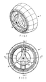
- An air vent 1 for a heating or air conditioning system comprises an air flow nozzle 3 having a part spherical outer wall 5 mounted within a housing 7 which is substantially circular in cross section about a longitudinal axis 9 and shaped to allow swivelling of the nozzle 3 within it.
- the nozzle 3 is mounted to the housing 7 via a gimbal member 11.
- the gimbal member 11 comprises two legs 13 with a web 15 extending between them, each leg 13 extending between the housing 7and the nozzle wall 5 in a longitudinal direction.
- Each leg 13 is pivotally attached to the housing 7 at diametrically opposite points 17 such that the gimbal member 11 may rotate about a first axis 19 with respect to the housing 7.
- the gimbal member 11 also comprises a tongue 21 extending from the web 15 to the first axis 19 between the pivot points 17 of the housing and being pivotally attached to the nozzle about a second axis 23 orthogonal to the first axis 19.
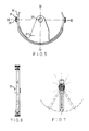
- the gimbal member is illustrated schematically only in figures 1 to 4 and is shown in detail in figures 5 to 7. As can be seen the legs 13 are arcuate and in fact the web and legs together define a semicircular rim.
- the gimbal member is generally planar and of a unitary moulded plastics unit.
- the tongue includes outwardly opposed bosses 25 which are used to pivotally mount the nozzle 3.
- the nozzle 3 includes two central parallel plates 27 including a circular bore into which the boss may be inserted. The nozzle ,may then be rotated about the bosses 25.
- the housing 7 includes a pair of diametrically opposed longitudinally extending grooves (not shown).
- the leg 13 includes an outwardly extending pin 29 onto which is pushfitted a U-shaped rotatable bracket 31.
- the bracket 31 may be slid into the groove in the housing and then when in this position the pin 29 may rotate with respect to the bracket 31 so that the gimbal member rotates with respect to the housing.
- the gimbal member is moulded from a resilient springy plastics so that the gimbal member bears against the housing for it to be firmly held in position.
- the air flow nozzle 3 includes means to vary the volume of air flow. These comprise a pair of rotatable shutters 33 each of which is a semicircular disc , and each including an arcuate guide 35.
- the nozzle is in two parts 37 and 39 which are mutually rotatable about the longitudinal axis 9.
- the outer part includes a depending pin (not shown) which engages the arcuate guide 35. Rotation of the outer part 37 moves the pin in the guide 35 to cause opening and closing of the shutters 33.
- the outer part 37 includes central member 39 at its hub which is coupled to its outer edge by three webs.
- the central member acts as a handle which can be grasped to allow rotation of the part 37.
- the nozzle also includes a cylindrical guide 41 which straightens the air flow.
Landscapes
- Physics & Mathematics (AREA)
- Thermal Sciences (AREA)
- Engineering & Computer Science (AREA)
- Mechanical Engineering (AREA)
- Air-Flow Control Members (AREA)
- Air-Conditioning For Vehicles (AREA)
Applications Claiming Priority (2)
| Application Number | Priority Date | Filing Date | Title |
|---|---|---|---|
| GBGB9626648.1A GB9626648D0 (en) | 1996-12-21 | 1996-12-21 | Improved air vent for a heating or air conditioning system |
| GB9626648 | 1996-12-21 |
Publications (2)
| Publication Number | Publication Date |
|---|---|
| EP0849104A2 true EP0849104A2 (fr) | 1998-06-24 |
| EP0849104A3 EP0849104A3 (fr) | 2000-07-05 |
Family
ID=10804867
Family Applications (1)
| Application Number | Title | Priority Date | Filing Date |
|---|---|---|---|
| EP97309997A Withdrawn EP0849104A3 (fr) | 1996-12-21 | 1997-12-11 | Buse d'aération améliorée pour système de chauffage ou de conditionnement d'air |
Country Status (3)
| Country | Link |
|---|---|
| EP (1) | EP0849104A3 (fr) |
| AU (1) | AU734932B2 (fr) |
| GB (1) | GB9626648D0 (fr) |
Cited By (3)
| Publication number | Priority date | Publication date | Assignee | Title |
|---|---|---|---|---|
| WO2010046253A1 (fr) * | 2008-10-21 | 2010-04-29 | Dr. Schneider Kunststoffwerke Gmbh | Buse d’air |
| CN105599568A (zh) * | 2014-11-18 | 2016-05-25 | 日本富拉司特株式会社 | 车辆用风向调整装置 |
| US9605866B2 (en) | 2013-05-16 | 2017-03-28 | Mahle International Gmbh | Air vent |
Citations (1)
| Publication number | Priority date | Publication date | Assignee | Title |
|---|---|---|---|---|
| GB1478226A (en) | 1974-03-21 | 1977-06-29 | Kammerer Gmbh M | Adjustable air outlet nozzle for air conditioning systems |
Family Cites Families (3)
| Publication number | Priority date | Publication date | Assignee | Title |
|---|---|---|---|---|
| IT1055617B (it) * | 1974-09-07 | 1982-01-11 | Daimler Benz Ag | Bicchetta per impianti di riscal damento e di ventilazione a bordo di autoveicoli |
| IT231376Y1 (it) * | 1993-04-30 | 1999-08-03 | Foggini Progetti | Bocchetta di erogazione dell'aria di climatizzazione per autoveicoli con griglia di diffusione orientabile. |
| GB2303440A (en) * | 1995-07-17 | 1997-02-19 | Ford Motor Co | Air vent for a motor vehicle |
-
1996
- 1996-12-21 GB GBGB9626648.1A patent/GB9626648D0/en active Pending
-
1997
- 1997-12-11 EP EP97309997A patent/EP0849104A3/fr not_active Withdrawn
- 1997-12-22 AU AU48543/97A patent/AU734932B2/en not_active Ceased
Patent Citations (1)
| Publication number | Priority date | Publication date | Assignee | Title |
|---|---|---|---|---|
| GB1478226A (en) | 1974-03-21 | 1977-06-29 | Kammerer Gmbh M | Adjustable air outlet nozzle for air conditioning systems |
Cited By (7)
| Publication number | Priority date | Publication date | Assignee | Title |
|---|---|---|---|---|
| WO2010046253A1 (fr) * | 2008-10-21 | 2010-04-29 | Dr. Schneider Kunststoffwerke Gmbh | Buse d’air |
| CN102186689A (zh) * | 2008-10-21 | 2011-09-14 | 施耐德博士塑料工厂有限公司 | 空气喷嘴 |
| CN102186689B (zh) * | 2008-10-21 | 2013-07-24 | 施耐德博士塑料工厂有限公司 | 空气喷嘴 |
| US8974273B2 (en) | 2008-10-21 | 2015-03-10 | Dr. Schneider Kunststoffwerke Gmbh | Air nozzle |
| US9605866B2 (en) | 2013-05-16 | 2017-03-28 | Mahle International Gmbh | Air vent |
| CN105599568A (zh) * | 2014-11-18 | 2016-05-25 | 日本富拉司特株式会社 | 车辆用风向调整装置 |
| CN105599568B (zh) * | 2014-11-18 | 2018-04-24 | 日本富拉司特株式会社 | 车辆用风向调整装置 |
Also Published As
| Publication number | Publication date |
|---|---|
| AU4854397A (en) | 1998-06-25 |
| AU734932B2 (en) | 2001-06-28 |
| GB9626648D0 (en) | 1997-02-12 |
| EP0849104A3 (fr) | 2000-07-05 |
Similar Documents
| Publication | Publication Date | Title |
|---|---|---|
| US5967891A (en) | Air vent for a heating or air conditioning system | |
| US5746651A (en) | Eyeball outlet assembly | |
| US20060052050A1 (en) | Air distribution apparatus | |
| CN107009850B (zh) | 出口设备 | |
| US5470276A (en) | Diffuser air outlet | |
| US5036753A (en) | Dual mode air outlet for air conditioning system | |
| US5947813A (en) | Double barrel air outlet assembly | |
| JPH0633850B2 (ja) | 機器の俯仰角度調整装置 | |
| US6176775B1 (en) | Fresh air nozzle device for a vehicle | |
| JPH0427045B2 (fr) | ||
| JPH09175154A (ja) | 回転扉の駆動機構 | |
| EP0622257A2 (fr) | Buse de délivrance d'air pour véhicules à moteur | |
| US6059653A (en) | Air outlet assembly having controllable effort generation | |
| US5569076A (en) | Oscillation fixed grille outlet | |
| US20020000307A1 (en) | Flow control device for gas stream | |
| EP0849104A2 (fr) | Buse d'aération améliorée pour système de chauffage ou de conditionnement d'air | |
| US4938122A (en) | Improved outlet assembly | |
| GB2094467A (en) | Ventilator Grille | |
| US4413551A (en) | Ventilator grill | |
| US20190126727A1 (en) | Air vent for a vehicle hvac system | |
| JP3581045B2 (ja) | フォグランプの取付け構造 | |
| EP4206009B1 (fr) | Diffuseur d'air pour un véhicule automobile | |
| KR100458077B1 (ko) | 차량용 에어 벤트 그릴 | |
| KR970031076A (ko) | 위성안테나의 위치조정장치(position controlling system of satellite antenna) | |
| GB2291134A (en) | Fan assembly |
Legal Events
| Date | Code | Title | Description |
|---|---|---|---|
| PUAI | Public reference made under article 153(3) epc to a published international application that has entered the european phase |
Free format text: ORIGINAL CODE: 0009012 |
|
| AK | Designated contracting states |
Kind code of ref document: A2 Designated state(s): DE FR GB |
|
| AX | Request for extension of the european patent |
Free format text: AL;LT;LV;MK;RO;SI |
|
| PUAL | Search report despatched |
Free format text: ORIGINAL CODE: 0009013 |
|
| AK | Designated contracting states |
Kind code of ref document: A3 Designated state(s): AT BE CH DE DK ES FI FR GB GR IE IT LI LU MC NL PT SE |
|
| AX | Request for extension of the european patent |
Free format text: AL;LT;LV;MK;RO;SI |
|
| 17P | Request for examination filed |
Effective date: 20001212 |
|
| AKX | Designation fees paid |
Free format text: DE FR GB |
|
| 17Q | First examination report despatched |
Effective date: 20020214 |
|
| STAA | Information on the status of an ep patent application or granted ep patent |
Free format text: STATUS: THE APPLICATION HAS BEEN WITHDRAWN |
|
| 18W | Application withdrawn |
Withdrawal date: 20020409 |