EP0849120A1 - Elektrischer Verbinder, insbesondere für Kraftfahrzeuge - Google Patents
Elektrischer Verbinder, insbesondere für Kraftfahrzeuge Download PDFInfo
- Publication number
- EP0849120A1 EP0849120A1 EP97117593A EP97117593A EP0849120A1 EP 0849120 A1 EP0849120 A1 EP 0849120A1 EP 97117593 A EP97117593 A EP 97117593A EP 97117593 A EP97117593 A EP 97117593A EP 0849120 A1 EP0849120 A1 EP 0849120A1
- Authority
- EP
- European Patent Office
- Prior art keywords
- conductor
- contact pin
- electrical
- strain relief
- electrical connector
- Prior art date
- Legal status (The legal status is an assumption and is not a legal conclusion. Google has not performed a legal analysis and makes no representation as to the accuracy of the status listed.)
- Granted
Links
Images

Classifications
-
- H—ELECTRICITY
- H01—ELECTRIC ELEMENTS
- H01R—ELECTRICALLY-CONDUCTIVE CONNECTIONS; STRUCTURAL ASSOCIATIONS OF A PLURALITY OF MUTUALLY-INSULATED ELECTRICAL CONNECTING ELEMENTS; COUPLING DEVICES; CURRENT COLLECTORS
- H01R12/00—Structural associations of a plurality of mutually-insulated electrical connecting elements, specially adapted for printed circuits, e.g. printed circuit boards [PCB], flat or ribbon cables, or like generally planar structures, e.g. terminal strips, terminal blocks; Coupling devices specially adapted for printed circuits, flat or ribbon cables, or like generally planar structures; Terminals specially adapted for contact with, or insertion into, printed circuits, flat or ribbon cables, or like generally planar structures
- H01R12/50—Fixed connections
- H01R12/59—Fixed connections for flexible printed circuits, flat or ribbon cables or like structures
- H01R12/65—Fixed connections for flexible printed circuits, flat or ribbon cables or like structures characterised by the terminal
- H01R12/67—Fixed connections for flexible printed circuits, flat or ribbon cables or like structures characterised by the terminal insulation penetrating terminals
-
- H—ELECTRICITY
- H01—ELECTRIC ELEMENTS
- H01R—ELECTRICALLY-CONDUCTIVE CONNECTIONS; STRUCTURAL ASSOCIATIONS OF A PLURALITY OF MUTUALLY-INSULATED ELECTRICAL CONNECTING ELEMENTS; COUPLING DEVICES; CURRENT COLLECTORS
- H01R12/00—Structural associations of a plurality of mutually-insulated electrical connecting elements, specially adapted for printed circuits, e.g. printed circuit boards [PCB], flat or ribbon cables, or like generally planar structures, e.g. terminal strips, terminal blocks; Coupling devices specially adapted for printed circuits, flat or ribbon cables, or like generally planar structures; Terminals specially adapted for contact with, or insertion into, printed circuits, flat or ribbon cables, or like generally planar structures
- H01R12/70—Coupling devices
- H01R12/77—Coupling devices for flexible printed circuits, flat or ribbon cables or like structures
- H01R12/771—Details
- H01R12/772—Strain relieving means
Definitions
- the invention relates to an electrical connector according to the preamble of claim 1, and a method for Establish an electrical connection according to the Preamble of claim 16.
- Electrical connectors are used in particular on the Motor vehicle sector increasingly diverse to manufacture electrical connections between the different Functional units used. With increasing spread the electronics in the motor vehicle, the demand increases reliable electrical connection paths to the different modules permanently and securely together connect. However, occur in the harsh environment various interferences, such as those in high Temperature fluctuations, strong vibrations, dust or Contamination, condensation and consequently corrosion can occur.
- the invention is therefore based on the object to avoid disadvantages described above and a inexpensive, easy to connect electrical Connector and a corresponding method of manufacture to provide an electrical connection. It should furthermore, with minimal assembly effort, a qualitative high quality and permanent electrical connection getting produced.
- solder connections are generally dispensed with.
- the contact pin can be used in one area take place, which is completely free of the flexible film or on the back of the conductor, for example is coated with the film.
- Areas of the front contact surface of the conductor with Film be coated as long as at least exposed Window of the conductor for contact with the contact pin remain.
- the contact pin penetrates the electrical conductor or the electrical conductor and a section of flexible film such that a substantially defined deflection of the Conductor and / or the flexible film is generated can predefined bending moments with these assigned Restoring forces are generated, at least partially within the elastic bending range of the conductor and / or the slide. This can be entered in the slide Vibrations or shocks are absorbed elastically without there is an interruption in the conductive connection. Especially in the area of digital signal transmission, where in Signal edges lying in the nanosecond range for the detection of Signal content used is really a temporal continuous connection is a great advantage.
- a mechanical device is advantageous Holding the conductor or foil together with the conductor, through which when driving the contact pin the conductor mechanically in a substantially annular region the recording is held. Includes this facility for Hold a shoulder at the side that is pressed in when the Contact pin is pressed down and to the side so that it is between the electrical conductor and the receptacle a press fit comes, vibratory forces can also be fully intercepted in the axial direction.
- one can simultaneously within the press fit closed volume can be created, which a Ingress of moisture or dirt and subsequent Corrosion permanent at the place of electrical contact excludes.
- the contact pin at Assembly through an opening assigned to it or Thinning in the film pressed so that this in assembled state in a funnel-shaped expanded Opening or opened thinning of the film sits.
- the contact pin ends conically or pointedly trained, this, similar to insulation displacement terminals, in alternative embodiment according to the invention also by any area of the elastic sheet with it embedded electrical conductor are driven so that both the film and the conductor are pierced and the corresponding dimensioning of the diameter of the Contact pin the desired defined power relationships generated between electrical conductor and contact pin.
- a second device for is also advantageous Strain relief provided, which is preferably in the slidable in the same direction as the contact pin is arranged, this second device for Strain relief a defined bending of the flexible film generated, which in a particularly preferred embodiment Deflection caused by 90 degrees. This will be in the plane vibrations or impulses running on the film almost not more transferred to their angled contacted end.
- connection to make the film L-shaped, so that the kink between the legs of the L to further lower the Transmission of mechanical forces leads.
- both the contact pin and the second device for Strain relief assigned a pre-assembled position in which are held by snapping or static friction and from which both in a common direction in their assembled position can be brought.
- an adhesive holder of the contact pin in a channel assigned to it within the dielectric Housing of the connector and a locking element on the tab of the second strain relief, which in its pre-assembled Position a resistance against unwanted locking provides.
- the electrical connector also has a side one Transport bracket on by moving his Housing is detachable, all assembly steps, namely removing the connector from its Mounting bracket, making an electrical contact encapsulating the resulting contact area, mechanical holding, closing a first and one second strain relief, attaching the electrical connector at its final assembly location and manufacture one electrical connection from the connector to a printed Printed circuit board performed in a single step will.
- the electrical contact between the connector and PCB or associated fitting can be done by Driving the contact pins into plated-through openings the printed circuit board or armature.
- FIG. 1 is the one according to the invention designated as a whole by 1 Connector in a perspective view obliquely from can be seen above.
- dielectric housing 2 Preferably by injection molding manufactured dielectric housing 2 has two in essential cylindrical channels 3, 4 for receiving one contact pin 5 each.
- the channels 3, 4 include at least one area with a defined diameter, within which the contact pin 5 with defined Stiction is kept.
- Holding devices extend below the housing 2 8, 9, 10, 11 to fix the position and secure it of the connector on a not shown in the figures Circuit board or receptacle, which the holding devices 8, 9, 10, 11 assigned openings.
- the longitudinal axes of the Holding devices 8, 9, 10, 11 also extend in the direction of movement indicated by arrow A, where the end of the holding devices 8 and 10 remote from the housing Latching means carries a latching connection with the not shown circuit board or associated recording can manufacture. This locking is done by a Insert the connector 1 in the arrow A designated direction in the assigned openings or Recordings made.
- FIGS 2 and 3 are further inventive Embodiments can be found, each 12 or 18th Contact pins 5 in their channels 3, 4 are to accommodate.
- the depression 12, which is a piece of the Recording 16 exposes an optical as well mechanical and / or electrical detection of the position of the flexible film 14 can be made at the stop 18.
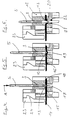
- FIGS. 4 to 6 in which is the process of making an electrical Contact and the closing of the first strain relief 13 with subsequent encapsulation of the contact area 14 is shown.
- the contact pin 5 When pressing the contact pin 5 in the direction of arrow A it hits with his lower conical or pointed end on the first Strain relief 13, which acts as an annular circumferential shoulder is formed, which the clear width of the channel 3rd narrowed.
- the flexible film 14 with the arranged therein electrical conductor 15 is in the slot-shaped receptacle 16 used such that an opening 17 in the conductor 15 and the Foil 14 is arranged concentrically under the channel 3.
- the film 14 When driving in the contact pin 5, the film 14 is then on the lower side of the ring shoulder 20, the one has defined rounding, so as to have a predefined, each on the flexible film 14 and the electrical To produce conductor 15 adapted deformation. Can also this avoids cracking and bending fractures and on the other hand it can have a defined elastic deflection are generated, the restoring forces within the Contact area 21 always a safe system of electrical conductor 15 on the contact pin 5 guaranteed.
- the lower end of the channel 3 has a constriction 22, a tight or sealing contact with the contact pin 5 ensures that the contact area 21 essentially is hermetically sealed to the outside.
- the tab 23 has a contact pin 5 facing in Cross-section T-shaped area, which also in a T-shaped recess of the housing 2 in the direction of the arrow A is arranged to be longitudinally displaceable.
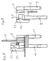
- the assembly tool moves with its flat lower one Surface in the direction of arrow A continues as shown in 7 and 8, the rider 23 in his lower latched position, in which the Latch 24 a substantially L-shaped in cross section Section 25 of the housing 2 engages behind.
- the flexible film 14 with the conductors 15 arranged therein In the assembled position of the Contact pin 5 and the tab 23 is the flexible film 14 with the conductors 15 arranged therein essentially Redirected 90 degrees, with vibration or shock within the film 14 and the conductor 15 practically no longer in the Interior of the housing 2 are transmitted.
- the flexible film 14 with the conductor 15 arranged therein an L-shaped Have section that due to its deflection by 90 Degrees again the transmission of vibrations or shocks significantly reduced.
- the assembly of the connector 1 on the flexible film 14 with the conductor 15 arranged therein can either step for Step or a single step
- the assembly can the static friction of the pin 5 within the channel 3 as well as when the contact pin 5 passes through the Foil 14 and the conductor 15 occurring forces so can be set that the housing 2 under the influence of a stepping down in the direction of arrow A.
- Assembly tool as long as in its transport bracket remains until the pins 5 at the opening 17 or thinned area 19, so the film 14 with the Fix conductor 15 within the receptacle 16, after which that Housing 2 out of the transport bracket downwards is moved that the holding devices 8, 9, 10, 11th through openings in a board or in an associated one Take recording, the holding devices 9, 11 with whose conical areas become a self-centering Perform adjustment.
Landscapes
- Coupling Device And Connection With Printed Circuit (AREA)
- Multi-Conductor Connections (AREA)
Abstract
Description
Es zeigen:
- Fig. 1
- eine perspektivische Ansicht einer ersten erfindungsgemäßen Auführungsform des elektrischen Verbinders,
- Fig. 2
- eine perspektivische Ansicht einer zweiten erfindungsgemäßen Ausführungsform des elektrischen Verbinders,
- Fig. 3
- eine perspektivische Ansicht einer dritten erfindungsgemäßen Ausführungsform des elektrischen Verbinders,
- Fig. 4
- einen Querschnitt im Bereich des Kontaktstiftes in dielektrischem Gehäuse verlaufend mit jeweils in vormontierter Stellung angeordnetem Kontaktstift und Reiter der zweiten Zugentlastung,
- Fig. 5
- einen Querschnitt gemäß Fig. 4, bei welchem die erste Zugentlastung in deren montierten bzw. zugentlastenden Zustand verbracht und anfänglicher elektrischer Kontakte zwischen dem Kontaktstift und dem Leiter hergestellt ist,
- Fig. 6
- einen Querschnitt gemäß Fig. 4, bei welchem der Kontaktstift vollständig durch den elektrischen Leiter hindurchgetreten und elektrischer Kontakt zum Leiter hergestellt ist,
- Fig. 7
- eine Querschnittsansicht in einer zu Fig. 4 parallel versetzten Ebene außerhalb des Kanals für den Kontaktstift,
- Fig. 8
- eine Seitenansicht des erfindungsgemäßen elektrischen Verbinders mit geschlossener zweiter Zugentlastung.
- 1
- elektrischer Verbinder
- 2
- dielektrisches Gehäuse
- 3, 4
- Kanal
- 5
- Kontaktstift
- 6,7
- Führungskanäle der Transporteinrichtung,
- 8,9,10,11
- Halteeinrichtungen
- 12
- Einsenkung
- 13
- erste Zugentlastung
- 14
- flexible Folie
- 15
- elektrischer Leiter
- 16
- Aufnahme
- 17
- Öffnung
- 18
- Anschlag
- 19
- verdünnter Bereich
- 20
- Ringschulter
- 21
- Kontaktbereich
- 22
- Verengung oder Dichtmittel
- 23
- Reiter
- 24
- Rastnase
- 25
- L-förmiger Abschnitt
Claims (23)
- Elektrischer Verbinder zum Herstellen einer Verbindung zu wenigstens einem im wesentlichen in einer flexiblen Folie angeordneten Leiter umfassend ein dielektrisches Gehäuse mit einer Aufnahme für das Einfügen der flexiblen Folie und des wenigstens einen Leiters,
gekennzeichnet durch
zumindest einen Kontaktstift (5) zum Herstellen eines elektrischen Kontakts zu dem wenigstens einen Leiter (15), wobei der Kontaktstift (5) auf den elektrischen Leiter (15) und/oder die flexible Folie (14) eine Kraft ausübt, die sowohl eine mechanische Anlage des Leiters (15) am Kontaktstift (5) als auch die Bereitstellung eines elektrischen Kontakts gewährt. - Elektrischer Verbinder nach Anspruch 1, dadurch gekennzeichnet, daß der Kontaktstift (5) den elektrischen Leiter (15), oder den elektrischen Leiter (15) und einen Abschnitt der flexiblen Folie (14), derart durchsetzt, daß eine im wesentlichen definierte Verbiegung des Leiters (15) und/oder der flexiblen Folie (14) erzeugt wird.
- Elektrischer Verbinder nach Anspruch 1 oder 2, dadurch gekennzeichnet, daß bei montiertem Kontaktstift (5) der Leiter (15) oder der Leiter (15) zusammen mit der flexiblen Folie (14) sowohl am Kontaktstift (5) als auch an einer Ringschulter (20) des dielektrischen Gehäuses (2) anliegen.
- Elektrischer Verbinder nach Anspruch 1, 2 oder 3, ferner gekennzeichnet durch eine erste, eine Zugentlastung bildende Einrichtung (13) zum mechanischen Halten des Leiters (15) oder der Folie (14) zusammen mit dem Leiter (15), durch welche beim Eintreiben des Kontaktstiftes (5) der Leiter (15) oder die Folie (14) zusammen mit dem Leiter (15) an einem im wesentlichen ringförmigen Bereich (13) mechanisch gehalten wird.
- Elektrischer Verbinder nach Anspruch 4, dadurch gekennzeichnet, daß die erste Einrichtung (13) zum Halten eine seitliche Schulter (13) umfaßt, die beim Eindrücken des mindestens einen Kontaktstiftes (5) so nach unten und zur Seite gedrückt wird, daß es zwischen dem elektrischen Leiter (15) und/oder der flexiblen Folie (14) zu einem Preßsitz innerhalb der Aufnahme (16) kommt.
- Elektrischer Verbinder nach einem der vorstehenden Ansprüche, dadurch gekennzeichnet, daß der Kontaktstift (5) im montierten Zustand durch eine diesem zugeordnete Öffnung (17) oder Ausdünnung (19) in der Folie (14) und im Leiter (15) hindurchtretend angeordnet ist.
- Elektrischer Verbinder nach einem der vorstehenden Ansprüche, dadurch gekennzeichnet, daß der Kontaktstift (5) zumindest an seinem dem elektrischen Leiter (15) vor der Montage zugewanten Ende konisch oder spitz verlaufend ausgebildet ist.
- Elektrischer Verbinder nach Anspruch 7, dadurch gekennzeichnet, daß der Kontaktstift (5) im montierten Zustand durch einen ohne vorherige Öffnung versehenen Leiterabschnitt (19) hindurchtretend angeordnet ist.
- Elektrischer Verbinder nach einem der vorstehenden Ansprüche, ferner gekennzeichnet durch eine zweite Einrichtung (23, 24) zum zur Zugentlastung.
- Elektrischer Verbinder nach Anspruch 9, dadurch gekennzeichnet, daß die zweite Einrichtung (23, 24) zur Zugentlastung in der gleichen Richtung verschieblich angeordnet ist, wie der Kontaktstift (5) und in der zugentlastenden Montagestellung eine definierte Verbiegung der flexiblen Folie (14) erzeugt.
- Elektrischer Verbinder nach Anspruch 9 oder 10, dadurch gekennzeichnet, daß die zweite Einrichtung (23, 24) zur Zugentlastung Rastelemente (24) aufweist, welche einen Reiter (23) der zweiten Zugentlastung in montierter zugentlastender Stellung halten.
- Elektrischer Verbinder nach einem der vorstehenden Ansprüche, dadurch gekennzeichnet, daß sowohl dem Kontaktstift (5) als auch der zweiten Einrichtung (23, 24) zur Zugentlastung eine vormontierte Stellung zugeordnet ist, aus welcher beide, die Zugentlastung (23, 24) und der Kontaktstift (5), in einer gemeinsamen Richtung in deren montierte Stellung bringbar sind.
- Elektrischer Verbinder nach einem der vorstehenden Ansprüche, gekennzeichnet durch einen Kanal (3) im dielektrischen Gehäuse (2) des Verbinders (1) zur Halterung des mindestens einen Kontaktstiftes (5) in Haftreibung zur Kanalwand.
- Elektrischer Verbinder nach einem der vorstehenden Ansprüche, ferner gekennzeichnet durch Halteeinrichtungen (9, 10, 11) zur Lagefixierung und dauerhaften Sicherung des Verbinders (1) an einer zugeordneten Platine, die an der Unterseite des Gehäuses des Verbinders mit deren Längsachse in Verschieberichtung des Kontaktstiftes (5) hervorragen und deren gehäusefernes Ende Rastmittel trägt.
- Elektrischer Verbinder nach einem der vorstehenden Ansprüche, ferner gekennzeichnet durch eine seitliche Transporthalterung (6, 7) am Verbinder, die durch eine Verschiebung des Gehäuses (2) des elektkrischen Verbinders (1) lösbar ist.
- Verfahren zur Herstellung einer elektrischen Verbindung zwischen einer einen elektrischen Leiter (15) führenden flexiblen Folie (14) und einem Verbinder (1), vorzugsweise zu einem Verbinder wie dieser in einem der vorstehenden Ansprüche definiert ist, gekennzeichnet durch:
das Eindrücken eines Kontaktstiftes (5) aus einer vormontierten Stellung in eine Montagestellung, wobei eine definierte Deformation in zumindest einen Bereich des elektkrischen Leiters (15) oder des elektrischen Leiters (15) mit der flexiblen Folie (14) eingebracht wird, wobei eine dauerhafte elektrische Verbindung zwischen Kontaktstift (5) und dem elektrischen Leiter (15) ausgebildet wird. - Verfahren zur Herstellung einer elektrischen Verbindung nach Anspruch 16, dadurch gekennzeichnet, daß während zumindest eines Teils des Einpressvorgangs des Kontaktstifts (5) eine erste eine Zugentlastung bildende Einrichtung (13) zum Halten aus deren vormontierter Stellung in deren montierte zugentlastende Stellung gebracht wird.
- Verfahren zur Herstellung einer elektrischen Verbindung nach Anspruch 16 oder 17, dadurch gekennzeichnet, daß während zumindest eines Teils des Einpressvorgangs eine zweite Zugentlastung (23, 24) aus deren vormontierter Stellung in deren montierte und verrastete zugentlastende Stellung gebracht wird.
- Verfahren zur Herstellung einer elektrischen Verbindung nach Anspruch 16, 17 oder 18, dadurch gekennzeichnet, daß der Kontaktstift (5) mit einem Ende aus dem dielektrischen Gehäuse heraus und in eine zugeordnete Öffnung in einer gedruckten Schaltungsplatine hineingeschoben wird.
- Verfahren zur Herstellung einer elektrischen Verbindung nach einem der Ansprüche von 16 bis 19, dadurch gekennzeichnet, daß der elektrische Verbinder vor, während oder nach einem der Verfahrensschritte der Ansprüche von 16 bis 19 aus einer Transporthalterung herausgeschoben wird.
- Verfahren zur Herstellung einer elektrischen Verbindung nach Anspruch 20, dadurch gekennzeichnet, daß der elektrische Verbinder (1) nach dem Herausschieben aus der Transporthalterung mit dessen Halteeinrichtungen (8, 9, 10, 11) zur Lagefixierung in zugeordnete Aufnahmeeinrichtungen zur verrasteten Halterung verbracht wird.
- Verfahren zur Herstellung einer elektrischen Verbindung nach einem der Ansprüche von 16 bis 21, dadurch gekennzeichnet, daß sämtliche Verfahrensschritte der Ansprüche von 16 bis 21 in einem einzigen Arbeitsschritt, insbesondere durch einen einzigen Verschiebevorgang durchgeführt werden.
- Verfahren zur Herstellung einer elektrischen Verbindung nach Anspruch 22, dadurch gekennzeichnet, daß die Haftreibungskoefizienten der längsverschieblichen Elemente des Verbinders (1) sowie die Kräfte des Kontatkstiftes (5) beim Durchtreten durch den Leiter (15) oder durch den Leiter (15) zusammen mit der Folie (14) während des Verschiebevorgangs einen definierter Ablauf der Verfahrensschrite ergibt.
Applications Claiming Priority (2)
| Application Number | Priority Date | Filing Date | Title |
|---|---|---|---|
| DE19646716 | 1996-11-12 | ||
| DE19646716A DE19646716B4 (de) | 1996-11-12 | 1996-11-12 | Elektrischer Verbinder, insbesondere für Kraftfahrzeuge |
Publications (2)
| Publication Number | Publication Date |
|---|---|
| EP0849120A1 true EP0849120A1 (de) | 1998-06-24 |
| EP0849120B1 EP0849120B1 (de) | 2006-08-02 |
Family
ID=7811423
Family Applications (1)
| Application Number | Title | Priority Date | Filing Date |
|---|---|---|---|
| EP97117593A Expired - Lifetime EP0849120B1 (de) | 1996-11-12 | 1997-10-10 | Elektrischer Verbinder, insbesondere für Kraftfahrzeuge |
Country Status (5)
| Country | Link |
|---|---|
| US (1) | US6299473B1 (de) |
| EP (1) | EP0849120B1 (de) |
| JP (1) | JP4033912B2 (de) |
| DE (2) | DE19646716B4 (de) |
| WO (1) | WO1998021069A1 (de) |
Cited By (1)
| Publication number | Priority date | Publication date | Assignee | Title |
|---|---|---|---|---|
| DE19957789A1 (de) * | 1999-12-01 | 2001-06-21 | Leoni Bordnetz Sys Gmbh & Co | Kontaktierungssystem für zwei Leiterplatten |
Families Citing this family (5)
| Publication number | Priority date | Publication date | Assignee | Title |
|---|---|---|---|---|
| US6634897B2 (en) | 2001-06-26 | 2003-10-21 | Delphi Technologies, Inc. | Twist-lock connector |
| US6857889B1 (en) | 2003-09-26 | 2005-02-22 | General Motors Corporation | Vehicle body to chassis connection and method |
| DE102008047457A1 (de) * | 2008-09-17 | 2010-03-25 | Saia-Burgess Oldenburg Gmbh & Co. Kg | Anordnung zum Verbinden wenigstens eines als Folie ausgebildeten elektrischen Leiters mit dem Pin eines Bauelementes |
| CN202262071U (zh) * | 2011-09-13 | 2012-05-30 | 鸿富锦精密工业(深圳)有限公司 | 柔性电路板 |
| EP2587592B1 (de) * | 2011-10-24 | 2016-03-30 | PHOENIX CONTACT GmbH & Co. KG | Mehrpoliger Kabelanschluss und Verfahren zur Herstellung eines mehrpoligen Kabelanschlusses |
Citations (5)
| Publication number | Priority date | Publication date | Assignee | Title |
|---|---|---|---|---|
| FR1548650A (de) * | 1966-10-28 | 1968-12-06 | ||
| GB2107135A (en) * | 1981-09-18 | 1983-04-20 | Molex Inc | Flat flexible cable termination |
| US4613196A (en) * | 1983-05-13 | 1986-09-23 | Jane G. Montgomery | Telephone cord terminating plug |
| EP0358404A2 (de) * | 1988-09-05 | 1990-03-14 | THOMAS & BETTS CORPORATION | Verbinder |
| US5125850A (en) * | 1991-11-27 | 1992-06-30 | Amp Incorporated | Strain relief for an electrical connector |
Family Cites Families (20)
| Publication number | Priority date | Publication date | Assignee | Title |
|---|---|---|---|---|
| US4012093A (en) * | 1971-08-25 | 1977-03-15 | The Deutsch Company Electronic Components Division | Connector arrangement for thin, deflectable conductors |
| US4006957A (en) * | 1974-09-25 | 1977-02-08 | Thomas & Betts Corporation | Connector |
| US4060295A (en) * | 1976-03-15 | 1977-11-29 | Molex Incorporated | Zero insertion force printed circuit board edge connector assembly |
| US4201436A (en) * | 1978-09-14 | 1980-05-06 | Sealectro Corporation | Miniature matrix assembly |
| SE413824B (sv) * | 1979-04-11 | 1980-06-23 | Welins Patenter | Anordning for forbindning av ett anslutningsdon |
| US4358177A (en) * | 1980-06-19 | 1982-11-09 | The Bendix Corporation | Strain relief clamp and assembly |
| US4503611A (en) * | 1981-09-18 | 1985-03-12 | Molex Incorporated | Method of making a circuit assembly |
| JPS61131382A (ja) * | 1984-11-29 | 1986-06-19 | アンプ インコ−ポレ−テツド | 電気コネクタ |
| GB8725475D0 (en) * | 1987-10-30 | 1987-12-02 | Amp Holland | Modular jack |
| FR2629954B1 (fr) * | 1988-04-08 | 1991-06-21 | Cetra Sarl | Connecteur auto-denudant |
| US4886942A (en) * | 1989-02-24 | 1989-12-12 | Molex Incorporated | Strain relief structure for connecting flat flexible cable to a circuit board |
| US4948379A (en) * | 1989-03-17 | 1990-08-14 | E. I. Du Pont De Nemours And Company | Separable, surface-mating electrical connector and assembly |
| DE8903656U1 (de) * | 1989-03-22 | 1989-07-06 | Siemens AG, 1000 Berlin und 8000 München | Steckverbindung für Flachbandkabel |
| DE4016890C2 (de) * | 1990-05-25 | 2002-10-24 | Elco Europ Gmbh | Befestigungsvorrichtung für die Sockel von Steckverbinderhälften auf Leiterplatten oder dergleichen |
| DE9100586U1 (de) * | 1991-01-19 | 1991-04-11 | Quante AG, 5600 Wuppertal | Druckstück für Durchdringungskontaktierung |
| US5199896A (en) * | 1991-07-29 | 1993-04-06 | Itt Corporation | Latchable p.c. board connector |
| DE4134321C1 (de) * | 1991-10-17 | 1993-04-01 | Stocko Metallwarenfabriken Henkels Und Sohn Gmbh & Co, 5600 Wuppertal, De | |
| US5344338A (en) * | 1992-03-04 | 1994-09-06 | Molex Incorporated | Strain relief structure for connecting flat flexible cable to a circuit board |
| JP3285242B2 (ja) * | 1993-01-25 | 2002-05-27 | 矢崎総業株式会社 | コネクタ構造 |
| JP2593430Y2 (ja) * | 1993-09-09 | 1999-04-12 | エスエムケイ株式会社 | Fpc/ffc用コネクタ |
-
1996
- 1996-11-12 DE DE19646716A patent/DE19646716B4/de not_active Expired - Fee Related
-
1997
- 1997-10-10 EP EP97117593A patent/EP0849120B1/de not_active Expired - Lifetime
- 1997-10-10 DE DE59712707T patent/DE59712707D1/de not_active Expired - Lifetime
- 1997-11-12 JP JP52204798A patent/JP4033912B2/ja not_active Expired - Fee Related
- 1997-11-12 WO PCT/DE1997/002652 patent/WO1998021069A1/de not_active Ceased
- 1997-12-11 US US09/308,083 patent/US6299473B1/en not_active Expired - Lifetime
Patent Citations (5)
| Publication number | Priority date | Publication date | Assignee | Title |
|---|---|---|---|---|
| FR1548650A (de) * | 1966-10-28 | 1968-12-06 | ||
| GB2107135A (en) * | 1981-09-18 | 1983-04-20 | Molex Inc | Flat flexible cable termination |
| US4613196A (en) * | 1983-05-13 | 1986-09-23 | Jane G. Montgomery | Telephone cord terminating plug |
| EP0358404A2 (de) * | 1988-09-05 | 1990-03-14 | THOMAS & BETTS CORPORATION | Verbinder |
| US5125850A (en) * | 1991-11-27 | 1992-06-30 | Amp Incorporated | Strain relief for an electrical connector |
Cited By (2)
| Publication number | Priority date | Publication date | Assignee | Title |
|---|---|---|---|---|
| DE19957789A1 (de) * | 1999-12-01 | 2001-06-21 | Leoni Bordnetz Sys Gmbh & Co | Kontaktierungssystem für zwei Leiterplatten |
| US6564450B2 (en) | 1999-12-01 | 2003-05-20 | Leoni Bordnetz Sys Gmbh & Co | Contacting-making system for two printed circuit boards |
Also Published As
| Publication number | Publication date |
|---|---|
| JP2001504978A (ja) | 2001-04-10 |
| WO1998021069A1 (de) | 1998-05-22 |
| JP4033912B2 (ja) | 2008-01-16 |
| EP0849120B1 (de) | 2006-08-02 |
| DE59712707D1 (de) | 2006-09-14 |
| DE19646716B4 (de) | 2008-08-28 |
| DE19646716A1 (de) | 1998-05-14 |
| US6299473B1 (en) | 2001-10-09 |
Similar Documents
| Publication | Publication Date | Title |
|---|---|---|
| DE102016120063B4 (de) | Steckverbindung | |
| DE4140403C2 (de) | Verfahren zur Montage eines Sensorkopfes für einen Magnetfeldgeber | |
| EP3057183B1 (de) | Gedichteter Stecker | |
| DE69904095T2 (de) | Elektrischer Steckverbinder zur Herstellung des Kontakts mit mindestens einer flachen Leiterfolie | |
| DE102010014144A1 (de) | Elektrische Anschlussklemme | |
| EP1966855A1 (de) | Kontaktierungssteckverbindung | |
| WO2003026076A1 (de) | Zugentlastung für einen steckverbinder in der kommunikations- und datentechnik | |
| DE69932636T2 (de) | Elektrischer Verbinder | |
| DE60003742T2 (de) | Kabelstecker in welchem zwei Kontakte einen Drahtkern eines Kabels zwischen sich befestigen | |
| DE102007009644B4 (de) | Mechatronische Baugruppe mit Steckverbindung | |
| DE4111054C2 (de) | ||
| EP1484822B1 (de) | Steckverbinder | |
| DE69800154T2 (de) | Elektrische Anschlussvorrichtung mit verbesserter Kontaktsicherheit | |
| DE10140153B4 (de) | Steckverbindung zum gleichzeitigen Verbinden mehrerer Koaxialkabel | |
| EP1750109A1 (de) | Drehmomentsensor und Verfahren zu dessen Herstellung | |
| EP0849120B1 (de) | Elektrischer Verbinder, insbesondere für Kraftfahrzeuge | |
| EP4430707A1 (de) | Kontaktträgereinrichtung, anschlussvorrichtung, betätiger, steckverbindereinsatz und montageverfahren sowie kabelanschlusssystem | |
| DE102017222809B4 (de) | Elektrischer Steckverbinder und Steckverbindung | |
| DE69401118T2 (de) | Elektrischer Kabel für Verbinder sowie Produktionsverfahren und Einrichtung | |
| WO2000045468A1 (de) | Vorrichtung zur abisolierfreien kontaktierung eines flachkabels | |
| DE102019111847A1 (de) | Weiblicher Einpress-Steckverbinder, Verfahren zur Herstellung eines solchen Steckverbinders, Einpress-Steckverbinder-System und Baugruppe mit einem solchen Einpress-Steckverbinder | |
| DE69113669T2 (de) | Anordnung zum Fixieren eines Koaxialkabels und zum Verbinden mit der Masse einer gedruckten Leiterplatte. | |
| DE202017107625U1 (de) | Elektrischer Steckverbinder | |
| EP0905818A2 (de) | HF-Steckverbindungssystem und Verfahren zur Montage des HF-Steckverbindungssystems | |
| DE102006020045B4 (de) | Zwischenstecker und Verfahren zur Herstellung eines Zwischensteckers |
Legal Events
| Date | Code | Title | Description |
|---|---|---|---|
| PUAI | Public reference made under article 153(3) epc to a published international application that has entered the european phase |
Free format text: ORIGINAL CODE: 0009012 |
|
| AK | Designated contracting states |
Kind code of ref document: A1 Designated state(s): DE ES FR GB IT |
|
| 17P | Request for examination filed |
Effective date: 19981126 |
|
| AKX | Designation fees paid |
Free format text: DE ES FR GB IT |
|
| RBV | Designated contracting states (corrected) |
Designated state(s): DE ES FR GB IT |
|
| 17Q | First examination report despatched |
Effective date: 20020703 |
|
| RTI1 | Title (correction) |
Free format text: ELECTRICAL CONNECTOR AND METHOD FOR PRODUCING AN ELECTRICAL CONNECTION |
|
| GRAP | Despatch of communication of intention to grant a patent |
Free format text: ORIGINAL CODE: EPIDOSNIGR1 |
|
| RIC1 | Information provided on ipc code assigned before grant |
Ipc: B60R 16/02 19800101ALI20051129BHEP Ipc: H01R 12/38 00000000ALI20051129BHEP Ipc: H01R 12/24 00000000ALI20051129BHEP Ipc: H01R 12/10 00000000AFI20051129BHEP |
|
| RTI1 | Title (correction) |
Free format text: ELECTRIC CONNECTOR FOR VEHICLES |
|
| GRAS | Grant fee paid |
Free format text: ORIGINAL CODE: EPIDOSNIGR3 |
|
| GRAA | (expected) grant |
Free format text: ORIGINAL CODE: 0009210 |
|
| AK | Designated contracting states |
Kind code of ref document: B1 Designated state(s): DE ES FR GB IT |
|
| PG25 | Lapsed in a contracting state [announced via postgrant information from national office to epo] |
Ref country code: IT Free format text: LAPSE BECAUSE OF FAILURE TO SUBMIT A TRANSLATION OF THE DESCRIPTION OR TO PAY THE FEE WITHIN THE PRESCRIBED TIME-LIMIT;WARNING: LAPSES OF ITALIAN PATENTS WITH EFFECTIVE DATE BEFORE 2007 MAY HAVE OCCURRED AT ANY TIME BEFORE 2007. THE CORRECT EFFECTIVE DATE MAY BE DIFFERENT FROM THE ONE RECORDED. Effective date: 20060802 |
|
| REG | Reference to a national code |
Ref country code: GB Ref legal event code: FG4D Free format text: NOT ENGLISH |
|
| REF | Corresponds to: |
Ref document number: 59712707 Country of ref document: DE Date of ref document: 20060914 Kind code of ref document: P |
|
| GBT | Gb: translation of ep patent filed (gb section 77(6)(a)/1977) |
Effective date: 20060913 |
|
| PG25 | Lapsed in a contracting state [announced via postgrant information from national office to epo] |
Ref country code: ES Free format text: LAPSE BECAUSE OF FAILURE TO SUBMIT A TRANSLATION OF THE DESCRIPTION OR TO PAY THE FEE WITHIN THE PRESCRIBED TIME-LIMIT Effective date: 20061113 |
|
| ET | Fr: translation filed | ||
| PLBE | No opposition filed within time limit |
Free format text: ORIGINAL CODE: 0009261 |
|
| STAA | Information on the status of an ep patent application or granted ep patent |
Free format text: STATUS: NO OPPOSITION FILED WITHIN TIME LIMIT |
|
| 26N | No opposition filed |
Effective date: 20070503 |
|
| PGFP | Annual fee paid to national office [announced via postgrant information from national office to epo] |
Ref country code: IT Payment date: 20081029 Year of fee payment: 12 |
|
| PGFP | Annual fee paid to national office [announced via postgrant information from national office to epo] |
Ref country code: GB Payment date: 20081029 Year of fee payment: 12 |
|
| PG25 | Lapsed in a contracting state [announced via postgrant information from national office to epo] |
Ref country code: GB Free format text: LAPSE BECAUSE OF NON-PAYMENT OF DUE FEES Effective date: 20091010 |
|
| PGFP | Annual fee paid to national office [announced via postgrant information from national office to epo] |
Ref country code: FR Payment date: 20101105 Year of fee payment: 14 |
|
| PG25 | Lapsed in a contracting state [announced via postgrant information from national office to epo] |
Ref country code: IT Free format text: LAPSE BECAUSE OF NON-PAYMENT OF DUE FEES Effective date: 20091010 |
|
| REG | Reference to a national code |
Ref country code: FR Ref legal event code: ST Effective date: 20120629 |
|
| PG25 | Lapsed in a contracting state [announced via postgrant information from national office to epo] |
Ref country code: FR Free format text: LAPSE BECAUSE OF NON-PAYMENT OF DUE FEES Effective date: 20111102 |
|
| PGFP | Annual fee paid to national office [announced via postgrant information from national office to epo] |
Ref country code: DE Payment date: 20121029 Year of fee payment: 16 |
|
| PG25 | Lapsed in a contracting state [announced via postgrant information from national office to epo] |
Ref country code: DE Free format text: LAPSE BECAUSE OF NON-PAYMENT OF DUE FEES Effective date: 20140501 |
|
| REG | Reference to a national code |
Ref country code: DE Ref legal event code: R119 Ref document number: 59712707 Country of ref document: DE Effective date: 20140501 |