EP0849143A2 - Federgespannter, mechanischer Expander mit festgelegter Vorspannung und konstanter Referenz- Position - Google Patents
Federgespannter, mechanischer Expander mit festgelegter Vorspannung und konstanter Referenz- Position Download PDFInfo
- Publication number
- EP0849143A2 EP0849143A2 EP97121552A EP97121552A EP0849143A2 EP 0849143 A2 EP0849143 A2 EP 0849143A2 EP 97121552 A EP97121552 A EP 97121552A EP 97121552 A EP97121552 A EP 97121552A EP 0849143 A2 EP0849143 A2 EP 0849143A2
- Authority
- EP
- European Patent Office
- Prior art keywords
- shaft
- respect
- cylinder
- tubular
- spring
- Prior art date
- Legal status (The legal status is an assumption and is not a legal conclusion. Google has not performed a legal analysis and makes no representation as to the accuracy of the status listed.)
- Granted
Links
Images


Classifications
-
- B—PERFORMING OPERATIONS; TRANSPORTING
- B62—LAND VEHICLES FOR TRAVELLING OTHERWISE THAN ON RAILS
- B62D—MOTOR VEHICLES; TRAILERS
- B62D7/00—Steering linkage; Stub axles or their mountings
- B62D7/06—Steering linkage; Stub axles or their mountings for individually-pivoted wheels, e.g. on king-pins
- B62D7/14—Steering linkage; Stub axles or their mountings for individually-pivoted wheels, e.g. on king-pins the pivotal axes being situated in more than one plane transverse to the longitudinal centre line of the vehicle, e.g. all-wheel steering
- B62D7/148—Steering linkage; Stub axles or their mountings for individually-pivoted wheels, e.g. on king-pins the pivotal axes being situated in more than one plane transverse to the longitudinal centre line of the vehicle, e.g. all-wheel steering provided with safety devices
-
- F—MECHANICAL ENGINEERING; LIGHTING; HEATING; WEAPONS; BLASTING
- F16—ENGINEERING ELEMENTS AND UNITS; GENERAL MEASURES FOR PRODUCING AND MAINTAINING EFFECTIVE FUNCTIONING OF MACHINES OR INSTALLATIONS; THERMAL INSULATION IN GENERAL
- F16F—SPRINGS; SHOCK-ABSORBERS; MEANS FOR DAMPING VIBRATION
- F16F3/00—Spring units consisting of several springs, e.g. for obtaining a desired spring characteristic
- F16F3/02—Spring units consisting of several springs, e.g. for obtaining a desired spring characteristic with springs made of steel or of other material having low internal friction
- F16F3/04—Spring units consisting of several springs, e.g. for obtaining a desired spring characteristic with springs made of steel or of other material having low internal friction composed only of wound springs
Definitions
- the present invention relates to a spring-loaded mechanical expander with preset preloading and constant reference position.
- the expression "mechanical expander” is used to designate devices which are interposed between an actuation element and an actuated element and allow to absorb the action (force or moment) of the actuation element if the actuated element is blocked, or to transmit a force or moment which is lower than a preset value.
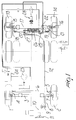
- FIG. 1 of the accompanying drawings is a diagram of a steering system of a motor vehicle which has a front axle and a rear axle, both of which have steered wheels.
- the reference numerals 1 and 2 designate the two leading wheels of a motor vehicle which has power-assisted steering on the front axle.
- the wheels 1 and 2 are mounted so that they can be orientated on an axle 3 and can be steered by means of a four-sided articulated linkage system which is composed of two arms 4, 5 which are mutually connected by a transverse bar 6.
- a second arm 7 is rigidly coupled to the arm 5 and is connected, by means of a traction element 8, to the actuation lever 9 of a hydraulic steering system, generally designated by the reference numeral 10, which is capable of producing the oscillation of the lever 9 in one direction or the other when the steering wheels 11 is operated.
- a flexible cable 12 is articulated in a median point of the lever 9 and actuates the steering of the wheels 13, 14 of the rear axle.
- the wheels 13, 14 can rotate about respective pivots 15, 16 which are articulated to the opposite ends of the beam 17 that constitutes the rear axle.
- Two respective arms 18, 19 are rigidly coupled to the pivots 15, 16 and are mutually connected by a bar 20 which forms the four-sided steering linkage system together with said arms.
- a further arm 21 is rigidly coupled to the pivot 16 above the arm 19.
- a jack 22 acts between said arm 21 and the beam 17 and its chambers can be connected to a pump 23 for feeding pressurized oil and to the discharge 24 by means of a distributor 25.
- the distributor 25 is controlled, by means of a rod 26 and a lever 27 which is pivoted in a rocker-like manner, by the flexible cable 12. In this manner, by actuating the steering wheel 12 in one direction or the other, a slide valve of the distributor 25 is moved in the corresponding steering direction of the rear wheels 13, 14.
- the reference numeral 28 designates a device for locking the rear wheels, which is activated when one wishes the rear wheels to remain orientated in the straight-line travel direction.
- a device of this kind is described for example in Italian patent applications no. BO92A000327, BO95A000029 and European Patent Applications No. 95117082.8, 97100704.2 and 97118171.4.
- the rod 26 is constituted by a linear expander, i.e., by an element which is adapted to shorten and extend in order to allow the sliding of the cable 12.
- a normal linear expander of the elastic type would not allow to achieve a constant position to which the strokes of the slide valve 25 could be referred in order to precisely and repeatably actuate the steering of the rear wheels.
- the aim of the present invention is therefore to provide an expander which is structured so as to behave like a rigid transmission element up to a preset value of the transmitted force and like an elastic element when said value is exceeded.
- an object of the present invention is to provide an expander which, while using the same inventive concept, can be provided as a linear expander or as a rotary expander according to the requirements.
- the expander 26 of the example of figure 1 is constituted by an outer cylinder 29 which is closed at one end by an end plate 30 provided with a threaded stem 31 for coupling to the slide valve of the distributor 25.
- a bush 32 is screwed into the cylinder 29 and slidingly supports a tubular stem 33, the outer wall of which is spaced from the inner wall of the cylinder 29 so as to form an interspace 34.
- the tubular stem 33 has, at the end located outside the cylinder 29, a threaded stem 35 for coupling to an arm of the lever 27.
- a collar 36 which forms a seat 37 for guiding a rod 38 which lies coaxially within the tubular stem 33 and delimits, together with said stem, a tubular interspace 39 located inside the interspace 34.
- Two bolts 40, 41 are screwed to the opposite ends of the rod 38; their heads for respective shoulders.
- the head of the bolt 40 is meant to abut against the collar 36, while the head of the bolt 41 acts as resting element for a ring 42 which is guided in the cylinder 29 externally and on the rod 38 internally.
- the ring 42 is kept rested on the head of the bolt 41 and on the end plate 30 by means of a pair of mutually concentric springs 43, 44, the opposite ends of which abut respectively against the collar 36 and against the edge of the bush 32.
- FIG. 6 An example of such a rotary expander is shown in figure 6 in an application to a vehicle of the type described above with reference to figure 1 and whereof identical or functionally similar components have been designated by the same reference numerals in figure 6.
- the rotary expander is generally designated by the reference numeral 45 and comprises a first radial lever 46, which is connected to the flexible cable 12, and a second radial lever 47, which is connected to the slide valve of the distributor 25 by means of a traction element 48.
- the radial arms 46 and 47 maintain their constant angular position up to a certain value of the traction force applied by the flexible cable 12.
- the arm 46 can perform angular strokes in both directions of rotation with respect to the intermediate position.
- the rotary expander 45 is constituted by a bush 49 fixed to a bracket 49a which is rigidly coupled to the beam 17 of the rear axle.
- a shaft 51 is rotatably supported in the bush 49 by means of bearings 50 and forms a flange 52 which lies outside the bush 49.
- a cylindrical body 53 is centered and fixed in the flange 52 and has, at the end that lies opposite to the flange 52, a tubular axial extension 54 for the centering of the lever 47, which is fixed frontally to the body 53.
- the shaft 51 lies axially inside the body 53 and supports, adjacent to flange 52, by means of a bearing 55, a disk 56. Proximate to the bearing 55, the shaft 51 has two diametrically opposite chamfers which form a diametrical key 57.
- the shaft 51 extends, from said key 57, with an axial tang 58.
- a hollow shaft 61 is supported so that it can rotate on the tang 58 and in the tubular extension 54 of the body 53 by means of bearings 59, 60 and is provided with a peripheral collar 62.
- Said hollow shaft 61 has an end which protrudes outside the tubular extension 54 and to which the lever 46 is fixed frontally.
- the hollow shaft 61 has two diametrically opposite axial teeth 63, between which the key 57 lies.
- the key 57 and the axial teeth 63 have the same thickness and are inserted in an opening 64 of the disk 56 which is shaped like an hourglass.
- the opening 64 is in fact composed of two substantially triangular slots which are mutually opposite with respect to the axis A of the shaft 61 and mutually intersect in order to allow the insertion of the key 57 at the center and allow said key and the teeth 63 to perform angular strokes inside the opening 64.
- a tubular chamber 65 is formed between the body 53 and the hollow shaft 61 and is delimited axially on one side by the disk 56 and on the opposite side by the collar 62 and by a shoulder 66 of the body 53.
- Two concentric springs 67, 68 are accommodated in the chamber 65: the opposite ends of the outer spring 68 are rigidly coupled in the shoulder 66 of the body 53 and in the disk 56, while the opposite ends of the inner spring 67 are rigidly coupled in the collar 62 and in the disk 56.
- the springs 67, 68 keep the teeth 63 and the key 57 in abutment against the same sides of the opening 64, as shown in figure 4.
- the spring 68 by acting between the body 53 and the disk 56, in fact actuates said disk into abutment against the key 57.
- the spring 67 by acting between the disk 56 and the hollow shaft 61, actuates the axial teeth 63 into abutment against the disk 65.
- the thrust with which the teeth 62 and the key 57 press against the sides of the opening 64 is determined by the preloading of the springs 67, 68.
- the levers 46, 47 maintain their angular position and the expander 45 behaves like a two-arm lever.
- the action of the cable 12 in one direction or the other causes the simple rotation of the body 53 with respect to the shaft 61, allowing the lever 46 to perform angular strokes with respect to the lever 47.
Landscapes
- Engineering & Computer Science (AREA)
- Mechanical Engineering (AREA)
- General Engineering & Computer Science (AREA)
- Chemical & Material Sciences (AREA)
- Combustion & Propulsion (AREA)
- Transportation (AREA)
- Springs (AREA)
- Steering Controls (AREA)
- Valve-Gear Or Valve Arrangements (AREA)
- Pistons, Piston Rings, And Cylinders (AREA)
- Actuator (AREA)
- Steering-Linkage Mechanisms And Four-Wheel Steering (AREA)
Applications Claiming Priority (2)
| Application Number | Priority Date | Filing Date | Title |
|---|---|---|---|
| ITBO960665 | 1996-12-17 | ||
| IT96BO000665A IT1287596B1 (it) | 1996-12-17 | 1996-12-17 | Espansore meccanico a molla con precarica predeterminata avente costante posizione di riferimento |
Publications (3)
| Publication Number | Publication Date |
|---|---|
| EP0849143A2 true EP0849143A2 (de) | 1998-06-24 |
| EP0849143A3 EP0849143A3 (de) | 1999-08-25 |
| EP0849143B1 EP0849143B1 (de) | 2003-05-14 |
Family
ID=11341794
Family Applications (1)
| Application Number | Title | Priority Date | Filing Date |
|---|---|---|---|
| EP97121552A Expired - Lifetime EP0849143B1 (de) | 1996-12-17 | 1997-12-08 | Federgespannter, mechanischer Expander mit festgelegter Vorspannung und konstanter Referenz- Position |
Country Status (3)
| Country | Link |
|---|---|
| EP (1) | EP0849143B1 (de) |
| DE (1) | DE69721954T2 (de) |
| IT (1) | IT1287596B1 (de) |
Cited By (1)
| Publication number | Priority date | Publication date | Assignee | Title |
|---|---|---|---|---|
| CN107962337A (zh) * | 2018-01-26 | 2018-04-27 | 陈烁 | 易解脱撑杆 |
Family Cites Families (1)
| Publication number | Priority date | Publication date | Assignee | Title |
|---|---|---|---|---|
| GB781403A (en) * | 1954-10-01 | 1957-08-21 | Wheaton Brass Works | Improvements in spring counterbalanced swing joint supported conduit or like arm |
-
1996
- 1996-12-17 IT IT96BO000665A patent/IT1287596B1/it active IP Right Grant
-
1997
- 1997-12-08 DE DE69721954T patent/DE69721954T2/de not_active Expired - Lifetime
- 1997-12-08 EP EP97121552A patent/EP0849143B1/de not_active Expired - Lifetime
Non-Patent Citations (1)
| Title |
|---|
| None |
Cited By (1)
| Publication number | Priority date | Publication date | Assignee | Title |
|---|---|---|---|---|
| CN107962337A (zh) * | 2018-01-26 | 2018-04-27 | 陈烁 | 易解脱撑杆 |
Also Published As
| Publication number | Publication date |
|---|---|
| EP0849143B1 (de) | 2003-05-14 |
| ITBO960665A0 (it) | 1996-12-17 |
| ITBO960665A1 (it) | 1998-06-17 |
| DE69721954T2 (de) | 2004-05-19 |
| DE69721954D1 (de) | 2003-06-18 |
| EP0849143A3 (de) | 1999-08-25 |
| IT1287596B1 (it) | 1998-08-06 |
Similar Documents
| Publication | Publication Date | Title |
|---|---|---|
| EP0154991B1 (de) | Vierradlenkungssystem für Fahrzeuge | |
| US5975573A (en) | Steering system | |
| US3075501A (en) | Power steering mechanism | |
| US4279323A (en) | Power steering device for wheeled vehicles | |
| KR890002491B1 (ko) | 스티어링 기어 | |
| EP0067572B1 (de) | Servolenkungseinrichtung | |
| US5664646A (en) | Disc brake, especially for vehicles | |
| US3218937A (en) | Variable ratio power steering gear | |
| US5571238A (en) | Centering device, especially for steering valves | |
| JPS6222B2 (de) | ||
| EP0849143B1 (de) | Federgespannter, mechanischer Expander mit festgelegter Vorspannung und konstanter Referenz- Position | |
| US5078018A (en) | Rear wheel steering mechanism for motor vehicle | |
| US4417501A (en) | Steering booster system | |
| US4483237A (en) | Steering gear with auxiliary power support | |
| US4421010A (en) | Steering gear for motor vehicles | |
| JP2001520959A (ja) | 自動車の動力舵取り装置のロータリ・シフト弁 | |
| GB2165502A (en) | A power-assisted steering gear | |
| JP3109920B2 (ja) | 操舵装置 | |
| US5348110A (en) | Device for actuating the control valve of a hydraulic power steering system | |
| US4263816A (en) | Steering gear assemblies | |
| EP0331120B1 (de) | Fahrzeug-Lenksystem | |
| JPH0382674A (ja) | 液圧補助力制御装置 | |
| JP4055001B2 (ja) | 減速比可変式動力舵取り装置 | |
| US6253657B1 (en) | Steering apparatus | |
| GB855579A (en) | Improvements in or relating to servo-steering devices for motor vehicles |
Legal Events
| Date | Code | Title | Description |
|---|---|---|---|
| PUAI | Public reference made under article 153(3) epc to a published international application that has entered the european phase |
Free format text: ORIGINAL CODE: 0009012 |
|
| AK | Designated contracting states |
Kind code of ref document: A2 Designated state(s): DE ES FR GB |
|
| AX | Request for extension of the european patent |
Free format text: AL;LT;LV;MK;RO;SI |
|
| PUAL | Search report despatched |
Free format text: ORIGINAL CODE: 0009013 |
|
| AK | Designated contracting states |
Kind code of ref document: A3 Designated state(s): AT BE CH DE DK ES FI FR GB GR IE IT LI LU MC NL PT SE |
|
| AX | Request for extension of the european patent |
Free format text: AL;LT;LV;MK;RO;SI |
|
| RIC1 | Information provided on ipc code assigned before grant |
Free format text: 6B 62D 7/14 A, 6F 16F 3/04 B |
|
| 17P | Request for examination filed |
Effective date: 20000126 |
|
| AKX | Designation fees paid |
Free format text: DE ES FR GB |
|
| GRAH | Despatch of communication of intention to grant a patent |
Free format text: ORIGINAL CODE: EPIDOS IGRA |
|
| GRAH | Despatch of communication of intention to grant a patent |
Free format text: ORIGINAL CODE: EPIDOS IGRA |
|
| GRAA | (expected) grant |
Free format text: ORIGINAL CODE: 0009210 |
|
| AK | Designated contracting states |
Designated state(s): DE ES FR GB |
|
| REG | Reference to a national code |
Ref country code: GB Ref legal event code: FG4D |
|
| REF | Corresponds to: |
Ref document number: 69721954 Country of ref document: DE Date of ref document: 20030618 Kind code of ref document: P |
|
| PG25 | Lapsed in a contracting state [announced via postgrant information from national office to epo] |
Ref country code: ES Free format text: LAPSE BECAUSE OF FAILURE TO SUBMIT A TRANSLATION OF THE DESCRIPTION OR TO PAY THE FEE WITHIN THE PRESCRIBED TIME-LIMIT Effective date: 20030825 |
|
| ET | Fr: translation filed | ||
| PG25 | Lapsed in a contracting state [announced via postgrant information from national office to epo] |
Ref country code: GB Free format text: LAPSE BECAUSE OF NON-PAYMENT OF DUE FEES Effective date: 20031208 |
|
| PLBE | No opposition filed within time limit |
Free format text: ORIGINAL CODE: 0009261 |
|
| STAA | Information on the status of an ep patent application or granted ep patent |
Free format text: STATUS: NO OPPOSITION FILED WITHIN TIME LIMIT |
|
| 26N | No opposition filed |
Effective date: 20040217 |
|
| GBPC | Gb: european patent ceased through non-payment of renewal fee |
Effective date: 20031208 |
|
| REG | Reference to a national code |
Ref country code: DE Ref legal event code: R082 Ref document number: 69721954 Country of ref document: DE Representative=s name: SCHAUMBURG UND PARTNER PATENTANWAELTE MBB, DE Ref country code: DE Ref legal event code: R082 Ref document number: 69721954 Country of ref document: DE Representative=s name: SCHAUMBURG & PARTNER PATENTANWAELTE MBB, DE Ref country code: DE Ref legal event code: R082 Ref document number: 69721954 Country of ref document: DE Representative=s name: SCHAUMBURG & PARTNER PATENTANWAELTE GBR, DE |
|
| REG | Reference to a national code |
Ref country code: FR Ref legal event code: PLFP Year of fee payment: 19 |
|
| REG | Reference to a national code |
Ref country code: FR Ref legal event code: PLFP Year of fee payment: 20 |
|
| PGFP | Annual fee paid to national office [announced via postgrant information from national office to epo] |
Ref country code: DE Payment date: 20161207 Year of fee payment: 20 |
|
| PGFP | Annual fee paid to national office [announced via postgrant information from national office to epo] |
Ref country code: FR Payment date: 20161205 Year of fee payment: 20 |
|
| REG | Reference to a national code |
Ref country code: DE Ref legal event code: R071 Ref document number: 69721954 Country of ref document: DE |