EP0849148A2 - Anti- Diebstahlvorrichtung für Fahrrad - Google Patents
Anti- Diebstahlvorrichtung für Fahrrad Download PDFInfo
- Publication number
- EP0849148A2 EP0849148A2 EP19970121971 EP97121971A EP0849148A2 EP 0849148 A2 EP0849148 A2 EP 0849148A2 EP 19970121971 EP19970121971 EP 19970121971 EP 97121971 A EP97121971 A EP 97121971A EP 0849148 A2 EP0849148 A2 EP 0849148A2
- Authority
- EP
- European Patent Office
- Prior art keywords
- bicycle
- saddle
- state
- supported
- bicycle frame
- Prior art date
- Legal status (The legal status is an assumption and is not a legal conclusion. Google has not performed a legal analysis and makes no representation as to the accuracy of the status listed.)
- Withdrawn
Links
Images


Classifications
-
- B—PERFORMING OPERATIONS; TRANSPORTING
- B62—LAND VEHICLES FOR TRAVELLING OTHERWISE THAN ON RAILS
- B62K—CYCLES; CYCLE FRAMES; CYCLE STEERING DEVICES; RIDER-OPERATED TERMINAL CONTROLS SPECIALLY ADAPTED FOR CYCLES; CYCLE AXLE SUSPENSIONS; CYCLE SIDECARS, FORECARS, OR THE LIKE
- B62K19/00—Cycle frames
- B62K19/30—Frame parts shaped to receive other cycle parts or accessories
- B62K19/36—Frame parts shaped to receive other cycle parts or accessories for attaching saddle pillars, e.g. adjustable during ride
-
- B—PERFORMING OPERATIONS; TRANSPORTING
- B62—LAND VEHICLES FOR TRAVELLING OTHERWISE THAN ON RAILS
- B62H—CYCLE STANDS; SUPPORTS OR HOLDERS FOR PARKING OR STORING CYCLES; APPLIANCES PREVENTING OR INDICATING UNAUTHORIZED USE OR THEFT OF CYCLES; LOCKS INTEGRAL WITH CYCLES; DEVICES FOR LEARNING TO RIDE CYCLES
- B62H1/00—Supports or stands forming part of or attached to cycles
- B62H1/02—Articulated stands, e.g. in the shape of hinged arms
-
- B—PERFORMING OPERATIONS; TRANSPORTING
- B62—LAND VEHICLES FOR TRAVELLING OTHERWISE THAN ON RAILS
- B62H—CYCLE STANDS; SUPPORTS OR HOLDERS FOR PARKING OR STORING CYCLES; APPLIANCES PREVENTING OR INDICATING UNAUTHORIZED USE OR THEFT OF CYCLES; LOCKS INTEGRAL WITH CYCLES; DEVICES FOR LEARNING TO RIDE CYCLES
- B62H5/00—Appliances preventing or indicating unauthorised use or theft of cycles; Locks integral with cycles
- B62H5/005—Appliances preventing or indicating unauthorised use or theft of cycles; Locks integral with cycles acting on the stand
-
- B—PERFORMING OPERATIONS; TRANSPORTING
- B62—LAND VEHICLES FOR TRAVELLING OTHERWISE THAN ON RAILS
- B62H—CYCLE STANDS; SUPPORTS OR HOLDERS FOR PARKING OR STORING CYCLES; APPLIANCES PREVENTING OR INDICATING UNAUTHORIZED USE OR THEFT OF CYCLES; LOCKS INTEGRAL WITH CYCLES; DEVICES FOR LEARNING TO RIDE CYCLES
- B62H5/00—Appliances preventing or indicating unauthorised use or theft of cycles; Locks integral with cycles
- B62H5/006—Appliances preventing or indicating unauthorised use or theft of cycles; Locks integral with cycles acting on the saddle
-
- B—PERFORMING OPERATIONS; TRANSPORTING
- B62—LAND VEHICLES FOR TRAVELLING OTHERWISE THAN ON RAILS
- B62J—CYCLE SADDLES OR SEATS; AUXILIARY DEVICES OR ACCESSORIES SPECIALLY ADAPTED TO CYCLES AND NOT OTHERWISE PROVIDED FOR, e.g. ARTICLE CARRIERS OR CYCLE PROTECTORS
- B62J1/00—Saddles or other seats for cycles; Arrangement thereof; Component parts
- B62J1/08—Frames for saddles; Connections between saddle frames and seat pillars; Seat pillars
-
- Y—GENERAL TAGGING OF NEW TECHNOLOGICAL DEVELOPMENTS; GENERAL TAGGING OF CROSS-SECTIONAL TECHNOLOGIES SPANNING OVER SEVERAL SECTIONS OF THE IPC; TECHNICAL SUBJECTS COVERED BY FORMER USPC CROSS-REFERENCE ART COLLECTIONS [XRACs] AND DIGESTS
- Y10—TECHNICAL SUBJECTS COVERED BY FORMER USPC
- Y10T—TECHNICAL SUBJECTS COVERED BY FORMER US CLASSIFICATION
- Y10T70/00—Locks
- Y10T70/50—Special application
- Y10T70/5872—For cycles
Definitions
- the present invention relates to a bicycle with an antitheft device.
- Such locks pose a problem that they allow a person who is going to commit an illegal act to form a notion that it is possible to break the lock and ride away with the bicycle.
- Another type of antitheft device different from a lock may be contemplated which is adapted to lock the saddle itself in an unridable form which gives a notion of "unridableness", thereby preventing theft.
- the present invention is intended to provide a bicycle having an antitheft device of the type which , though suspending the function of the bicycle, as by locking in an unridable form the saddle itself which is one of the functional means constituting the bicycle, requires a fewer number of operations in parking the bicycle.
- a bicycle with an antitheft device as described in Claim 1 is provided with a plurality of functional means, which differ in function, constituting the bicycle, and function suspending means for suspending the functions of said plurality of functional means in operative connection with each other.
- actuation of the function suspending means suspend the functions of the plurality of functional means in operative connection with each other. Therefore, a plurality of functions can be suspended by a fewer operations, whereby theft can be reliably prevented.
- a bicycle with an antitheft device as described in Claim 2 which is dependent on Claim 1 is constructed such that the plurality of functional means comprise functional means with which the rider of the bicycle comes in contact during the running of the bicycle and functional means with which he never comes in contact, and the function suspending means locks one of said two functional means to thereby suspend the function thereof.
- actuation of the function suspending means causes the functional means with which the rider comes in contact and the functional means with which the rider never comes in contact to have their functions to be suspended in operative connection with each other, thereby effectively suspending the functions of the plurality of the functional means to make prevention of theft further reliable.
- the functional means of the bicycle in each Claim are the saddle, frame, pedal torque transmitting means, wheels and other components which perform various functions in the bicycle.
- the direction of operative connection it may be a predetermined one direction or mutually opposite directions may be used.
- a bicycle with an antitheft device as described in Claim 3 is characterized in that it comprises a saddle supported with respect to a seat pillar such that it is movable between an in-service state and a parked state with the saddle seat surface inclined, a key device for locking the saddle in said parked state, a stand locking device for locking the stand in the erected state, and connecting means for bringing the stand locking device into a locked state in operative connection with the movement of the saddle from the in-service state to the parked state.
- the connecting means when the saddle is moved to the parked state, the connecting means is pulled up to lock the stand while the stand locking device is held in the erected state.
- the connecting means is depressed to unlock the stand locking device.
- a bicycle with an antitheft device as described in Claim 4 which is dependent on Claim 3 is characterized in that the connecting means is disposed inside the seat tube of the bicycle frame, this arrangement making the construction compact.
- a bicycle with an antitheft device as described in Claim 5 is characterized in that it comprises a saddle supported with respect to a seat pillar such that it is movable between an in-service state and a parked state with the saddle seat surface inclined, a key device for locking the saddle in said parked state, a stand locking device for locking the stand in the erected state, and a connecting rod adapted to be pulled up in operative connection with the movement of the saddle from the in-service state to the parked state and having a lower end connected to the stand locking device, said connecting rod being disposed inside the seat tube and seat pillar of the bicycle frame, said connecting rod being provided with fixing means adapted to be actuated with the saddle put in said parked state for fixing the seat pillar with respect to the seat tube.
- movement of the saddle to the parked state actuates the fixing means to fix the seat pillar to the seat tube, and even if a person attempts to vertically move or rotate the seat pillar with respect to the seat tube, said fixing means prevents the vertical or rotary movement of the seat pillar, ensuring a more reliable operation.
- a bicycle with an antitheft device as described in Claim 6 comprises a bicycle frame, a rear wheel supported by said bicycle frame and connected to transmission means including a pedal and a crank, a front wheel supported by said bicycle frame, a handle supported by said bicycle frame, a saddle supported on a seat pillar installed on said bicycle frame, and a locking device for locking the bicycle in the non-running state, said bicycle being characterized in that said saddle is attached to said seat pillar such that it can be stopped at two positions establishing an in-service state and a parked state, said bicycle including elastic means for urging said saddle toward the parked position (the position of parked state), said saddle being supported such that it can be manually moved from the parked position to the in-service position (the position of in-service state) against the force of said elastic means, a first locking device for locking said saddle in the parked position, and a second locking device adapted to be actuated in operative connection with the movement of said saddle from the in-service position to the parked position for locking the bicycle in the non-running state
- the second device when the saddle is moved from the in-service position to the parked position, the second device is automatically locked, providing satisfactory operability.
- a bicycle with an antitheft device as described in Claim 7 which is dependent on Claim 6 is characterized in that the second locking device is constituted by a stand locking device adapted to lock the stand in the erected state in operative connection with the movement of the saddle from the in-service position to the parked position.
- the second locking device when the saddle is moved from the in-service position to the parked position, the second locking device is automatically locked and the stand is locked in the erected state.
- a bicycle with an antitheft device as described in Claim 8 which is dependent on Claim 6 is characterized in that it includes connecting means which transmits to the second locking device the movement of the saddle from the in-service position to the parked position, said connecting means being disposed inside the bicycle frame.
- a bicycle with an antitheft device as described in Claim 9 comprises a bicycle frame, front and rear wheels supported by said bicycle frame, a handle supported by said bicycle frame, a saddle supported on a seat pillar installed on said bicycle frame, and a stand for supporting said bicycle frame and other components, said bicycle being characterized in that said saddle is attached to said seat pillar such that it can be stopped at two positions establishing an in-service state and a parked state, said bicycle including elastic means for urging said saddle toward the parked position, said saddle being supported such that it can be manually moved from the parked position to the in-service position against the force of said elastic means, and a first locking device for locking said saddle in the parked position, said first locking device being constructed such that it can be locked by the urging force of said elastic means and requires a key only when it is desired to undo the lock.
- a bicycle with an antitheft device as described in Claim 10 comprises a bicycle frame, front and rear wheels supported by said bicycle frame, a handle supported by said bicycle frame, a saddle supported on a seat pillar installed on said bicycle frame, and a locking device for locking the bicycle in the non-running state, said bicycle being characterized in that a key section for said locking device is disposed under said saddle and in that connecting means for transmitting the operation of said key section to the locking device is disposed inside the bicycle frame, the arrangement being such that operating said key section actuates said locking device.
- the locking device for locking the bicycle in the non-running state is actuated in operative connection with the operation of the key section; therefore, when the key section is locked, the locking device is locked in operative connection therewith, thus improving the operability.
- a bicycle with an antitheft device as described in Claim 11 comprises a bicycle frame, a rear wheel supported by said bicycle frame and connected to transmission means including a pedal and a crank, a front wheel supported by said bicycle frame, a handle supported by said bicycle frame, a saddle supported on a seat pillar installed on said bicycle frame, and a locking device for locking the bicycle in the non-running state, said bicycle being characterized in that a key section for said locking device is disposed in the movable section of the bicycle and in that connecting means for transmitting to the locking device the movement of said movable section to the parked position is disposed inside the seat tube of the bicycle frame, the arrangement being such that said locking device is actuated in operative connection with the movement of said movable section to the parked position.
- the locking device is actuated in operative connection with the movement of the movable section to the parked position; therefore, when the movable section is moved as by an action for locking the key section, the locking device is also actuated in operative connection therewith, thus improving the operability.
- the movable section referred to herein is the saddle, the handle supported by the frame or the like which can be moved from the state of use or the normal ridable state to the parked state which inhibits riding, and the key section for said movable section may be arranged so that it is locked when the movable section is moved to the parked position or it may be locked by a separate key.
- a bicycle with an antitheft device as described in Claim 12 comprises a bicycle frame, a rear wheel supported by said bicycle frame and connected to transmission means including a pedal and a crank, a front wheel supported by said frame, a handle supported by said bicycle frame, a saddle supported on a seat pillar installed on said bicycle frame, and a locking device for locking the bicycle in the non-running state, said bicycle being characterized in that a key section for said locking device is disposed in the vicinity of said saddle, and in that connecting means for transmitting the operation of said key section to the locking device is disposed inside the seat tube of the bicycle frame, the arrangement being such that the operation of said key section establishes the operative connection between the fixing of the movable section of said bicycle and the actuation of said locking device, the center of said seat tube and the center of rotation of said crank being in the non-crossing state.
- a bicycle with an antitheft device as described in Claim 13 comprises a bicycle frame, a rear wheel supported by said bicycle frame and connected to transmission means including a pedal and a crank, a front wheel supported by said frame, a handle supported by said bicycle frame, a saddle supported on a seat pillar installed on said bicycle frame, and a locking device for locking the bicycle in the non-running state, said bicycle being characterized in that a key section for said locking device is disposed in the vicinity of said saddle, and in that connecting means for transmitting the operation of said key section to the locking device is disposed inside the seat tube of the bicycle frame, the arrangement being such that the operation of said key section actuates said locking device, the interior of said seat tube being non-circular so as to prevent the seat pillar of any saddle in general use from being inserted therein.
- a bicycle with an antitheft device as described in Claim 14 which is dependent on Claim 6 is characterized in that the seat tube of the bicycle frame supporting the seat pillar is formed with a hole, and a seat pillar slip-off preventing member which extends through said hole radially outwardly of the seat pillar is attached to the seat pillar, said seat pillar slip-off preventing member being removable from the seat pillar only by a special tool different from tools in general use.
- the seat pillar slip-off preventing member prevents the seat pillar itself from slipping off the interior of the seat tube, replacement by a saddle in general use can be prevented; thus, the effect of theft prevention can be enhanced.
- a bicycle with an antitheft device as described in Claim 15 which is dependent on Claim 6 is characterized in that the seat tube of the bicycle frame supporting the seat pillar is formed with a hole, and a seat pillar slip-off preventing member which extends through said hole radially outwardly of the seat pillar is fixed to the seat pillar by soldering or by using a thermoplastic resin adhesive agent.
- the seat pillar slip-off preventing member strongly fixed in position by soldering or by using a thermoplastic resin adhesive agent prevents the seat pillar from slipping off the interior of the seat tube, replacement by a saddle in general use can be prevented.
- a bicycle with an antitheft device as described in Claim 16 is characterized in that it comprises a saddle supported on a seat pillar such that it is movable between an in-service state and a parked state with the saddle seat surface inclined, a key device for locking the saddle in said parked state, and fixing means for fixing the seat pillar within said bicycle frame in operative connection with the movement of the saddle from the in-service state to the parked state.
- the movement of the saddle to the parked state actuates the fixing means to fix the seat pillar within the frame, so that even if an attempt is made to move the seat pillar vertically with respect to the frame or to rotate it, the fixing means prevents the vertical or rotary movement of the seat pillar; thus, the effect of theft prevention can be enhanced.
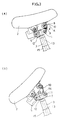
- Fig. 1 shows the in-service state of a bicycle with an antitheft device according to an embodiment of the invention, (a) through (d) showing the transition from the in-service state to the locked parked state, (e) and (f) showing the transition from the locked parked state to the in-service state.
- the in-service state is meant, as prescribed by Japanese Industrial Standard (JIS D9101), a state of a bicycle which allows a person to ride, or a state of a bicycle in which a person uses the bicycle as he rides it.
- JIS D9101 Japanese Industrial Standard
- the stand 1 In operative connection with the turning of the saddle 2, the stand 1 is locked by a stand locking device 4 as shown in (c) of Fig. 1.
- the key 6 is inserted, for unlocking, into the cylinder lock 5 which is a first locking means and the saddle 2 is restored as shown in (f) of Fig. 1, thereby unlocking the stand 1 which has been locked by the stand locking device 4 serving as a second locking means and a movable section.
- the stand 1 is leveled, whereby the state is changed into the in-service state.
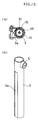
- the saddle 2 is attached to the upper end of the seat pillar 3 by a mounting member 7.
- the saddle 2 is attached to the mounting member 7 through the cylinder lock 5 so that it is turnable around the cylinder lock as shown in (b) of Fig. 3 and (a) and (b) of Fig. 4.
- the saddle 2 is provided with a lever 10 which is turnably supported on a pin 8 and urged in the direction of arrow A by a spring 9, it being arranged that in the in-service state, the front end of the lever 10 is engaged with the mounting screw shaft 11 of the mounting member 7 to prevent the turning of the saddle 2.
- the saddle 2 is provided with an integrally turnable sector gear 12, while the seat pillar 3 is internally provided with a liftably supported connecting rod 13 serving as connecting means.
- the upper end portion of the connecting rod 13 is formed with a toothed rack 14 with which the sector gear 12 operatively connected with the saddle 2 is meshing.
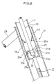
- the seat pillar 3 is fitted in the seat tube 15 of the bicycle frame as shown in Fig. 2, and the position of the seat pillar 3 relative to the seat tube 15 is controlled by tightening the handle 17 of a seat lug 16 at a position where the saddle level is suitable, so as to prevent movement of the seat pillar 3.
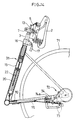
- the stand locking device 4 comprises a locking lever 19 pivotally supported at its intermediate portion on a shaft 18 in the vicinity of the base end of the stand 1, a cylinder 20 liftably received in the lower end portion of the seat tube 15, and a link 21 which connects the lower end of the cylinder 20 to the base end of the locking lever 19.
- Screwed into the upper end of the cylinder 20 is a threaded portion 22 formed on the lower end of the connecting rod 13, so that the cylinder 20 will be lifted and lowered inside the seat tube 15 in operative connection with the upward and downward movement of the connecting rod 13. Further, the center of the seat tube 15 and the center O of the crank are in a non-crossing state to prevent the link 21 from interfering with the crank.
- the connecting rod 13 has locking cams 23a and 23b attached to the intermediate portion thereof by pins 24, as shown in Figs. 2 and 6, which cams serve as fixing means and movable sections.
- the lower end of the seat pillar 3 is formed with openings 25a and 25b and bent elements 26a and 26b inwardly bent for insertion into the upper regions of said openings 25a and 25b.
- the numeral 29 denotes a seat stay and 30 denotes a chain stay.
- the connecting rod 13, as shown in Fig. 7, is formed with a recess 28, so that in the state in which the saddle 2 is restored to the in-service position by using the genuine key 6, the locking cams 23a and 23b, as shown in Fig. 6, are restored to their original positions with the rollers 27a and 27b partly received in the recess 28.
- the stand 1 can be locked in operative connection with the turning of the saddle 2 in the manner shown in (b) of Fig. 1, while at the time of unlocking, the stand 1 can be unlocked in operative connection with the turning of the saddle 2 in the manner shown in (f) of Fig. 1, thus improving the operability.
- the bicycle with an antitheft device in this embodiment is reliably protected from theft in that the following fixing means 31 is provided so that the stand 1 can be maintained in the locked state shown in Fig. 5.
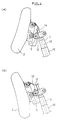
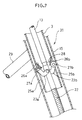
- the connecting rod 13 may be replaced by a wire structure as in a second embodiment shown in Figs. 8 and 9.
- the numeral 41 denotes an outer wire and 42 denotes an inner wire which, except for its opposite ends, is held by the outer wire 41 so that it can come in and out, the upper end of said inner wire 42 being attached to a saddle support block 43 which supports the saddle 2, the lower end of said inner wire 42 being connected to a swing lever 44 which is pivotally supported for swing movement in the stand locking device 4. And when the saddle 2 is turned upward so as to enter into the parked state as shown in Figs.
- the inner wire 42 is pulled up to swing the swing lever 44 of the stand locking device 4, whereby the locking lever 45 pivotally connected to said swing lever 44 through a pin 39 is lowered along a cam groove 38 through the intermediary of the pin 39 to extend along the rear surface of the base portion of the stand 1. Therefore, an attempt to turn the stand 1 rearward will result in the stand 1 abutting against the locking lever 45; thus, any attempt to level the stand 1 is defeated, the stand 1 being locked in the erected state.
- the numeral 46 denotes a support seat for the outer wire 41 fixed to the interior of the upper end portion of the seat pillar 3.
- the numeral 47 denotes a hook pivotally supported by a mounting member 48 fixed to the upper end of the seat pillar 3, said hook being engageable with an engaging pin 49 fixed on the front end of the saddle support block 43.
- a connecting pin 50 for connecting the mounting member 48 of the seat pillar 3 to the saddle support block 43 has an urging spring 51 fitted thereon to serve as elastic means, said urging spring 51 urging the saddle 2 toward the parked position.
- the saddle 2 is supported such that it can be manually moved from the parked position to the in-service position against the force of the urging spring 51. If, therefore with the saddle 2 in the in-service position, one end of the hook 47 is depressed to disengage the other end thereof from the engaging pin 49, the saddle 2 is pushed up by the force of the urging spring 51 and turned until it reaches the parked position.
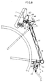
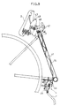
- a rod 61 and a wire structure may be used as means for establishing the operative connection between the turning movement of the saddle 2 and the stand locking device 4.
- the rod 61 is connected to the saddle 2 and the upper end of the inner wire 42 is connected to the lower end of the rod 61.
- the connecting wire the wire for connection
- a vertically extending elongated opening 62 is formed in the seat tube 15 supporting the seat pillar 3, and a locking bolt 63 serving as a seat pillar slip-off preventing member extends through said elongated opening 62 radially outwardly of the seat pillar 3 and is screwed into the seat pillar 3.
- This locking bolt 63 is removable only by using a special tool different from tools in general use, such as plus drivers, minus drivers and hexagon bar spanners.
- the head of the locking bolt 63 is formed with a right pentagonal hole, so that the locking bolt 63 can be turned only by a special pentagonal bar spanner.
- any attempt to extract the seat pillar 3 from the seat tube 15 is defeated in that the locking bolt 63 abuts against the upper end of the elongated opening 62 in the seat tube 15, preventing such extraction.
- the seat pillar 3 itself can be prevented from slipping off the seat tube 15, the saddle 2 is protected from being replaced by a saddle in general use.
- the seat pillar 3 is lifted or lowered to adjust the height of the saddle 2, and then the cylinder lock 5 is fastened and engaged in a portion thereof (not shown) with the toothed portion 61a of the rod 61, thereby fixing the height.
- the opening 62 in the seat tube 15 is elongated; however, the invention is not limited thereto and if height adjustment is unnecessary, a simple circular opening may be employed.
- the projecting height of the head of the locking bolt 63 serving as a seat pillar slip-off preventing member is not limited to the one shown in the above embodiment; it has only to function to prevent slip-off, and any height may be employed so long as it is larger than the diameter of the upper end opening in the seat tube 15.
- a seat pillar slip-off preventing member such as a bolt of general shape may be fixed in position by soldering or by using a an adhesive agent made of thermoplastic resin. According to this arrangement, since it cannot be removed except by a special method such as heating by high frequency waves, the same effects can be obtained.
- a fourth embodiment of the invention is shown in Fig. 12 and (a) and (b) of Fig. 13.
- a split spacer 65 partly cut in flat shape is fitted in the upper end of the seat tube 15, with the result that the inner shape of the seat tube 15 is non-circular. Further, in conformity therewith, the portion of the seat pillar 3 to be inserted in the seat tube 15 is laterally cut to provide a flat portion 3a.
- the inner shape of the seat tube 15 may be elliptic or any other shape so long as it is non-circular.
- a spacer 65 separate from the seat tube 15 is provided, and the inner shape of this spacer 65 is made non- circular; since this spacer 65 is processed separately from the seat tube 15 which is part of the frame, it can be produced with a high degree of precision, providing the effect that the force with which the saddle 2 is fixed can be increased.
- the invention is not limited thereto.
- Fig. 14 shows a fifth embodiment of the invention.
- a connecting wire 70 is connected to the lower end of a cylinder 20 of the same construction as that shown in Fig. 1.
- the front end of this connecting wire 70 is attached to a slide lever 73 slidably designed and transversely disposed in the vicinity of a hub brake device 72 for the rear wheel 71 which serves as second locking means and movable section.
- the slide lever 73 is forwardly moved along a groove 74a in a support guide 74 through the intermediary of the cylinder 20 and the connecting wire 70, as shown in solid line in Fig. 14, so as to actuate the brake device 72.
- the hub brake device 72 for the rear wheel 71 will be automatically actuated in operative connection with the turning movement of the saddle 2 to brake the bicycle in the non-running state.
- the numeral 75 in Fig. 14 denotes a wire connected to a brake lever (not shown), and the hub brake device 72 can be actuated also by the brake lever.
- the front end of a connecting wire 83a which transmits the turning movement of the saddle 2 from the in-service state to the parked state may be connected to a brake device 80 of the type which presses a brake shoe 81 against the rim 82 of the rear wheel 71. That is, when the saddle 2 is turned from the in-service state to the parked state, as shown in (a) and (b) of Fig.
- a cam 84 connected to the front end of the inner wire 83a is turned around the axis of a shaft 84a to spread a brake arm 85, whereby the brake shoe 81 attached to the brake am 85 abuts against the rim 82 of the rear wheel 71, thus braking the latter.
- 83b denotes an outer wire for the connecting wire 83 and 75 denotes a wire connected to a brake lever (not shown), it being arranged that, as shown in (c) of Fig. 16, the brake device 80 can be actuated also by the brake lever.
- return springs are provided for urging the cam 84 and brake arm 85 to the state shown in (a) of Fig. 16.
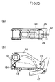
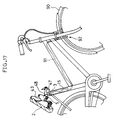
- Figs. 17 and 18 show a seventh embodiment of the invention, wherein a connecting wire 91 for transmitting the turning movement of the saddle 2 from the in-service state to the parked state is connected to a circle lock 92 provided for the front wheel 90. And when the saddle 2 is turned from the in-service position to the parked position, as shown in (a) and (b) of Fig. 18, the locking bar 93 of the circle lock 92 is inserted between spokes 94 of the front wheel 90 by the inner wire 91a to prevent the rotation of the front wheel 90.
- 91b denotes the outer wire of the connecting wire 91; 95 denotes a return spring for urging the locking bar 93 toward the unlocking side, and 96 denotes a wire attaching hole.
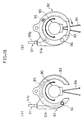
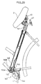
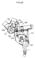
- Figs. 19 and 20 show en eighth embodiment of the invention, wherein a connecting wire 101 which transmits the turning movement of the saddle 2 from the in-service state to the parked state is connected to a handle locking mechanism 100 which makes the handle 102 immovable. And when the saddle 2 is turned from the in-service position to the parked position, as shown in (a) and (b) of Fig. 20, the cam 103 of the handle locking mechanism 100 is turned through the inner wire 101a of the connecting wire 101, and the locking pin 104 adapted to be forwardly projected by the cam 103 fits in one of the engaging holes 107a in a front fork stem 107 connected to a head tube 105.
- the saddle 2 is locked by the cylinder lock 5 in response to its turning movement to the parked state, and the handle 102 is automatically nonrotatably fixed by the handle locking mechanism 100 in operative connection with the turning movement of the saddle 2; thus, any attempt to ride will fail.
- the characters 103a and 104a denote return springs for the cam 103 and the locking pin 104.
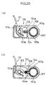
- a handle locking mechanism 110 of different construction may be used to restrain the handle 102 from moving. That is, an engaging member 111 having an arm 111a adapted to move into and out of engagement with an octagonal section 106a formed in the front fork 106 is connected to the front end of the inner wire 101a of the connecting wire 101 through a crank lever 112. Therefor, when the saddle 2 turned from the in-service position to the parked position, it is locked by the cylinder lock 5 and, as shown in (a) - (c) of Fig.
- the arm 111a of the engaging member 111 engages the octagonal section 106a of the front fork 106 through the crank lever 112 which is pulled by the inner wire 101a of the connecting wire 101, whereby the front fork 106, the handle stem 109 and handle 102 fixed to said front form 106 are restrained from moving.
- the handle 102 in operative connection with the turning movement of the saddle 2, the handle 102 is automatically nonrotatably fixed by the handle locking mechanism 110, so that any attempt to ride will fail.
- the character 111b denotes a return spring for the engaging member 111.
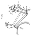
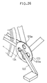
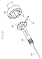
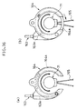
- Figs. 23 through 26 show a tenth embodiment of the invention, wherein the parts having the same constructions or functions as in the preceding embodiment are denoted by the same reference characters as used before and a detailed description thereof is omitted, and chiefly the parts different from those described above will be described.
- a connecting wire 121 which transmits the turning movement of the saddle 2 from the in-service state to the parked state is connected to a crank locking mechanism 120 which restrains a crank arm 122 from moving. And when the saddle 2 is turned from the in-service position to the parked position, as shown in Figs.
- a locking bar 124 connected to a crank lever 125 which is adapted to swing around the axis of a shaft 125a connected to the inner wire 121a of a connecting wire 121 is inserted into an ornamental hole 123a in a gear plate 123.
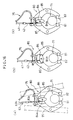
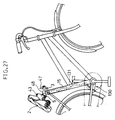
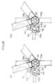
- Figs. 27 and 28 show an 11th embodiment of the invention, wherein the parts having the same constructions or functions as in the preceding embodiment are denoted by the same reference characters as used before and a detailed description thereof is omitted, and chiefly the parts different from those described above will be described.
- a connecting wire 131 which transmits the turning movement of the saddle 2 from the in-service state to the parked state is connected to a crank locking mechanism 130 which restrains the crank shaft 132 from moving. That is, in this embodiment, the crank shaft 132 is formed with a plurality of teeth 132a, and a support plate 134 installed in the vicinity of the crank shaft 132 is provided with a crank lever 136 which swings through a pin 135. Further, one end of a crank lever 136 is connected to the inner wire 131a of the connecting wire 131.
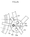
- Figs. 29 and 30 show a 12th embodiment of the invention, wherein the parts having the same constructions or functions as in the preceding embodiment are denoted by the same reference characters as used before and a detailed description thereof is omitted, and chiefly the parts different from those described above will be described.
- a connecting wire 141 which transmits the turning movement of the saddle 2 from the in-service state to the parked state may be connected to a crank stand locking mechanism 140 which restrains a pedal crank shaft 132 from moving and which locks the stand 1 in the erected state.
- the crank stand locking mechanism 140 which performs two functions, namely, the function of locking the stand 1 in the erected state and the function of restraining the turning movement of the pedal crank shaft 132, three functions of the bicycle are regulated, so that the bicycle is protected more positively from being stolen.
- no cylinder lock is illustrated; however, it goes without saying that such cylinder lock may be provided in the saddle 2 or the crank stand locking mechanism 140.
- Figs. 31 through 33 show a 13th embodiment of the invention, wherein the parts having the same constructions or functions as in the preceding embodiment are denoted by the same reference characters as used before and a detailed description thereof is omitted, and chiefly the parts different from those described above will be described.
- a connecting wire 151 which transmits the turning movement of the saddle 2 from the in-service state to the parked state is connected to a hub locking mechanism 150 which restrains the hub body 152 of the front wheel 90 from moving.
- an L-shaped crank swingable lever 153 is connected to the inner wire 151a of the connecting wire 151, and said L-shaped crank lever 153 is connected through a crank rod 154 to a slide member 155, which is movable transversely of a hub shaft 156 within the hub body 152, by a pin 157.
- the slide member 155 is substantially in the form of a gear, and the portion of the hub body 152 corresponding to the slide member 155 is also formed with internal toothed section 152a of similar shape.
- the numeral 158 denotes a bearing for rotatably supporting the hub body 152 with respect to the hub shaft 156
- 159 denotes a spring for urging the slide member 155 away from the internal toothed section 152a of the hub body 152.
- Figs. 34 through 36 show a 14th embodiment of the invention.
- the parts having the same constructions or functions as in the preceding embodiment are denoted by the same reference characters as used before and a detailed description thereof is omitted, and chiefly the parts different from those described above will be described.
- a connecting wire 163 which, separate from a wire 162 associated with the brake device for the front wheel 90, transmits an operation directed to the lock position (see (b) of Fig. 35) of a brake lever 161 for braking the front wheel 90 to said brake lever 161 is connected to a circle lock 164 installed on the rear wheel 71. And when the brake lever 161 is operated to move from the in-service position shown in (a) of Fig.
- the locking bar 164a of the circle lock 164 is inserted between spokes 165 of the rear wheel 71 by the inner wire 163a of the connecting wire 163, as shown in (a) and (b) of Fig. 36, thereby preventing the rear wheel 71 from rotating.
- the circle lock 164 for the rear wheel 71 is automatically locked in the non-running state in operative connection with the locking operation of the brake lever 161; thus, performing such locking operation makes it impossible to operate the brake lever 161 and inhibits the rotation of the rear wheel 71.
- the numeral 166 denotes a cylinder lock for locking the brake lever 161 in the locked position
- 167 denotes a protective bar for protecting the brake lever 161 from moving to the locked position during use.
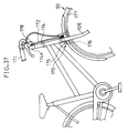
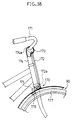
- Figs. 37 through 39 show a 15th embodiment of the invention.
- the parts having the same constructions or functions as in the preceding embodiment are denoted by the same reference characters as used before and a detailed description thereof is omitted, and chiefly the parts different from those described above will be described.
- the handle 171 is downwardly turnable, it being arranged that when the handle 171 is turned downward, a front wheel locking device 170 for braking the front wheel 90 is actuated through the connecting wire 172.
- a circular member 173 attached to the middle of the handle 171 is turnable around a transverse axis in a cylindrical frame 174a formed in the upper end of the handle stem 174, and the inner wire 172a of the connecting wire 172 is connected to said circular member 173.
- a connecting lever 175 swingably supported on a front fork 106, and a brake member 176 attached to said connecting lever 175 is allowed to abut against the tire 177 of the front wheel 90.
- the handle 171 which is automatically locked by the cylinder lock 178, is turned downward, it becomes hard to hold by hand and with this downward turning movement, the brake member 176 is pressed against the tire 177 of the front wheel 90 through the connecting wire 172 and connecting lever 175, thereby restraining the rotation of the front wheel 90.
- the numeral 178 in Fig. 37 denotes a cylinder lock for locking the handle 171 in its individual positions (the upper normal position and the lower abnormal position).
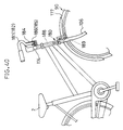
- Figs. 40 through 42 show a 16th embodiment of the invention.
- the parts having the same constructions or functions as in the preceding embodiment are denoted by the same reference characters as used before and a detailed description thereof is omitted, and chiefly the parts different from those described above will be described.
- handles 181 and 182 are turnable, it being arranged that when these handles 181 and 182 are turned downward, a front wheel locking device 180 for braking the front wheel 90 is actuated through a connecting piston member 188.
- a handle support plate 184 is attached forwardly of the handle stem 174, and handles 181 and 182 are turnable around the axes of shafts 185 and 186 attached to said handle support plate 184 (the shaft of the cylinder lock described in the preceding embodiment is utilized in order to lock the handles 181 and 182 in the in-service position and in the parked position).
- a handle connecting member 187 fixed to one handle 181 abuts against the upper plate 188a of the connecting piston member 188 liftably supported in a head tube 105, and a brake member 189 attached to the lower end of said connecting piston member 188 is adapted to abut against tire 177 of the front wheel 90.
- handles 181 and 182 which are locked by the cylinder lock, are unlocked by the key and turned downward to the parked position, they are rendered hard to hold by hand. And as the handle 181 is turned downward, the brake member 189 is pressed against the tire 177 of the front wheel 90 through the connecting piston member 188, thereby restraining the rotation of the front wheel 90.
- 188b in Figs. 40 through 42 denotes a spring for urging the connecting piston upward.
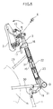
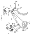
- Figs. 43 through 45 show a 17th embodiment of the present invention.
- the parts having the same constructions or functions as in the preceding embodiment are denoted by the same reference characters as used before and a detailed description thereof is omitted, and chiefly the parts different from those described above will be described.
- the movement of the saddle 2 is operatively connected with the movement of the stand 1. That is, connected to the upper end of the connecting rod 191 for transmitting their movements is a hook 195 which is pivotally supported by a mounting member 48 disposed on the upper end of the seat pillar 3, said hook 195 being engageable with an engaging pin 49 fixed on the front end of the saddle support block 43.
- the stand 1 is connected to the lower end of the connecting rod 191 through a first connecting link 192 and a second connecting link 193. And when the stand 1 is moved from the in-service position to the parked position, where the stand 1 is then erected, this movement of the stand 1 is transmitted to the hook 195 through the first connecting link 192, second connecting link 193 and connecting rod 191, whereupon the hook 195 is disengaged from the engaging pin 49 of the saddle support block 43, allowing the saddle 2 to be turned to the parked state.
- a cylinder lock 194 is provided in the vicinity of the saddle 2. It is arranged that a locking lever 194a adapted to project when the cylinder lock 194 is fastened presses the recess 195a in the hook 195 to turn the saddle 2 until the latter assumes the parked state while the stand 1 is brought from the in-service position to the parked position.
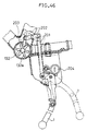
- Fig. 46 shows a 18th embodiment of the invention.
- the parts having the same constructions or functions as in the preceding embodiment are denoted by the same reference characters as used before and a detailed description thereof is omitted, and chiefly the parts different from those described above will be described.
- a locking toothed section 203 formed on the second connecting link 202 meshes with a toothed section 132a formed on a pedal crank shaft 132, thereby restraining the pedal crank 132 from moving.
- erecting the stand 1 makes it impossible to rotate the pedal crank shaft 132 and hence to ride the bicycle.
- 204 denotes a cylinder lock which, when the stand 1 is erected, automatically lock the stand 1 in that state.
- the locking operation of the saddle locking device 211 for locking the saddle in the parked state may be operatively connected with the brake locking device 212 for actuating the brakes, the stand locking device 213 for locking the stand in the erected state, and the wheel locking device 214 such as a circle lock for locking the wheel.
- the plurality of functional means different in function constituting the bicycle mention has been made of the saddle 2, running parts such as the front wheel 90 and rear wheel 71, and the torque transmission parts such as the handle 102 and pedal crank 122; however, the invention is not limited thereto.
Landscapes
- Engineering & Computer Science (AREA)
- Mechanical Engineering (AREA)
- Lock And Its Accessories (AREA)
- Steering Devices For Bicycles And Motorcycles (AREA)
- Axle Suspensions And Sidecars For Cycles (AREA)
Applications Claiming Priority (9)
| Application Number | Priority Date | Filing Date | Title |
|---|---|---|---|
| JP34027696 | 1996-12-20 | ||
| JP34027696 | 1996-12-20 | ||
| JP340276/96 | 1996-12-20 | ||
| JP9781697 | 1997-04-16 | ||
| JP97816/97 | 1997-04-16 | ||
| JP9781697 | 1997-04-16 | ||
| JP26910297 | 1997-10-02 | ||
| JP269102/97 | 1997-10-02 | ||
| JP26910297A JP3432397B2 (ja) | 1996-12-20 | 1997-10-02 | 盗難防止装置付き自転車 |
Publications (2)
| Publication Number | Publication Date |
|---|---|
| EP0849148A2 true EP0849148A2 (de) | 1998-06-24 |
| EP0849148A3 EP0849148A3 (de) | 2002-01-02 |
Family
ID=27308497
Family Applications (1)
| Application Number | Title | Priority Date | Filing Date |
|---|---|---|---|
| EP19970121971 Withdrawn EP0849148A3 (de) | 1996-12-20 | 1997-12-12 | Anti- Diebstahlvorrichtung für Fahrrad |
Country Status (5)
| Country | Link |
|---|---|
| US (1) | US6036214A (de) |
| EP (1) | EP0849148A3 (de) |
| JP (1) | JP3432397B2 (de) |
| CN (1) | CN1090113C (de) |
| TW (1) | TW450907B (de) |
Cited By (8)
| Publication number | Priority date | Publication date | Assignee | Title |
|---|---|---|---|---|
| US6036214A (en) * | 1996-12-20 | 2000-03-14 | Matsushita Electric Industrial Co., Ltd. | Bicycle with antitheft device |
| WO2000003913A3 (en) * | 1998-07-16 | 2001-12-20 | Andries Gaastra | Cycle, in particular a bicycle |
| EP1388489A1 (de) * | 2002-08-07 | 2004-02-11 | Biria AG | Abschliessbare Zweiradstütze |
| KR100492087B1 (ko) * | 1996-12-20 | 2005-11-11 | 마쯔시다덴기산교 가부시키가이샤 | 도난방지장치가부착된자전거 |
| WO2008119349A1 (en) * | 2007-03-29 | 2008-10-09 | Madsen, Kurt | A bicycle with anti-theft protection. |
| WO2008155754A1 (en) * | 2007-06-17 | 2008-12-24 | Ino Logic Ltd. | Bicycle apparatus usable as a seat support device and as a bicycle lock |
| WO2009146549A1 (en) * | 2008-06-06 | 2009-12-10 | Société de vélo en libre-service | Seat anti-theft assembly and method of installing the same |
| WO2012089941A1 (fr) * | 2010-12-31 | 2012-07-05 | Decathlon | Dispositif de blocage entre deux tubes montes a coulissement |
Families Citing this family (23)
| Publication number | Priority date | Publication date | Assignee | Title |
|---|---|---|---|---|
| JP2001132300A (ja) * | 1999-08-20 | 2001-05-15 | Miyata Ind Co Ltd | 自転車の施錠装置 |
| JP4556053B2 (ja) * | 2001-02-27 | 2010-10-06 | 株式会社ニッコー | 自転車錠 |
| KR100727971B1 (ko) | 2005-09-01 | 2007-06-14 | 삼성전자주식회사 | 와이퍼, 클리닝 장치, 및 이를 구비하는 잉크젯화상형성장치 |
| CN101209731B (zh) * | 2006-12-31 | 2012-02-22 | 胡立群 | 自行车 |
| CN102066188A (zh) * | 2008-05-09 | 2011-05-18 | 科兰克罗科有限公司 | 自行车曲柄锁具 |
| CN102226363B (zh) * | 2011-05-25 | 2013-01-09 | 无锡万紫共用车系统有限公司 | 一种自行车车锁系统 |
| WO2015193785A1 (en) * | 2014-06-16 | 2015-12-23 | Ino Vision Ltd. | Bicycle seat and lock assembly |
| ES2709373T3 (es) * | 2014-09-12 | 2019-04-16 | Technogym Spa | Máquina de gimnasia con grupo de ajuste |
| HUP1400455A2 (hu) * | 2014-09-26 | 2016-03-29 | Csaba Hollo | Hajlékony lakatszerkezet kerékpárok ellopás elleni védelmére |
| US10207758B2 (en) | 2017-06-23 | 2019-02-19 | GM Global Technology Operations LLC | Kickstand assembly and a bicycle that utilizes the kickstand assembly |
| CN107323577B (zh) * | 2017-06-27 | 2023-10-27 | 鲁安予 | 与鞍管一体的折叠鞍座及其折叠展开方法 |
| CN107933749B (zh) * | 2017-11-22 | 2020-01-17 | 张长江 | 一种手把式骑行车的插把式车锁 |
| CN109649539B (zh) * | 2018-12-14 | 2024-02-09 | 重庆宗申创新技术研究院有限公司 | 一种电子座垫锁的结构 |
| CN109533120B (zh) * | 2018-12-25 | 2020-08-21 | 江西玉祥智能装备制造有限公司 | 一种用于单车的自触发式避热坐垫 |
| WO2020233535A1 (zh) * | 2019-05-17 | 2020-11-26 | 北京嘀嘀无限科技发展有限公司 | 一种车锁控制装置、方法及车辆 |
| DE102019213136A1 (de) * | 2019-08-30 | 2021-03-04 | Ulrich Preß | Sattelstütze, Faltschloss und Absperrsystem |
| JP6784427B1 (ja) * | 2019-12-20 | 2020-11-11 | 株式会社トラストコーポレーション | 二輪車の補助輪機構 |
| JP7231577B2 (ja) * | 2020-03-12 | 2023-03-01 | 本田技研工業株式会社 | 自転車 |
| DE102022116748A1 (de) * | 2022-07-05 | 2024-01-11 | Salem Katary | Sicherheitssystem für ein Fahrrad mit einer Tretkurbel-Sicherungsvorrichtung |
| DE102022213201A1 (de) * | 2022-12-07 | 2024-06-13 | Ulrich Preß | Sattelstütze |
| US12441422B2 (en) | 2023-03-21 | 2025-10-14 | Honda Motor Co., Ltd. | Foldable seat with latching mechanism for personal transport device |
| CN116834879A (zh) * | 2023-06-09 | 2023-10-03 | 广东球德健康科技有限公司 | 一种方便调节的电动助力自行车 |
| CN117087794A (zh) * | 2023-08-15 | 2023-11-21 | 北京阿帕科蓝科技有限公司 | 用于助力车的脚撑机构及助力车 |
Family Cites Families (28)
| Publication number | Priority date | Publication date | Assignee | Title |
|---|---|---|---|---|
| DE101055C (de) * | ||||
| DE246232C (de) * | ||||
| DE105092C (de) * | ||||
| FR869214A (fr) * | 1941-01-14 | 1942-01-27 | Tige de selle antivol pour bicyclette | |
| JPS5628075Y2 (de) * | 1976-05-07 | 1981-07-03 | ||
| NL8100343A (nl) * | 1981-01-26 | 1982-08-16 | Robert Johannes Wilcke | Fietsslot. |
| IT1061204B (it) * | 1981-10-15 | 1983-01-27 | Silla M | Dispositivo anti-furto per motociclie applicato al cavalletto di stazionamento |
| JPS5875092A (ja) * | 1981-10-30 | 1983-05-06 | 株式会社東芝 | 沸騰水形原子炉 |
| DE3211367A1 (de) | 1982-03-27 | 1983-10-06 | Egon Gelhard | Zweirad, insbesondere fahrrad mit einem staender |
| US4571965A (en) * | 1983-08-31 | 1986-02-25 | Leroux Paul | Bicycle lock |
| NL8400707A (nl) * | 1984-03-05 | 1985-10-01 | Drs Johannes Carel Van Wierst | Grendelinrichting voor een rijwiel. |
| US4841757A (en) | 1988-06-07 | 1989-06-27 | Guthrie Richard A | Bicycle lock |
| CN2058896U (zh) * | 1989-07-09 | 1990-07-04 | 王政光 | 自行车支架车锁机构 |
| DE9015395U1 (de) * | 1990-11-09 | 1991-01-24 | Kirschner, Michael, 8751 Stockstadt | Fahrrad mit Diebstahlsicherung |
| US5114167A (en) * | 1991-01-08 | 1992-05-19 | Shieh Jin Ren | Locking apparatus for use in a motor cycle stand |
| JPH05246359A (ja) * | 1991-03-18 | 1993-09-24 | Honda Motor Co Ltd | 自動二輪車のメインスタンド |
| CN2126843Y (zh) * | 1992-07-06 | 1993-02-10 | 朱伟 | 封闭连体式自行车防盗保险装置 |
| CN2165063Y (zh) * | 1993-04-10 | 1994-05-18 | 李清 | 自动锁车支架 |
| DE4320663C2 (de) * | 1993-06-22 | 1996-10-02 | Vetterick Hans Juergen | Sicherungseinrichtung für Fahrräder |
| US5433552A (en) * | 1994-02-28 | 1995-07-18 | Thyu; Chorng-Thyong | Seat pillar lock device for exercising machines |
| JP3496988B2 (ja) * | 1994-10-05 | 2004-02-16 | ナショナル自転車工業株式会社 | 自転車 |
| US5553880A (en) * | 1994-12-06 | 1996-09-10 | Mcjunkin; Mark P. | Energy-absorber for a bicycle frame |
| JP3652730B2 (ja) * | 1995-03-03 | 2005-05-25 | ヤマハ発動機株式会社 | 自転車シートの回動装置 |
| JPH08310463A (ja) * | 1995-05-17 | 1996-11-26 | Kanto Auto Works Ltd | 折り畳み自転車用サドルのロック機構 |
| US5618052A (en) * | 1995-06-15 | 1997-04-08 | Rendall; Barry A. | Bicycle attachment |
| US5678435A (en) * | 1995-08-14 | 1997-10-21 | Hodson; James M. | Bicycle locking mechanism |
| JP3432397B2 (ja) * | 1996-12-20 | 2003-08-04 | 松下電器産業株式会社 | 盗難防止装置付き自転車 |
| JPH11105756A (ja) * | 1997-10-02 | 1999-04-20 | Matsushita Electric Ind Co Ltd | 盗難防止装置付き自転車 |
-
1997
- 1997-10-02 JP JP26910297A patent/JP3432397B2/ja not_active Expired - Fee Related
- 1997-12-09 US US08/987,248 patent/US6036214A/en not_active Expired - Fee Related
- 1997-12-12 EP EP19970121971 patent/EP0849148A3/de not_active Withdrawn
- 1997-12-17 CN CN97108757A patent/CN1090113C/zh not_active Expired - Fee Related
- 1997-12-18 TW TW086119164A patent/TW450907B/zh active
Non-Patent Citations (1)
| Title |
|---|
| None |
Cited By (14)
| Publication number | Priority date | Publication date | Assignee | Title |
|---|---|---|---|---|
| KR100492087B1 (ko) * | 1996-12-20 | 2005-11-11 | 마쯔시다덴기산교 가부시키가이샤 | 도난방지장치가부착된자전거 |
| US6036214A (en) * | 1996-12-20 | 2000-03-14 | Matsushita Electric Industrial Co., Ltd. | Bicycle with antitheft device |
| WO2000003913A3 (en) * | 1998-07-16 | 2001-12-20 | Andries Gaastra | Cycle, in particular a bicycle |
| EP1388489A1 (de) * | 2002-08-07 | 2004-02-11 | Biria AG | Abschliessbare Zweiradstütze |
| WO2008119349A1 (en) * | 2007-03-29 | 2008-10-09 | Madsen, Kurt | A bicycle with anti-theft protection. |
| US8534754B2 (en) | 2007-06-17 | 2013-09-17 | Ino Vision Ltd. | Bicycle apparatus usable as a seat support device and as a bicycle lock |
| WO2008155754A1 (en) * | 2007-06-17 | 2008-12-24 | Ino Logic Ltd. | Bicycle apparatus usable as a seat support device and as a bicycle lock |
| WO2009146549A1 (en) * | 2008-06-06 | 2009-12-10 | Société de vélo en libre-service | Seat anti-theft assembly and method of installing the same |
| US8448971B2 (en) | 2008-06-06 | 2013-05-28 | Societe De Velo En Libre-Service | Seat anti-theft assembly and method of installing the same |
| FR2969981A1 (fr) * | 2010-12-31 | 2012-07-06 | Decathlon Sa | Dispositif de blocage entre deux tubes montes a coulissement |
| WO2012089941A1 (fr) * | 2010-12-31 | 2012-07-05 | Decathlon | Dispositif de blocage entre deux tubes montes a coulissement |
| CN103392073A (zh) * | 2010-12-31 | 2013-11-13 | 戴卡特隆有限公司 | 将两个可滑动安装的管相互锁定的装置 |
| US9010791B2 (en) | 2010-12-31 | 2015-04-21 | Decathlon | Locking device for locking together two slidably mounted tubes |
| CN103392073B (zh) * | 2010-12-31 | 2015-05-27 | 戴卡特隆有限公司 | 将两个可滑动安装的管相互锁定的装置 |
Also Published As
| Publication number | Publication date |
|---|---|
| JPH111189A (ja) | 1999-01-06 |
| CN1185392A (zh) | 1998-06-24 |
| TW450907B (en) | 2001-08-21 |
| CN1090113C (zh) | 2002-09-04 |
| US6036214A (en) | 2000-03-14 |
| JP3432397B2 (ja) | 2003-08-04 |
| EP0849148A3 (de) | 2002-01-02 |
Similar Documents
| Publication | Publication Date | Title |
|---|---|---|
| US6036214A (en) | Bicycle with antitheft device | |
| WO1993014956A1 (en) | Control lever lock | |
| EP0774405B1 (de) | Verriegelungsvorrichtung für eine Lenkstange | |
| JPH05507668A (ja) | 自転車用の簡易締付けボス | |
| KR100492087B1 (ko) | 도난방지장치가부착된자전거 | |
| JP3470262B2 (ja) | 自転車用ハンドルロック装置 | |
| JP4248340B2 (ja) | 二輪車 | |
| EP0808268B1 (de) | Diebstahlsicherungssystem für fahrrad | |
| CN1072141C (zh) | 二轮、三轮摩托车的支架装置 | |
| US20190084633A1 (en) | Bicycle brake lock device and bicycle brake assembly comprising same | |
| JP3496988B2 (ja) | 自転車 | |
| JPH11105756A (ja) | 盗難防止装置付き自転車 | |
| AU782967B2 (en) | Vehicle anti-theft device | |
| JP2515270Y2 (ja) | 自転車のハンドルロック装置 | |
| JP2001097262A (ja) | コンビネイションロック装置 | |
| JP2001163282A (ja) | 省スペース型自転車用ハンドル | |
| JP3032825U (ja) | 自転車用ハンドル | |
| CN2219944Y (zh) | 双保险山地自行车锁 | |
| JPH11301543A (ja) | 盗難防止装置付き自転車 | |
| JP2000085650A (ja) | 自転車用スタンド、および自転車 | |
| CN2264123Y (zh) | 自行车防盗机构 | |
| CN2366518Y (zh) | 安全防盗自行车锁 | |
| JP3274462B1 (ja) | 車両用盗難防止装置 | |
| CN2184619Y (zh) | 防盗自行车 | |
| JP2006199113A (ja) | ロック機構 |
Legal Events
| Date | Code | Title | Description |
|---|---|---|---|
| PUAI | Public reference made under article 153(3) epc to a published international application that has entered the european phase |
Free format text: ORIGINAL CODE: 0009012 |
|
| AK | Designated contracting states |
Kind code of ref document: A2 Designated state(s): AT BE CH DE DK ES FI FR GB GR IE IT LI LU MC NL PT SE Kind code of ref document: A2 Designated state(s): CH DE FR GB IT LI NL |
|
| AX | Request for extension of the european patent |
Free format text: AL;LT;LV;MK;RO;SI |
|
| PUAL | Search report despatched |
Free format text: ORIGINAL CODE: 0009013 |
|
| AK | Designated contracting states |
Kind code of ref document: A3 Designated state(s): AT BE CH DE DK ES FI FR GB GR IE IT LI LU MC NL PT SE |
|
| AX | Request for extension of the european patent |
Free format text: AL;LT;LV;MK;RO;SI |
|
| RIC1 | Information provided on ipc code assigned before grant |
Free format text: 7B 62H 5/00 A, 7B 62H 5/06 B, 7B 62H 5/08 B |
|
| 17P | Request for examination filed |
Effective date: 20020513 |
|
| AKX | Designation fees paid |
Free format text: CH DE FR GB IT LI NL |
|
| RAP1 | Party data changed (applicant data changed or rights of an application transferred) |
Owner name: PANASONIC CORPORATION |
|
| STAA | Information on the status of an ep patent application or granted ep patent |
Free format text: STATUS: THE APPLICATION IS DEEMED TO BE WITHDRAWN |
|
| 18D | Application deemed to be withdrawn |
Effective date: 20100928 |