EP0849202B1 - Procédé et dispositif pour enrouler une bande de papier ou de carton - Google Patents
Procédé et dispositif pour enrouler une bande de papier ou de carton Download PDFInfo
- Publication number
- EP0849202B1 EP0849202B1 EP19970122029 EP97122029A EP0849202B1 EP 0849202 B1 EP0849202 B1 EP 0849202B1 EP 19970122029 EP19970122029 EP 19970122029 EP 97122029 A EP97122029 A EP 97122029A EP 0849202 B1 EP0849202 B1 EP 0849202B1
- Authority
- EP
- European Patent Office
- Prior art keywords
- reel
- drum
- pressure cylinder
- roll
- horizontal
- Prior art date
- Legal status (The legal status is an assumption and is not a legal conclusion. Google has not performed a legal analysis and makes no representation as to the accuracy of the status listed.)
- Expired - Lifetime
Links
Images


Classifications
-
- B—PERFORMING OPERATIONS; TRANSPORTING
- B65—CONVEYING; PACKING; STORING; HANDLING THIN OR FILAMENTARY MATERIAL
- B65H—HANDLING THIN OR FILAMENTARY MATERIAL, e.g. SHEETS, WEBS, CABLES
- B65H19/00—Changing the web roll
- B65H19/22—Changing the web roll in winding mechanisms or in connection with winding operations
- B65H19/2238—The web roll being driven by a winding mechanism of the nip or tangential drive type
- B65H19/2253—The web roll being driven by a winding mechanism of the nip or tangential drive type and the roll being displaced during the winding operation
- B65H19/2261—Pope-roller
-
- B—PERFORMING OPERATIONS; TRANSPORTING
- B65—CONVEYING; PACKING; STORING; HANDLING THIN OR FILAMENTARY MATERIAL
- B65H—HANDLING THIN OR FILAMENTARY MATERIAL, e.g. SHEETS, WEBS, CABLES
- B65H2301/00—Handling processes for sheets or webs
- B65H2301/40—Type of handling process
- B65H2301/41—Winding, unwinding
- B65H2301/417—Handling or changing web rolls
- B65H2301/418—Changing web roll
- B65H2301/4181—Core or mandrel supply
- B65H2301/41816—Core or mandrel supply by core magazine within winding machine, i.e. horizontal or inclined ramp holding cores
-
- B—PERFORMING OPERATIONS; TRANSPORTING
- B65—CONVEYING; PACKING; STORING; HANDLING THIN OR FILAMENTARY MATERIAL
- B65H—HANDLING THIN OR FILAMENTARY MATERIAL, e.g. SHEETS, WEBS, CABLES
- B65H2408/00—Specific machines
- B65H2408/20—Specific machines for handling web(s)
- B65H2408/23—Winding machines
- B65H2408/236—Pope-winders with first winding on an arc of circle and secondary winding along rails
Definitions
- the invention relates to a method and an apparatus for winding a paper or Cardboard web, the web on a roller, in particular drum, is wound up, the web being guided over a carrying drum and one empty roller, especially drum, in contact with the carrying drum is brought, the movement of the empty roller, in particular Drum, during the change of position from a storage position to Winding position takes place via swivel joints around the axis of the carrying drum and brought an empty roller into a storage position above the carrying drum becomes.
- Such devices are e.g. known from EP 330 169. Problematic in these devices is that the empty roller, in particular Tambour, with its full weight on the wrapped paper presses what especially with tissue paper crumplings and thus loss of quality brings itself. Furthermore, there is always a risk with these systems that the swiveling movement from the storage position into the operating (winding) position Position the empty roller can slide out of the holder and corresponding Causes damage.
- Other such devices are from known from EP 0 350 212, which a winding device of a paper or Cardboard web shows. The swivel lever has one at the end Support plate. This is done so that it is in the lower Position can tip down due to its own weight.
- a Similar device is also known from WO 94/18104.
- DE 44 01 804 also shows a winding device in which the empty roller by means of a lever taken from a magazine and into a carriage between the full roller and the drum. Only the paper web still running on the full roller is separated and turned the empty roller wound up. The beginning of the paper web is then by means of a Air jet blown so that it can be wound up by the empty roller can.
- the aim of the invention is to provide a method and an apparatus for of all movements during the change of position of the roller, in particular Reel, are as simple and safe as possible.
- the invention is concerned a process whereby an angle lever (10) is provided which is connected in an articulated manner to a swivel arm (12) and on which a pressure cylinder (8) for closing or opening a Holding device (6, 7) is provided and the holding of the axes of the empty Roller, especially drum, during the change of position Clamping by means of a pressure cylinder in a holding device, the is attached to the swivel arm rotatable about the axis of the support drum, and the weight of the empty Roller in the storage position by one connected to the swivel arm Pressure cylinder compensated and when changing the roller the empty roller, especially drum, lowered around a pivot point and at the same time the Weight compensation is reduced.
- This can be a simple Control of the roll change can be achieved with the Soiling a safe change takes place.
- An advantageous development is characterized in that the Weight compensation is reduced such that the contact line force is set according to a predetermined function.
- a favorable development of the invention is characterized in that the contact line force is constant during the entire swivel process is held.
- An advantageous development of the invention is characterized in that that after complete elimination of the weight components on the carrier drum a pulling force on the empty roller through the same pressure cylinder, especially drum, is exerted, with which the desired contact line force is set.
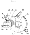
- An advantageous embodiment of the invention is characterized in that that the holding claws open in the horizontal position of the empty drum and the swivel arm is swiveled back into the receiving position, whereupon the next drum is removed and the new empty drum in whose position is managed. It is also faster and if necessary early reel change even with small reel diameters possible.
- a favorable embodiment of the invention is characterized in that the holding device for the empty roller, in particular drum, locked becomes. This is how it is opened accidentally during the swiveling process prevented.
- the invention also relates to a device for winding a paper or cardboard web, the web on a roller, in particular drum, is wound up, the web being guided over a carrying drum and one empty roller, especially drum, in contact with the carrying drum is brought, wherein a swivel arm is provided which about the axis of the Carrier drum is rotatable. It is characterized in that a Angle lever is provided, which is pivotally connected to the swivel arm is and on which a pressure cylinder for closing or opening one attached to the swivel arm Holding device is provided, with another on the swivel arm Pressure cylinder for weight compensation and pressing the empty roller, especially drum, is provided on the support drum.
- a favorable development of the invention is characterized in that at least one pressure cylinder is a hydraulic cylinder or alternatively one Pneumatic cylinder is.
- An advantageous embodiment of the invention is characterized in that that the further pressure cylinder is designed as a pressure and pull cylinder.
- Another advantageous embodiment of the invention is characterized in that that the holding device is pivotable about a pivot point Pawl and has a claw that can be pressed by a pressure cylinder.
- An advantageous development of the invention is characterized in that that the pawl and the claw snap into one another in the holding position, that they are with each other during the entire swiveling process are mechanically locked.
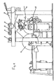
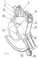
- Fig. 2 shows the detail of the support drum
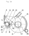
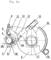
- Fig. 3 a to 3 f the sequence at Roller change
- Fig. 4 is an isometric view of a Show rewinder according to the invention.
- Fig. 1 shows a winding system in which the paper or cardboard web 1 over a support roller 2 passed and from there wound on a roller (drum) 3 becomes.
- the empty reels 4 are provided and via a Lever 5 fed to a holding device.
- Fig. 2 now represents the support roller 2 with the swivel device for the empty Drum 4 represents.
- a cylinder 8 By pressing a cylinder 8 is in the holding device inserted drum 4 clamped by a claw 6 in such a way that the claw engages in a pawl 7 and locks mechanically becomes. This is how the drum 4 becomes during the entire swiveling process always held positively; falling out of the claw 6 will thereby impossible.
- the claw 6 is via a pivot joint 9 with an angle lever 10 connected.
- This angle lever 10 is in turn via a swivel joint 11 connected to the swivel arm 12.
- the drum 4 recorded in the claw 6 by a Printing cylinder 13, which is connected to the angle lever 10 via a swivel joint 14 is compensated, i.e. the cylinder 13 exerts a counterforce to the Supporting roller acting weight component of the drum 4.
- the Swivel arm 12 is provided with a sprocket Segment 15 and a gear 16 about the axis 17 of the support drum 2nd pivoted.
- Fig. 3a shows the insertion of the reel 4 in the claw 6. It can be seen that the drum 4 lies loosely in the claw 6.
- Fig. 3 b represents the closing of the Claw 6 represents.
- the cylinder 8 presses the claw 6 against the drum 4, wherein the entire rocker arm 10 is pivoted about the pivot 11 and the claw 6 rotated about the hinge 9 and in positive Is brought into contact with the drum 4. Snaps during this movement the pawl 7 in the claw 6, so that a mechanical locking of the Claw 6 takes place and an opening during the pivoting process neither can be done intentionally or unintentionally.
- the drum 4 is brought into the winding position.
- the Swivel arm 12 by means of ring gear 15 through the gear 16 around the Axis 17 of the support drum 2 rotated. Put on the drum 4 on the support drum 2 is predetermined by the cam 20.
- This Function could also be controlled by appropriate control of the cylinder 13 respectively.
- the pressure of the cylinder 13 becomes Compensation of the weight component of the drum 4 on the Carrier drum 2 slowly reduced until the weight component of the corresponds to the desired contact pressure.
- the reduction of the compensation force can be done according to a given function. Usually it should be like this can be set that the contact line force of the drum 4 during the entire pivoting process remains constant.
- FIG. 4 now shows an isometric illustration of a winding system according to FIG Fig. 2, wherein the same parts with the corresponding reference numerals are.
- the invention is not limited by the examples, e.g. the Swiveling movement not necessarily over a tooth segment and a gear to be controlled.
Landscapes
- Replacement Of Web Rolls (AREA)
Claims (12)
- Procédé pour enrouler des nappes de papier ou de carton, dans lequel la nappe (1) est enroulée sur un rouleau (3), surtout un tambour d'enrouleuse, où la nappe (1) est menée sur un rouleau porteur (2) et où un rouleau vide (4), surtout un tambour d'enrouleuse, est mis en contact avec le rouleau porteur (2), où le mouvement du rouleau vide (4), surtout d'un tambour d'enrouleuse, s'effectue autour de l'axe (17) du rouleau porteur (2) via des charnières (9, 11) lors du changement de position, de la position de stockage à celle d'enroulement, et un rouleau vide (4) est mis à la position de stockage au-dessus du rouleau porteur (2), caractérisé en ce qu'un levier coudé 90° (10) est prévu qui est articulé à un bras pivotant (12) et pourvu d'un vérin de pression (8) servant à la fermeture et ouverture d'un dispositif d'arrêt (6, 7), et aussi caractérisé en ce que les arbres du rouleau vide (4), surtout d'un tambour d'enrouleuse, sont arrêtés lors du changement de position par le serrage par un vérin de pression (8) dans un dispositif d'arrêt (6, 7), le dispositif d'arrêt étant fixé au bras pivotant (12) qui peut tourner autour de l'axe du rouleau porteur (2), le poids du rouleau vide (4) en position de stockage se trouvant compensé par un autre vérin de pression (13) connecté au bras pivotant (12) et le rouleau vide (4), surtout un tambour d'enrouleuse, étant baissé autour d'un pivot lors du changement de rouleau, et la compensation du poids étant réduite en même temps.
- Procédé selon la revendication 1, caractérisé en ce que la compensation de poids est réduite de telle façon que la force de pression linéaire est réglée conformément à une fonction donnée.
- Procédé selon la revendication 2, caractérisé en ce que la force de pression linéaire est maintenue constante pendant le procédé de pivotage entier.
- Procédé selon l'une des revendications 1 à 3, caractérisé en ce que, après élimination complète de la compensation du poids, un effort de traction est appliqué au rouleau vide (4), par le vérin de pression (13) connecté au bras pivotant (12), à la suite de quoi ce rouleau est pressé au rouleau porteur (2).
- Procédé selon l'une des revendications 1 à 4, caractérisé en ce que, le rouleau vide (4) étant en position horizontale, le dispositif d'arrêt (6, 7) est ouvert et le bras pivotant (12) est retourné à la position de réception, à la suite de quoi le tambour d'enrouleuse plein est éjecté et le tambour d'enrouleuse vide est amené à sa place.
- Procédé selon l'une des revendications 1 à 5, caractérisé en ce que le dispositif d'arrêt pour le rouleau vide, surtout un tambour d'enrouleuse, est verrouillé.
- Dispositif pour enrouler des nappes de papier ou de carton, dans lequel la nappe (1) est enroulée sur un rouleau (3), surtout un tambour d'enrouleuse, où la nappe (1) est menée sur un rouleau porteur (2) et où un rouleau vide (4), surtout un tambour d'enrouleuse, est mis en contact avec le rouleau porteur (2), un bras pivotant (12) étant prévu qui peut tourner autour de l'axe du rouleau porteur (2), caractérisé en ce qu'un levier coudé 90° (10) est prévu qui est articulé au bras pivotant (12) et pourvu d'un vérin de pression (8) servant à la fermeture et ouverture d'un dispositif d'arrêt (6, 7) fixé au bras pivotant (12), où un autre vérin de pression (13) est prévu au bras pivotant (12) pour compenser le poids et pour presser le rouleau vide (4), surtout un tambour d'enrouleuse, contre le rouleau porteur.
- Dispositif selon la revendication 7, caractérisé en ce qu'au moins un vérin (8, 13) est un vérin hydraulique.
- Dispositif selon la revendication 7 ou 8, caractérisé en ce qu'au moins un vérin (8, 13) est un vérin pneumatique.
- Dispositif selon l'une des revendications 7 à 9, caractérisé en ce que l'autre vérin (13) est étudié en tant que vérin de pression et de traction.
- Dispositif selon l'une des revendications 7 à 10, caractérisé en ce que le dispositif d'arrêt a un loquet (7) qui peut tourner autour d'un pivot (9) et une griffe (6) pouvant être chargée par un vérin de pression (8).
- Dispositif selon la revendication 11, caractérisé en ce que, en position d'arrêt, le loquet (7) et la griffe (6) s'embrayent de façon à être verrouillés mécaniquement et réciproquement pendant le procédé de pivotage entier.
Applications Claiming Priority (3)
| Application Number | Priority Date | Filing Date | Title |
|---|---|---|---|
| AT2206/96 | 1996-12-18 | ||
| AT220696 | 1996-12-18 | ||
| AT220696A AT404824B (de) | 1996-12-18 | 1996-12-18 | Verfahren und vorrichtung zum aufwickeln einer papier- oder kartonbahn |
Publications (2)
| Publication Number | Publication Date |
|---|---|
| EP0849202A1 EP0849202A1 (fr) | 1998-06-24 |
| EP0849202B1 true EP0849202B1 (fr) | 2002-03-20 |
Family
ID=3529982
Family Applications (1)
| Application Number | Title | Priority Date | Filing Date |
|---|---|---|---|
| EP19970122029 Expired - Lifetime EP0849202B1 (fr) | 1996-12-18 | 1997-12-15 | Procédé et dispositif pour enrouler une bande de papier ou de carton |
Country Status (3)
| Country | Link |
|---|---|
| EP (1) | EP0849202B1 (fr) |
| AT (1) | AT404824B (fr) |
| DE (1) | DE59706672D1 (fr) |
Cited By (1)
| Publication number | Priority date | Publication date | Assignee | Title |
|---|---|---|---|---|
| CN108946252A (zh) * | 2017-05-24 | 2018-12-07 | 特吕茨施勒有限及两合公司 | 纤维网卷绕机的闭锁机构 |
Families Citing this family (10)
| Publication number | Priority date | Publication date | Assignee | Title |
|---|---|---|---|---|
| SE511829C2 (sv) * | 1998-03-16 | 1999-12-06 | Valmet Karlstad Ab | Rullstol i en pappersmaskin |
| DE10139340A1 (de) * | 2001-08-10 | 2003-02-27 | Voith Paper Patent Gmbh | Aufwickelvorrichtung |
| DE20117248U1 (de) * | 2001-10-24 | 2003-03-06 | Reinhold, Klaus, 49525 Lengerich | Vorrichtung zum Aufwickeln von Materialbahnen |
| ITFI20060201A1 (it) * | 2006-08-07 | 2008-02-08 | Focus S R L | Arrotolatore con dispositivo di protezione |
| CN105752729B (zh) * | 2016-04-29 | 2017-03-08 | 潍坊精诺机械有限公司 | 卷纸复卷机卷纸抽轴、换轴、落轴装置 |
| IT201900000241A1 (it) | 2019-01-09 | 2020-07-09 | Toscotec S P A | Macchina per l'avvolgimento di materiali nastriformi. |
| CN110027929B (zh) * | 2019-04-20 | 2020-09-08 | 青岛惠盟塑料有限公司 | 吹膜机的收卷装置 |
| CN110054005A (zh) * | 2019-05-22 | 2019-07-26 | 芜湖金三氏数控科技有限公司 | 一种自动换辊装置及其使用方法 |
| CN112209137A (zh) * | 2020-10-16 | 2021-01-12 | 吴江万工机电设备有限公司 | 一种无纺布卷绕机自动换筒装置 |
| CN113562511A (zh) * | 2021-08-25 | 2021-10-29 | 商立松 | 一种塑料薄膜自动换卷机 |
Family Cites Families (8)
| Publication number | Priority date | Publication date | Assignee | Title |
|---|---|---|---|---|
| US3614011A (en) * | 1969-12-22 | 1971-10-19 | Beloit Corp | Nip relieving apparatus for a reel |
| DE3015547C2 (de) * | 1980-04-23 | 1986-12-11 | J.M. Voith Gmbh, 7920 Heidenheim | Wickelmaschine für bahnförmiges Gut |
| DE3244510A1 (de) * | 1982-04-07 | 1983-10-20 | Stahlkontor Weser Lenze GmbH & Co KG, 3251 Aerzen | Kombinierte kontakt- und zentralwickeleinrichtung fuer warenbahnen, insbesondere fuer folien |
| FI73945C (fi) * | 1986-04-03 | 1987-12-10 | Tampella Oy Ab | Anordning foer foerflyttning av en upprullningsvals foer banformigt material fraon ett foerraod till en primaergaffel i en upprullningsanordning vid en pappersmaskin eller liknande. |
| FI82432C (fi) * | 1988-02-22 | 1991-03-11 | Ahlstroem Valmet | Banrullningsanordning. |
| FI81769C (fi) * | 1988-07-04 | 1990-12-10 | Ahlstroem Valmet | Foerfarande foer rullning av en bana och rullningsanordning. |
| WO1994018104A1 (fr) * | 1993-02-04 | 1994-08-18 | Beloit Technologies, Inc. | Enrouleuse pour machine a papier |
| DE4401804A1 (de) * | 1994-01-22 | 1994-06-23 | Voith Gmbh J M | Verfahren zum Aufwickeln einer laufenden Bahn sowie Wickelmaschine zum Durchführen des Verfahrens |
-
1996
- 1996-12-18 AT AT220696A patent/AT404824B/de not_active IP Right Cessation
-
1997
- 1997-12-15 EP EP19970122029 patent/EP0849202B1/fr not_active Expired - Lifetime
- 1997-12-15 DE DE59706672T patent/DE59706672D1/de not_active Expired - Fee Related
Cited By (1)
| Publication number | Priority date | Publication date | Assignee | Title |
|---|---|---|---|---|
| CN108946252A (zh) * | 2017-05-24 | 2018-12-07 | 特吕茨施勒有限及两合公司 | 纤维网卷绕机的闭锁机构 |
Also Published As
| Publication number | Publication date |
|---|---|
| EP0849202A1 (fr) | 1998-06-24 |
| ATA220696A (de) | 1998-07-15 |
| AT404824B (de) | 1999-03-25 |
| DE59706672D1 (de) | 2002-04-25 |
Similar Documents
| Publication | Publication Date | Title |
|---|---|---|
| EP0849202B1 (fr) | Procédé et dispositif pour enrouler une bande de papier ou de carton | |
| EP0313720B1 (fr) | Dispositif à main pour transférer un film d'une feuille porteuse sur un substrat | |
| EP2299887A2 (fr) | Distributeur de papier | |
| DE3202647A1 (de) | Vorrichtung zur zufuhr von spulen zu einer verarbeitungsmaschine | |
| DE60105613T2 (de) | Klebestreifen-Anbringeinheit für eine Pappschachtel-Klebestreifen-Anbringmaschine | |
| EP0358030A1 (fr) | Dispositif pour séparer individuellement les tubes coniques empilés les uns sur les autres | |
| DE69902673T2 (de) | Halter für filmmaterial in rollenform | |
| DE2132850C3 (de) | Rollen-Rotations-Offsetdruckmaschine | |
| DE4016526A1 (de) | Vorrichtung und verfahren zum selbsttaetigen wechsel der aufwickelrichtung in einer mehrachsigen revolver-wickelmaschine | |
| DE3223843C2 (de) | Einrichtung zum Andrücken, bzw. Abheben eines bahnförmigen Bildempfangsmaterials | |
| DE102004001750B3 (de) | Farbkartuschen-Behälter | |
| DE3811871A1 (de) | Verfahren und vorrichtung zum aufwickeln von materialbahnen, insbesondere von papier- oder kartonbahnen | |
| DE3806200C2 (de) | Vorrichtung zum Anwickeln eines Filmanfangs an eine Aufwickelspule | |
| EP0326687B1 (fr) | Logement rotatif d'un noyau d'enroulage et noyau d'enroulage | |
| DE19535189C1 (de) | Verfahren und Vorrichtung zum Verpacken einer aus einer aufgewickelten Materialbahn gebildeten Rolle | |
| DE2916549A1 (de) | Vorrichtung zum einfuehren eines etikettenbandes | |
| DE3840090A1 (de) | Vorrichtung zum einlegen von konischen leerhuelsen in die spulvorrichtung einer textilmaschine | |
| DE2101307C3 (de) | Vorrichtung zum Anbringen eines Klebebandes auf die Nahtstelle zwischen abnehmbarem Deckel und dem kreisförmigen Rand eines Behälters | |
| EP0003345B1 (fr) | Cassette | |
| DE19509597A1 (de) | Vorrichtung zum Führen eines Bandes in einem Videorecorder | |
| EP1048599A2 (fr) | Dispositif pour alimenter un matériau continu vers une machine à imprimer | |
| DE102005042537B4 (de) | Vorrichtung zum Applizieren selbstklebender Sicherheitsetiketten | |
| DE4109228A1 (de) | Pneumatisches stellelement | |
| EP4713949A1 (fr) | Tête d'assemblage pour envelopper automatiquement un faisceau de câbles, système de changement et procédé de changement automatique d'une unité de cerclage dans la tête d'assemblage | |
| DE10235786A1 (de) | Verfahren und Vorrichtung zur Vorbereitung einer Wickelrolle für einen fliegenden Rollenwechsel |
Legal Events
| Date | Code | Title | Description |
|---|---|---|---|
| PUAI | Public reference made under article 153(3) epc to a published international application that has entered the european phase |
Free format text: ORIGINAL CODE: 0009012 |
|
| AK | Designated contracting states |
Kind code of ref document: A1 Designated state(s): DE ES FR IT |
|
| AX | Request for extension of the european patent |
Free format text: AL;LT;LV;MK;RO;SI |
|
| 17P | Request for examination filed |
Effective date: 19980709 |
|
| AKX | Designation fees paid |
Free format text: DE ES FR IT |
|
| RBV | Designated contracting states (corrected) |
Designated state(s): DE ES FR IT |
|
| 17Q | First examination report despatched |
Effective date: 20000811 |
|
| RAP1 | Party data changed (applicant data changed or rights of an application transferred) |
Owner name: ANDRITZ AG |
|
| GRAG | Despatch of communication of intention to grant |
Free format text: ORIGINAL CODE: EPIDOS AGRA |
|
| GRAG | Despatch of communication of intention to grant |
Free format text: ORIGINAL CODE: EPIDOS AGRA |
|
| GRAH | Despatch of communication of intention to grant a patent |
Free format text: ORIGINAL CODE: EPIDOS IGRA |
|
| GRAH | Despatch of communication of intention to grant a patent |
Free format text: ORIGINAL CODE: EPIDOS IGRA |
|
| GRAA | (expected) grant |
Free format text: ORIGINAL CODE: 0009210 |
|
| AK | Designated contracting states |
Kind code of ref document: B1 Designated state(s): DE ES FR IT |
|
| PG25 | Lapsed in a contracting state [announced via postgrant information from national office to epo] |
Ref country code: IT Free format text: LAPSE BECAUSE OF FAILURE TO SUBMIT A TRANSLATION OF THE DESCRIPTION OR TO PAY THE FEE WITHIN THE PRE;WARNING: LAPSES OF ITALIAN PATENTS WITH EFFECTIVE DATE BEFORE 2007 MAY HAVE OCCURRED AT ANY TIME BEFORE 2007. THE CORRECT EFFECTIVE DATE MAY BE DIFFERENT FROM THE ONE RECORDED.SCRIBED TIME-LIMIT Effective date: 20020320 Ref country code: FR Free format text: LAPSE BECAUSE OF FAILURE TO SUBMIT A TRANSLATION OF THE DESCRIPTION OR TO PAY THE FEE WITHIN THE PRESCRIBED TIME-LIMIT Effective date: 20020320 |
|
| REF | Corresponds to: |
Ref document number: 59706672 Country of ref document: DE Date of ref document: 20020425 |
|
| PG25 | Lapsed in a contracting state [announced via postgrant information from national office to epo] |
Ref country code: ES Free format text: LAPSE BECAUSE OF FAILURE TO SUBMIT A TRANSLATION OF THE DESCRIPTION OR TO PAY THE FEE WITHIN THE PRESCRIBED TIME-LIMIT Effective date: 20020925 |
|
| EN | Fr: translation not filed | ||
| PLBE | No opposition filed within time limit |
Free format text: ORIGINAL CODE: 0009261 |
|
| STAA | Information on the status of an ep patent application or granted ep patent |
Free format text: STATUS: NO OPPOSITION FILED WITHIN TIME LIMIT |
|
| 26N | No opposition filed |
Effective date: 20021223 |
|
| PG25 | Lapsed in a contracting state [announced via postgrant information from national office to epo] |
Ref country code: DE Free format text: LAPSE BECAUSE OF NON-PAYMENT OF DUE FEES Effective date: 20030701 |