EP0849383A2 - Dispositif pneumatique pour charger un système d'étirage dans un métier à filer - Google Patents
Dispositif pneumatique pour charger un système d'étirage dans un métier à filer Download PDFInfo
- Publication number
- EP0849383A2 EP0849383A2 EP97121805A EP97121805A EP0849383A2 EP 0849383 A2 EP0849383 A2 EP 0849383A2 EP 97121805 A EP97121805 A EP 97121805A EP 97121805 A EP97121805 A EP 97121805A EP 0849383 A2 EP0849383 A2 EP 0849383A2
- Authority
- EP
- European Patent Office
- Prior art keywords
- pressure
- valve
- pressure medium
- medium line
- meter
- Prior art date
- Legal status (The legal status is an assumption and is not a legal conclusion. Google has not performed a legal analysis and makes no representation as to the accuracy of the status listed.)
- Granted
Links
Images
Classifications
-
- D—TEXTILES; PAPER
- D01—NATURAL OR MAN-MADE THREADS OR FIBRES; SPINNING
- D01H—SPINNING OR TWISTING
- D01H5/00—Drafting machines or arrangements ; Threading of roving into drafting machine
- D01H5/18—Drafting machines or arrangements without fallers or like pinned bars
- D01H5/46—Loading arrangements
- D01H5/52—Loading arrangements using fluid pressure
-
- G—PHYSICS
- G01—MEASURING; TESTING
- G01M—TESTING STATIC OR DYNAMIC BALANCE OF MACHINES OR STRUCTURES; TESTING OF STRUCTURES OR APPARATUS, NOT OTHERWISE PROVIDED FOR
- G01M3/00—Investigating fluid-tightness of structures
- G01M3/02—Investigating fluid-tightness of structures by using fluid or vacuum
- G01M3/26—Investigating fluid-tightness of structures by using fluid or vacuum by measuring rate of loss or gain of fluid, e.g. by pressure-responsive devices, by flow detectors
- G01M3/28—Investigating fluid-tightness of structures by using fluid or vacuum by measuring rate of loss or gain of fluid, e.g. by pressure-responsive devices, by flow detectors for pipes, cables or tubes; for pipe joints or seals; for valves ; for welds
- G01M3/2807—Investigating fluid-tightness of structures by using fluid or vacuum by measuring rate of loss or gain of fluid, e.g. by pressure-responsive devices, by flow detectors for pipes, cables or tubes; for pipe joints or seals; for valves ; for welds for pipes
- G01M3/2815—Investigating fluid-tightness of structures by using fluid or vacuum by measuring rate of loss or gain of fluid, e.g. by pressure-responsive devices, by flow detectors for pipes, cables or tubes; for pipe joints or seals; for valves ; for welds for pipes using pressure measurements
Definitions
- the invention relates to a device for leakage monitoring in the pressure medium line at least one pneumatic loading device a drafting system in a spinning machine, which is a pressure source, a valve, a pressure gauge, a Flow meter and can have a device that the Position of the valve is affected and that with the pressure gauge and / or the flow meter can be connected.
- Such a device is not from the Pre-published German utility model 296 09 348.3 known.
- the flow meter consists of a floating body guided in a conical tube, the Height position by a arranged next to the conical tube Sensor is scanned. Since the tolerable leakage loss and so that the flow depends on the operating pressure of the system the position of the sensor when the operating pressure changes be adjusted. If this adjustment is omitted, it can be that due to excessive leakage losses the intended Operating pressure is not reached. This also makes the The intended contact pressure of the rollers has not been reached, resulting in Loss of quality in the yarn produced can result. How exactly this adjustment must take place, is evident from the fact that at Working pressures from 1.5 to 4 bar already deviations from 0.3 bar are recognizable at least as a change in the character of the yarn.
- the object of the invention was therefore to create a device Specify which allows the limit values of the leakage losses automatically to the setpoint of the pressure in the Pressure medium supply to the load elements of the Adjust drafting system.
- the task set by the features in the characterizing part of the second claim solved.
- the device inputs increasing control signal to open the Valve. This control signal is a function of Leakage loss.
- the measure according to claim 6 is provided in a further embodiment of the invention. Since certain working pressures of the loading devices - depending on certain spinning parameters - are assigned certain limit values of the minimum pressure and the tolerable leakage, it is proposed in a further embodiment of the invention to provide the device with a memory in which such value pairs can be stored. An input device and a display device are advantageously assigned to this memory, by means of which spinning parameters can be assigned to the value pairs. In this way, data records of successful spinning programs can be stored, which can be called up again if necessary or transferred to other drafting systems.
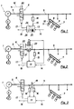
- a pressure medium source 1 is, for example. in the form of a driven by a motor 2, one Pressure accumulator 3 filling pressure medium pump 4 is provided.
- the pressure medium line 5 is preferably electromagnetic controllable 3/3-way valve 6 switched on.
- loading devices 7 connected, of which only one largely in the figures is shown schematically. These loading devices can, for example, be designed as tubular pressure elements 8 be embedded in rigid support arms 9 and over Pressure shoes 10 top rollers 11 of a drafting system 12 against Press lower rollers. There is only one in each of the figures Load device 7 shown, it is understood that a Drafting system a variety of such loading devices having.
- the pressure medium line 5 therefore necessarily also has one Plenty of connection points and - because the support arms 9 can be opened are - flexible hose connections. These components the pressure medium line 5 are inevitable with leaks contaminated, which represent leakage points through which continuously a more or less large amount of pressure medium - in usually air - escapes and must be replaced. If the Leakage losses must exceed a certain level on this Attention made to the fact and, if necessary, the machine be shut down automatically to reduce quality on to avoid generated yarn.
- a device 13 which is generally spoken as Computer is formed and a setpoint via a line 14 can be entered and via a line 15 Actual value of the pressure in the pressure medium line 5 is supplied, which is determined by a pressure gauge 16 lying against it becomes.
- the Device 13 an actuating signal, which via a line 17 Valve 6 is pushed open. This control signal is so generates that it is the valve 6 in the sense of an adjustment of the Actual pressure to the target pressure in the pressure medium line 4 influenced.
- the device 13 Unless intervenes and the pressure continues to below a second Limit drops or the pressure, for example, due to the bursting of a connecting hose suddenly below this second limit drops to fear under the loss of quality of the yarn are, the device 13 emits an interference signal, by which the Machine can be stopped automatically.
- the prewarning signal can trigger an optical or acoustic alarm signal which draws the operator's attention to the leak.
- This alarm signal can also be set in addition to the fault signal leading to the machine being stopped in order to inform the operator of the reason for the machine being stopped.
- the output of a pre-warning or interference signal when the setpoint pressure is not reached in the pressure medium line 5 has the advantage that it not only detects leakage losses, but also other errors that cause the setpoint pressure not to be reached, for example insufficient pressure medium supply through the pressure medium source 1.
- the device 13 opens when the pressure drops the pressure medium line 5, the valve 6 further.
- the open position the valve 6 is therefore a measure of the amount of leakage loss.
- the device 13 monitors the size of the control signal to the valve 6 and gives when this control signal Limit value exceeds, the pre-warning or the interference signal.
- the position of the valve 6 directly, so not over that control signal passed through the device 13 to the valve 6 to monitor.
- the valve 6 is dashed with a in Fig. 1 indicated position sensor 20 provided when reached an adjustable limit position of the valve via the Line 19 'emits the prewarning or the interference signal.
- Fig. 2 In the embodiment of Fig. 2 is in the pressure medium line 5 inserted a flow meter 21, which with the device 13 connected is.
- the function is such that the device 13 emits a warning or a fault signal if, after filling the Pressure medium line 5 of the flow meter 21 of the device 13 continues to report an inflow of pressure medium, which the adjustable limit values and thus excessive Indicates leakage.
- the flow meter 21 also represents an obstacle to that Flow of the pressure medium.
- This flow obstacle affects the filling of the pressure medium line 5, since it Inflow of the pressure medium is delayed.
- the flow meter 21 preferably a bypass 22 assign in the form of a 2/2-way valve 23.
- This directional valve 23 is preferably controllable by the device 13 and is through this when filling the pressure medium line 5 open.
- the pressure medium can be bypassed Flow meter 21 quickly into the pressure medium line 5th flow in. It is understood that such a bypass 22 with Advantage also associated with the flow resistance 18 of FIG. 3 can be.
- FIG. 3 shows an embodiment of the flow meter 21. It includes one in the Pressure medium line 5 arranged flow resistance 18, for example. in the form of an aperture and a pressure gauge 16 and 16 'each and behind the bezel.
- flow resistance 18 for example. in the form of an aperture
- a pressure gauge 16 and 16 'each and behind the bezel When pressure medium flows into the Pressure medium line 5 builds up a pressure drop at the orifice which is a function of flow. This pressure drop is detected by the two pressure meters 16, 16 'and the Device 13 fed. Calculated from the supplied signals the device gives the flow and gives as above described when a limit value of the A warning or a disturbance signal.
- the pressure gauge 16 of FIG. 3 can also be the pressure gauge be, according to the device 13, the position of the Valve 6 controls. Control or regulating valves are also known, in which the function of the device 13 are integrated. Such a valve therefore only needs the setpoint and the Actual value to be supplied, according to which it is then the Flow to maintain pressure in the Pressure medium line 5 regulates.
- the device 13 can also with an input device in the form of a keyboard 25 be provided, by means of which further data can be entered and opened a display device 26 are controllable such as. Spinning parameters relevant to working pressure and leakage like about fineness of the spun yarn, staple length of the spun Fibers, pinch line spacing of the drafting rollers and the like.
- the data records thus formed can be used as Control program of the device can be called again and do not have to be worked out or entered each time.
- a spinning machine after a Standstill at least after a change of the Spin data can only be put into operation again, when a record of data storage 24 is activated or the Activation of a data record has been confirmed. To this In this way it can be largely avoided that games with incorrect limits for the leakage are spun.
- the data memory can also be designed so that it recorded pressure, valve position or flow values as Leakage values can be read back. This makes it possible Long-term trends in changing the leakage of a Detect drafting device and intervene before the limit values can be achieved.
Landscapes
- Physics & Mathematics (AREA)
- Engineering & Computer Science (AREA)
- General Physics & Mathematics (AREA)
- Fluid Mechanics (AREA)
- Mechanical Engineering (AREA)
- Textile Engineering (AREA)
- Spinning Or Twisting Of Yarns (AREA)
Applications Claiming Priority (2)
| Application Number | Priority Date | Filing Date | Title |
|---|---|---|---|
| DE19652372 | 1996-12-17 | ||
| DE19652372A DE19652372A1 (de) | 1996-12-17 | 1996-12-17 | Pneumatische Belastungsvorrichtung eines Streckwerkes in einer Spinnmaschine |
Publications (3)
| Publication Number | Publication Date |
|---|---|
| EP0849383A2 true EP0849383A2 (fr) | 1998-06-24 |
| EP0849383A3 EP0849383A3 (fr) | 1999-04-07 |
| EP0849383B1 EP0849383B1 (fr) | 2001-09-12 |
Family
ID=7814921
Family Applications (1)
| Application Number | Title | Priority Date | Filing Date |
|---|---|---|---|
| EP97121805A Expired - Lifetime EP0849383B1 (fr) | 1996-12-17 | 1997-12-11 | Dispositif pneumatique pour charger un système d'étirage dans un métier à filer |
Country Status (4)
| Country | Link |
|---|---|
| US (1) | US5873230A (fr) |
| EP (1) | EP0849383B1 (fr) |
| JP (1) | JPH10226931A (fr) |
| DE (2) | DE19652372A1 (fr) |
Families Citing this family (15)
| Publication number | Priority date | Publication date | Assignee | Title |
|---|---|---|---|---|
| US6099264A (en) | 1998-08-27 | 2000-08-08 | Itt Manufacturing Enterprises, Inc. | Pump controller |
| DE10233135A1 (de) * | 2002-07-20 | 2004-02-12 | Smc Pneumatik Gmbh | Einrichtung zum Reduzieren des Verbrauchs von gasförmigen Medien in druckgasbetriebenen Anlagen |
| DE102004052510A1 (de) * | 2004-10-21 | 2006-04-27 | Wilhelm Stahlecker Gmbh | Luftdüsenspinnmaschine |
| DE102005050904B4 (de) * | 2005-10-21 | 2019-12-12 | Trützschler GmbH & Co Kommanditgesellschaft | Vorrichtung an einer Spinnereivorbereitungsmaschine, insbesondere Karde, Krempel o dgl., zur Überwachung |
| DE102014103238A1 (de) * | 2014-03-11 | 2015-10-01 | Nowtronic Gmbh | Vorrichtung und Verfahren zur Sicherheitsabsperrung von Flüssiggasanlagen |
| US10697848B1 (en) * | 2016-12-12 | 2020-06-30 | Kirk A. Dobbs | Smart building water supply management system with leak detection and flood prevention |
| US10670490B2 (en) * | 2017-11-28 | 2020-06-02 | Ge Healthcare Bio-Sciences Corp. | Measurement system and method therefore |
| DE102018125547A1 (de) * | 2018-10-15 | 2020-04-16 | TRüTZSCHLER GMBH & CO. KG | Druckregelung an einem Streckwerk |
| DE102019116234A1 (de) * | 2019-06-14 | 2020-12-17 | Saurer Intelligent Technology AG | Spinnmaschine |
| DE102019210600B4 (de) | 2019-07-18 | 2021-08-05 | Festo Se & Co. Kg | Diagnoseeinrichtung, Reglervorrichtung, fluidisches System und Verfahren zur Diagnose von Druckfluid-Leckage |
| DE102019123658A1 (de) * | 2019-09-04 | 2021-03-04 | Andritz Küsters Gmbh | Verfahren zur Überwachung von Dichtungselementen einer fluidisch betätigten Walzenanordnung sowie Walzenanordnung |
| DE102020115287A1 (de) | 2020-06-09 | 2021-12-09 | Maschinenfabrik Rieter Ag | Verfahren zur Detektion von Leckagen in einem fluidischen Leitungsnetz einer Spinn- oder Spulmaschine |
| CN112647171B (zh) * | 2020-12-28 | 2023-10-27 | 湖北智盛纺织科技有限公司 | 一种棉纺机牵伸罗拉加压装置的报警机构及其使用方法 |
| CN114967577B (zh) * | 2022-07-29 | 2022-10-21 | 扬州市安宜阀门有限公司 | 一种用于气瓶的安全控制系统及基于其的控制方法 |
| WO2024132128A1 (fr) * | 2022-12-21 | 2024-06-27 | Trützschler Group SE | Procédé de détection préventive d'un arrêt dans un système d'étirage d'un métier à filer, et système d'étirage d'un métier à filer |
Family Cites Families (8)
| Publication number | Priority date | Publication date | Assignee | Title |
|---|---|---|---|---|
| JPS5915520A (ja) * | 1982-07-15 | 1984-01-26 | Toyoda Autom Loom Works Ltd | ドラフト機構のロ−ラ加圧装置 |
| DE8521340U1 (de) * | 1985-07-24 | 1985-08-29 | SKF Textilmaschinen-Komponenten GmbH, 7000 Stuttgart | Ringspinnmaschine mit pneumatisch belasteten Oberwalzen |
| JPS62257426A (ja) * | 1986-04-25 | 1987-11-10 | Toray Ind Inc | 紡機のドラフトロ−ラ繊維巻付きによる停止方法および紡機 |
| DE3810998A1 (de) * | 1988-03-31 | 1989-10-19 | Eckardt Ag | Verfahren zur erfassung von aenderungen einer vorgegebenen geometrie eines durchstroemten rohrleitungsnetzes |
| IL90789A0 (en) * | 1988-08-05 | 1990-01-18 | Rieter Ag Maschf | Textile machine with drawframes |
| DE4215682B4 (de) * | 1991-06-04 | 2004-07-22 | Rieter Ingolstadt Spinnereimaschinenbau Ag | Verfahren und Vorrichtung zur Korrektur des Reguliereinsatzpunktes und der Regulierintensität |
| DE29609348U1 (de) * | 1996-05-24 | 1996-08-14 | Zinser Textilmaschinen Gmbh, 73061 Ebersbach | Pneumatische Belastungsvorrichtung eines Streckwerkes in einer Spinnmaschine |
| US5761772A (en) * | 1996-07-19 | 1998-06-09 | North Carolina State University | Securing and pressuring system for drafting rollers for automated textile drafting system |
-
1996
- 1996-12-17 DE DE19652372A patent/DE19652372A1/de not_active Withdrawn
-
1997
- 1997-12-10 JP JP9340237A patent/JPH10226931A/ja not_active Withdrawn
- 1997-12-11 EP EP97121805A patent/EP0849383B1/fr not_active Expired - Lifetime
- 1997-12-11 DE DE59704599T patent/DE59704599D1/de not_active Expired - Fee Related
- 1997-12-12 US US08/989,712 patent/US5873230A/en not_active Expired - Fee Related
Also Published As
| Publication number | Publication date |
|---|---|
| EP0849383B1 (fr) | 2001-09-12 |
| EP0849383A3 (fr) | 1999-04-07 |
| DE59704599D1 (de) | 2001-10-18 |
| US5873230A (en) | 1999-02-23 |
| JPH10226931A (ja) | 1998-08-25 |
| DE19652372A1 (de) | 1998-06-18 |
Similar Documents
| Publication | Publication Date | Title |
|---|---|---|
| EP0849383B1 (fr) | Dispositif pneumatique pour charger un système d'étirage dans un métier à filer | |
| DE102019135815B3 (de) | Wasserlöschanlage, Steuereinrichtung, Gefahrenmeldezentrale, Verfahren zum Steuern eines Pumpentestlaufs in einer Wasserlöschanlage und Verwendung einer Fluidumleitung in einer Wasserlöschanlage für einen Pumpentestlauf einer Pumpe | |
| DE4016004C2 (de) | Leckageüberwachung eines bei im Bergbau unter Tage einzusetzenden Arbeitsmaschinen eingerichteten hydraulischen Antriebssystems | |
| EP0284785B1 (fr) | Méthode et dispositif pour le contrôle de l'étanchéité de deux vannes disposées successivement sur un conduit de fluide | |
| DE3108247C2 (fr) | ||
| DE3918294C2 (de) | Verfahren zum Überwachen der Arbeitsweise und des Ausganges einer Abwasser-Pumpstation | |
| DE4229834A1 (de) | Verfahren und einrichtung zum elektrischen verarbeiten von vakuumdruckinformation fuer eine vakuumeinheit | |
| DE60102520T2 (de) | Verfahren und Vorrichtung zum Warnen eines Bedieners eines Fahrzeugs | |
| DE2610769C2 (de) | Auslaufschutzvorrichtung für ein Leitungssystem | |
| EP2483190B1 (fr) | Procédé d'établissement d'une limite de nettoyage sur une installation de nettoyage de fil | |
| EP0184836A2 (fr) | Méthode et dispositif pour le test d'étanchéité de deux soupapes d'arrêt dans une conduite à gaz | |
| DE212012000270U1 (de) | Vorrichtung zur vollständigen Überwachung des sekundären Drucks in einem hydrostatischen Stützsystem | |
| DE2834213C2 (de) | Vorrichtung zum Messen des Flüssigkeitspegels in einem Fahrzeugtank | |
| DE4229833A1 (de) | Druckinformation-verarbeitungseinrichtung zur verwendung in einer vakuumeinheit | |
| EP1960017B1 (fr) | Procédé de purge d'un filtre hydrophobe mouillé et dispositif de réalisation du procédé | |
| DE2350878B2 (de) | Abschaltvorrichtung fuer einen kernreaktor | |
| EP1283289B1 (fr) | Procédé et appareil de régulation de la capacité d'aspiration d'un dispositif d'aspiration de fils cassés d'une machine textile | |
| DE69802362T2 (de) | Elektronische Lenkvorrichtung für Baumaschinen | |
| DE102008040992A1 (de) | Saugsystem für eine Offenendspinnmaschine | |
| CH669412A5 (fr) | ||
| EP0866233A2 (fr) | Dispositif de surveillance du fonctionnement et d'immobilation pour une glissière de charriot avec palier à air | |
| EP1627693B1 (fr) | Dispositif de nettoyage et/ou de désinfection des corps creux, en particulier des tubes médicaux et des cathéters | |
| EP1568653A2 (fr) | Système de contrôle de ventilation pour citernes de carburants | |
| DE3644942A1 (de) | Verfahren zur veraenderung des niveaus einer auf wenigstens zwei hydraulikzylindern abgestuetzten einrichtung | |
| EP1079292A1 (fr) | Régulateur de pression de gaz |
Legal Events
| Date | Code | Title | Description |
|---|---|---|---|
| PUAI | Public reference made under article 153(3) epc to a published international application that has entered the european phase |
Free format text: ORIGINAL CODE: 0009012 |
|
| AK | Designated contracting states |
Kind code of ref document: A2 Designated state(s): CH DE IT LI |
|
| AX | Request for extension of the european patent |
Free format text: AL;LT;LV;MK;RO;SI |
|
| PUAL | Search report despatched |
Free format text: ORIGINAL CODE: 0009013 |
|
| AK | Designated contracting states |
Kind code of ref document: A3 Designated state(s): AT BE CH DE DK ES FI FR GB GR IE IT LI LU MC NL PT SE |
|
| AX | Request for extension of the european patent |
Free format text: AL;LT;LV;MK;RO;SI |
|
| 17P | Request for examination filed |
Effective date: 19990928 |
|
| AKX | Designation fees paid |
Free format text: CH DE IT LI |
|
| 17Q | First examination report despatched |
Effective date: 19991130 |
|
| GRAG | Despatch of communication of intention to grant |
Free format text: ORIGINAL CODE: EPIDOS AGRA |
|
| GRAG | Despatch of communication of intention to grant |
Free format text: ORIGINAL CODE: EPIDOS AGRA |
|
| GRAH | Despatch of communication of intention to grant a patent |
Free format text: ORIGINAL CODE: EPIDOS IGRA |
|
| GRAH | Despatch of communication of intention to grant a patent |
Free format text: ORIGINAL CODE: EPIDOS IGRA |
|
| GRAA | (expected) grant |
Free format text: ORIGINAL CODE: 0009210 |
|
| AK | Designated contracting states |
Kind code of ref document: B1 Designated state(s): CH DE IT LI |
|
| REG | Reference to a national code |
Ref country code: CH Ref legal event code: EP |
|
| REF | Corresponds to: |
Ref document number: 59704599 Country of ref document: DE Date of ref document: 20011018 |
|
| PLBE | No opposition filed within time limit |
Free format text: ORIGINAL CODE: 0009261 |
|
| STAA | Information on the status of an ep patent application or granted ep patent |
Free format text: STATUS: NO OPPOSITION FILED WITHIN TIME LIMIT |
|
| 26N | No opposition filed | ||
| PGFP | Annual fee paid to national office [announced via postgrant information from national office to epo] |
Ref country code: CH Payment date: 20031219 Year of fee payment: 7 |
|
| PGFP | Annual fee paid to national office [announced via postgrant information from national office to epo] |
Ref country code: DE Payment date: 20040205 Year of fee payment: 7 |
|
| PG25 | Lapsed in a contracting state [announced via postgrant information from national office to epo] |
Ref country code: LI Free format text: LAPSE BECAUSE OF NON-PAYMENT OF DUE FEES Effective date: 20041231 Ref country code: CH Free format text: LAPSE BECAUSE OF NON-PAYMENT OF DUE FEES Effective date: 20041231 |
|
| PG25 | Lapsed in a contracting state [announced via postgrant information from national office to epo] |
Ref country code: DE Free format text: LAPSE BECAUSE OF NON-PAYMENT OF DUE FEES Effective date: 20050701 |
|
| REG | Reference to a national code |
Ref country code: CH Ref legal event code: PL |
|
| PG25 | Lapsed in a contracting state [announced via postgrant information from national office to epo] |
Ref country code: IT Free format text: LAPSE BECAUSE OF NON-PAYMENT OF DUE FEES Effective date: 20051211 |