EP0849389B1 - Drehbare Vorrichtung zum Nadeln und Halter zum Herstellen von vernadelten Faserstrukturen - Google Patents
Drehbare Vorrichtung zum Nadeln und Halter zum Herstellen von vernadelten Faserstrukturen Download PDFInfo
- Publication number
- EP0849389B1 EP0849389B1 EP97120448A EP97120448A EP0849389B1 EP 0849389 B1 EP0849389 B1 EP 0849389B1 EP 97120448 A EP97120448 A EP 97120448A EP 97120448 A EP97120448 A EP 97120448A EP 0849389 B1 EP0849389 B1 EP 0849389B1
- Authority
- EP
- European Patent Office
- Prior art keywords
- needle penetrable
- face
- sheet
- multitude
- base ring
- Prior art date
- Legal status (The legal status is an assumption and is not a legal conclusion. Google has not performed a legal analysis and makes no representation as to the accuracy of the status listed.)
- Expired - Lifetime
Links
- 238000000034 method Methods 0.000 title claims abstract description 53
- 238000009950 felting Methods 0.000 claims abstract description 41
- 238000000151 deposition Methods 0.000 claims abstract description 8
- 239000000835 fiber Substances 0.000 description 23
- 239000002657 fibrous material Substances 0.000 description 8
- 229920002239 polyacrylonitrile Polymers 0.000 description 7
- 229920000742 Cotton Polymers 0.000 description 6
- 241000254043 Melolonthinae Species 0.000 description 5
- 229920001971 elastomer Polymers 0.000 description 5
- 239000000463 material Substances 0.000 description 5
- 230000007246 mechanism Effects 0.000 description 5
- 239000000919 ceramic Substances 0.000 description 4
- 229920003023 plastic Polymers 0.000 description 4
- 239000004033 plastic Substances 0.000 description 4
- OKTJSMMVPCPJKN-UHFFFAOYSA-N Carbon Chemical compound [C] OKTJSMMVPCPJKN-UHFFFAOYSA-N 0.000 description 3
- 229920000049 Carbon (fiber) Polymers 0.000 description 3
- 239000004917 carbon fiber Substances 0.000 description 3
- 239000000806 elastomer Substances 0.000 description 3
- 239000000203 mixture Substances 0.000 description 3
- 239000002243 precursor Substances 0.000 description 3
- 229910052799 carbon Inorganic materials 0.000 description 2
- 239000002131 composite material Substances 0.000 description 2
- 230000013011 mating Effects 0.000 description 2
- 239000002184 metal Substances 0.000 description 2
- 229910052751 metal Inorganic materials 0.000 description 2
- 239000005060 rubber Substances 0.000 description 2
- 239000004753 textile Substances 0.000 description 2
- 229920002430 Fibre-reinforced plastic Polymers 0.000 description 1
- 239000004677 Nylon Substances 0.000 description 1
- 239000004952 Polyamide Substances 0.000 description 1
- 229910000831 Steel Inorganic materials 0.000 description 1
- 238000010420 art technique Methods 0.000 description 1
- 230000004888 barrier function Effects 0.000 description 1
- 239000007833 carbon precursor Substances 0.000 description 1
- 238000005056 compaction Methods 0.000 description 1
- 230000006835 compression Effects 0.000 description 1
- 238000007906 compression Methods 0.000 description 1
- 238000010276 construction Methods 0.000 description 1
- 238000005520 cutting process Methods 0.000 description 1
- 239000004744 fabric Substances 0.000 description 1
- 239000011151 fibre-reinforced plastic Substances 0.000 description 1
- 229910002804 graphite Inorganic materials 0.000 description 1
- 239000010439 graphite Substances 0.000 description 1
- 230000008595 infiltration Effects 0.000 description 1
- 238000001764 infiltration Methods 0.000 description 1
- 238000009434 installation Methods 0.000 description 1
- 238000004519 manufacturing process Methods 0.000 description 1
- 239000011159 matrix material Substances 0.000 description 1
- 150000002739 metals Chemical class 0.000 description 1
- VNWKTOKETHGBQD-UHFFFAOYSA-N methane Chemical compound C VNWKTOKETHGBQD-UHFFFAOYSA-N 0.000 description 1
- 238000009952 needle felting Methods 0.000 description 1
- 239000004745 nonwoven fabric Substances 0.000 description 1
- 229920001778 nylon Polymers 0.000 description 1
- 230000035515 penetration Effects 0.000 description 1
- 229920002647 polyamide Polymers 0.000 description 1
- 239000010959 steel Substances 0.000 description 1
- 239000002759 woven fabric Substances 0.000 description 1
Images



Classifications
-
- D—TEXTILES; PAPER
- D05—SEWING; EMBROIDERING; TUFTING
- D05B—SEWING
- D05B39/00—Workpiece carriers
-
- D—TEXTILES; PAPER
- D04—BRAIDING; LACE-MAKING; KNITTING; TRIMMINGS; NON-WOVEN FABRICS
- D04H—MAKING TEXTILE FABRICS, e.g. FROM FIBRES OR FILAMENTARY MATERIAL; FABRICS MADE BY SUCH PROCESSES OR APPARATUS, e.g. FELTS, NON-WOVEN FABRICS; COTTON-WOOL; WADDING ; NON-WOVEN FABRICS FROM STAPLE FIBRES, FILAMENTS OR YARNS, BONDED WITH AT LEAST ONE WEB-LIKE MATERIAL DURING THEIR CONSOLIDATION
- D04H18/00—Needling machines
-
- D—TEXTILES; PAPER
- D04—BRAIDING; LACE-MAKING; KNITTING; TRIMMINGS; NON-WOVEN FABRICS
- D04H—MAKING TEXTILE FABRICS, e.g. FROM FIBRES OR FILAMENTARY MATERIAL; FABRICS MADE BY SUCH PROCESSES OR APPARATUS, e.g. FELTS, NON-WOVEN FABRICS; COTTON-WOOL; WADDING ; NON-WOVEN FABRICS FROM STAPLE FIBRES, FILAMENTS OR YARNS, BONDED WITH AT LEAST ONE WEB-LIKE MATERIAL DURING THEIR CONSOLIDATION
- D04H18/00—Needling machines
- D04H18/02—Needling machines with needles
Definitions
- the invention relates to the field of producing fibrous structures by a needling process. More particularly, the invention relates to rotary needle processes in which a multitude of forked or barbed needles are repeatedly driven into a fibrous structure disposed on a bedplate as the fibrous structure is rotated about an axis of rotation.
- Rotary needling processes and machinery are well known in the textile arts. According to one type of prior art process, a multitude of forked or barbed needles are repeatedly driven into a fibrous structure disposed on a planar surface of a needle penetrable support as the support is rotated about an axis of rotation perpendicular to the planar surface. Examples are described in US-A-5,217,770, US-A- 4,955,123, EP-A-0424988, and DE-A-2911762.
- This particular type of rotary needling process may be employed to make circular and annular fibrous structures, and has been found to be quite useful for making aircraft brake disk preforms suitable for subsequent processing into composite aircraft brake disks, such subsequent processing including infiltration of a binding matrix according to various methods well known in the relevant art.
- the needle penetrable support comprises a needle penetrable medium (for example, plastic, elastomer, foamed plastic or elastomer, or brush bristles) that defines a planar surface upon which fibrous material is deposited as needling support is rotated about an axis of rotation perpendicular to the planar surface.
- a needle penetrable medium for example, plastic, elastomer, foamed plastic or elastomer, or brush bristles
- the fibrous material first deposited on the planar surface is cohered with the needle penetrable medium in order to cause the fibrous material to move with the needle support as additional fibrous material is added until a cohered fibrous structure having a desired final thickness is produced.
- the fibrous structure is subsequently removed from the support by either peeling, prying, or cutting it from the needle penetrable medium.
- Peeling the fibrous structure from the needle penetrable medium is undesirable with certain thick fibrous structures, such as aircraft brake disk preforms, because it distorts and often damages the fibrous structure. If distortion and damage is of concern, then the fibrous structure is cut from the needle penetrable medium. However, the latter approach leaves residual fibrous material in the needle penetrable medium which must be removed before making another fibrous structure, which is tedious and time consuming.
- It is the object of the invention is to provide a needling process wherein the fibrous material deposited on the support is fixed to the support with sufficient strength to remain fixed through completion of the fibrous structure, but can be easily removed upon completion, with minimum residual of fibrous material at the support.
- a rotary needling support 10 is provided, according to an aspect of the invention.
- the rotary needling support 10 comprises a bedplate 11 that defines a face 18 having a needle penetrable area, and an outer base ring 26 encircling the face 18, the outer base ring 26 being rotatable around an axis of rotation 14, preferably perpendicular to the face 18.
- the base ring 26 may be formed as an integral part of the bedplate 11, or as a separate piece.
- the needle penetrable area is coextensive with the face 18, but the needle penetrable area may occupy only a portion of the face 18.
- a needle penetrable sheet 22 covers the face 18 and is attached to the outer base ring 26 such that the needle penetrable sheet 22 rotates beneath a needling head 54.
- the needling head 54 comprises a multitude of felting needles 20 mounted in a needle board 24, the felting needles 20 being repeatedly driven into the needle penetrable sheet 22 and the needle penetrable area of the face 18 during at least a portion of the rotary needle felting process, as the needle penetrable sheet 22 rotates beneath the needling head 54
- felting needles refers to forked or barbed needles that are repeatedly driven into a fibrous structure to increase entanglement and compaction of the fibrous structure, such process being very well known in the art. Suitable felting needles are available from Groz-Beckert, Germany, and Foster Needle Co., Inc., Wisconsin, U.S.A.
- the needle penetrable sheet 22 acts, in part, as a carrier upon which fibrous layers are deposited and cohered by the action of the multitude of felting needles 20.
- the felting needles 20 are forked or barbed, as is known in the art, which causes the felting needles 20 to transport fiber within the fibrous layers.
- the needling head may take various shapes depending on the desired needling action, but generally extends across the full width of the fibrous layers to be needled, the "width" being perpendicular to the direction the fibrous layers are passed beneath the needle head 54. Multiple needling heads may be employed, each head having a width corresponding to the width of the fibrous layers or less than the width of the fibrous layers. Likewise, the needling head 54 may cover just a portion of the circumference of the face 18 as shown in Figure 1, or the entire circumference of the face 18. Any such variations are considered to fall within the purview of the invention.
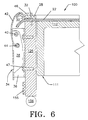
- FIG. 1-6 Two embodiments for driving the needle penetrable sheet 22 are presented in Figures 1-6.
- the needling head 54 is reciprocated in a manner well known in the art by a suitable mechanism.
- the needling support may be raised and lowered relative to the felting needles parallel to the axis of rotation by an appropriate mechanism, such as a powered jackscrew.
- the rotary needling support and needling head are attached to a frame, along with drive and control mechanisms.
- Rotary needling machinery and processes that may employ the rotary needling support according to the invention are known in the art, examples of which are described in US-A-5,217,770, US-A-4,955,123, EP-A-0424988, and DE-A-2911762. A detailed description of such machinery is not necessary here.
- the bedplate 11 comprises a base 12 rotatable about the axis of rotation 14 during the needling process, and a needle penetrable area beneath the multitude of felting needles 20.
- the needle penetrable area covers essentially all of face 18 since the entire face is passed beneath the multitude of felting needles 20.
- the needle penetrable area may be an array of holes (not shown) or concentric grooves (not shown) in the base 12 aligned with the felting needles 20, or a needle penetrable medium 16 may be attached to the base 12, with the latter being preferred since it eliminates the need to align the felting needles 20 with holes or grooves in the base 12.
- the needle penetrable medium 16 superposes a portion of the base 12 and defines the face 18, which may be perpendicular to the axis of rotation 14.
- the face 18 may be planar or non-planar, such as concave or convex, depending on the particular needling process and the desired shape of the fibrous structure made by the process.
- the needle penetrable sheet 22 (shown with a portion broken away to expose the face 18) superposes the needle penetrable medium 16 and is removably fixed to the base 12 outside the face 18 in a manner that will be described in more detail.
- the base 12, the needle penetrable medium 16, the face 18, and the needle penetrable sheet 22 are circular about the axis of rotation 14, and are more preferably annular about the axis of rotation 14. If the face 18 is annular, the needle penetrable sheet 22 may be attached outside the face 18 adjacent the outside diameter of the face 18, adjacent the inside diameter of the face 18, or both. Essentially the entire face 18 is passed beneath the needle board 24 and is subjected to penetration by the multitude of felting needles 20 during at least a portion of the needling process, and normally occurs at the beginning of the process.
- a first fibrous layer 48 and one or more additional fibrous layers 50 are superposed over the needle penetrable medium 16 and the needle penetrable sheet 22, and subjected to one or more needling passes, as will be described in more detail.
- the fibrous layers 48 and 50 may take various forms. For making disks or annuli, the fibrous layers may be shaped as sectors of a disk or annulus, or the fibrous layers may be formed as a helical tape. Examples are provided in US-A-5,546,880, US-A-5,417,138, US-A-5,217,770 and US-A-4,955,123.
- the fibrous layers may comprise many types of fibers, including carbon and ceramic fibers, and precursors of carbon and ceramic fibers, and mixtures of these.
- Polyacrylonitrile (PAN) fiber, oxidized polyacrylonitrile fiber (OPF) are examples of carbon fiber precursors.
- the individual fibrous layers 48 and 50 may be formed, without limitation, from tows, yarns, woven and non-woven fabrics, knit fabrics and felts.
- the term “tow” is used to refer to a strand of continuous filaments.
- the term “yarn” is used to refer to a continuous strand of continuous or staple fibers or blends of these.
- various forms of continuous or discontinuous fiber may be employed to form the fibrous layers 48 and 50.
- the needle penetrable sheet 22 is clamped to the base 12. This is preferably accomplished by providing an outer base ring 26 encircling the surface 18 and fixed to the base 12.
- the needle penetrable sheet 22 superposes the outer base ring 26.
- An outer retaining ring 28 superposes the outer base ring 26 and clamps the needle penetrable sheet 22 therebetween.
- the outer retaining ring 28 and outer base ring 26 grips the needle penetrable sheet 22.
- the outer base ring 26 may comprise a plurality of pointed pins 30 protruding from the outer base ring 26 parallel to the axis of rotation 14.
- the needle penetrable sheet 22 superposes the outer base ring 26 and is impaled by the pins 30.
- the outer retaining ring 28 has a plurality of mating holes 32 that register with and receive the pointed pins 30 when the outer retaining ring 28 is placed over the outer base ring 26.
- a multitude of pins 30 and holes 32 are preferably provided, evenly spaced around the circumference of the rings 26 and 28.
- Other techniques for gripping the needle penetrable sheet 22 are contemplated in the practice of the invention, for example providing a serrated face on the outer retaining ring 28 and a rubber surface on the outer base ring 26, the needle penetrable sheet 22 being clamped between the serrated face and the rubber surface.
- the outer base ring 26 may be removably attached to the base 12 by a plurality of threaded fasteners (not shown) that pass through a plurality of holes in the outer base ring 26 and engage mating threaded holes (not shown) in the base 12, or other suitable means.
- a plurality of threaded fasteners not shown
- mating threaded holes not shown
- Various means of gripping the needle penetrable sheet 22 outside the face 18 are apparent to persons skilled in the art in light of the disclosure provided herein, any of which are considered to fall within the purview of the invention.
- An inner base ring 27 (shown in dashed lines) and inner retaining ring 29 (shown in dashed lines), both shown with a portion broken away, may be employed to attach the needle penetrable sheet 22 to the base 12 adjacent the inside diameter of the face 18, the inner base ring 27 and inner retaining ring 29 having the same features described herein in relation to outer base ring 26 and outer retaining ring 28.
- the face 18 encircles the inner retaining ring 29 and inner base ring 27. Attaching the needle penetrable sheet 22 adjacent the outside diameter is preferred.
- the base 12 is configured to be driven with the outer base ring 26, both components being rotated about the axis of rotation 14 by suitable drive means (not shown), such drive means being known in the art for rotary needling processes.
- Driving the base 12 and the outer base ring 26 together is preferred because the needle penetrable sheet 22 is driven by frictional engagement with the base 12 as well as mechanical engagement with the outer base ring 26, which reduces stress on the sheet 22 where it attaches to the ring 26.
- the needle penetrable medium 16 is preferably attached to the base, and may be permanently fixed to the base 12.
- the needle penetrable medium 16 comprises brush bristles 52 fixed to the base 12, as shown in Figure 3.
- the needle penetrable medium 16 may also comprise a foamed elastomer and/or a foamed plastic.
- Nylon (polyamide) brush bristles 52 are preferred in the practice of the invention since they are more durable and reusable.
- the base 12 is preferably rigid, and may be formed from suitable materials, such as metals, plastics, and fiber reinforced plastics.
- the outer base ring 26, outer retaining ring 28, and pins 30 are preferably formed from a metal, such as steel.
- the needle penetrable sheet may be a fibrous sheet, and is preferably a woven fibrous sheet.
- a preferred embodiment of the invention for making aircraft brake disk preforms from oxidized polyacrylonitrile fiber (OPF) employs a 4,83g/cm 2 (14.25 ounce per square yard) cotton chafer for the needle penetrable sheet 22 having 23 warp ends per 2.54 cm (per inch) and 23 picks per 2.54 cm (per inch), and a cotton count of warp and filling of 2.5-2.75, available as Style G1250 from Eastbank Textiles/Eastbank Trading Co., Macon, Georgia, U.S.A., and manufactured by Walton Monroe Mills Inc., Monroe, Georgia, U.S.A.
- the cotton chafer works quite well in the practice of the invention because it acts as a good vehicle for bonding to fibrous layers 48 and 50 by receiving fiber transported from one or more of those layers, and has good strength for rotation with resistance to tearing.
- fibrous layers 48 and 50 by receiving fiber transported from one or more of those layers, and has good strength for rotation with resistance to tearing.
- other types of fibrous layers having similar characteristics is contemplated, including non-woven and knit materials, any of which are considered to fall within the purview of the invention.
- At least one needle penetrable sheet 22 is provided, and at least one additional needle penetrable sheet may be provided covering the face 18 and fixed to the rotary needling support 10 outside the face 18.
- two, three, or more needle penetrable sheets 22 may be provided superposed over each other and attached to the base 12 outside the face 18.
- Employing superposed needle penetrable sheets 22 is useful if needling is too aggressive and damages a single needle penetrable sheet 22. It has been found that superposing two or more sheets provides a support structure that can withstand more aggressive needling. Alternatively, the weight of the needle penetrable sheet may be increased rather than providing multiple superposed sheets. However, providing two or more needle penetrable sheets is more expedient because only one weight of material need be specified and maintained in stock.
- the needle penetrable sheet 22 may be clamped between the outer base ring 26 and outer retaining ring 28 by various means, including threaded fasteners and various clamping devices known in the mechanical arts such as spring loaded clamps, screw actuated clamps, pneumatic clamps, and hydraulic clamps.
- a certain embodiment utilizes a plurality of draw hasps 34 attached to the base 12. Referring again to Figure 3, the draw hasps 34 draw the outer retaining ring 28 toward the outer base ring 26 thereby clamping the needle penetrable sheet 22 therebetween.
- Draw hasp 34 comprises a hasp body 36, a hasp lever 38 pivotally attached to the hasp body 36 by a hasp pin 40, and a hasp clamp 42 pivotally attached to the hasp lever 38 by a damp pin 44. Pivoting the hasp lever 38 about the hasp pin 40 clockwise moves the clamp pin 44 clockwise, which moves the hasp clamp 42 upward and releases the outer retaining ring 28. The outer retaining ring 28 is clamped by pivoting the hasp lever 38 clockwise, which moves the hasp clamp 42 downward.
- a clamp tab 46 is preferably attached to the outer retaining ring 28 which cooperates with and engages the end of the hasp claim 42.
- the clamp tab 46 may be attached to the outer retaining ring 28 by suitable means, including screws, rivets, and welds.
- the draw hasp 36 may be attached to the base 12 by suitable means, including screws, rivets, and welds. Screws 47 are employed in the example presented in Figure 3.
- Rotary needling support 100 is similar to the rotary needling support 10 of Figures 1-2, and like components in the two embodiments are numbered alike.
- Rotary needling support 100 comprises a bedplate 111 having a base 112 that defines a face 118 having a needle penetrable area being an array of holes 113 in the base 112.
- the needle penetrable area corresponds to the area penetrated by the multitude of felting needles, which may be all or part of the face 118 depending on the shape of the needling head 54.
- a multitude of felting needles 20 are mounted in a needle board 24 disposed over the array of holes 113, with each hole being aligned with a respective needle 20.
- the needle penetrable area may also be comprised of an array of concentric grooves (not shown), or a needle penetrable medium such as a brush may be employed to define all of face 118, or just the portion beneath the multitude of felting needles 20.
- An outer base ring 126 encircles the face 118 and is free to rotate relative to the bedplate 111.
- the needle penetrable sheet 22 covers the face 118 and is attached to the outer base ring 126 in a manner previously described in relation to Figures 1-3.
- the bedplate 111 is fixed against rotation relative to the multitude of felting needles 20, and the needle penetrable sheet 22 is rotated by rotating the outer base ring 126.
- the needle penetrable sheet 22 slides over the face 118, which remains stationary, and the outer base ring 126 forces the needle penetrable sheet 22 to rotate with the outer base ring 126.
- a stronger needle penetrable sheet 22 may be employed in order to prevent the sheet from tearing away from the outer base ring 126 such as, for example, a heavier weight cotton chafer.
- An inner base ring may also be provided similar in construction and operation to outer base ring 126, the inner base ring being encircled by the face 118. The inner base ring may be driven with the outer base ring 126.
- the outer base ring 126 (and/or inner base ring) is supported, such as by bearings 156, and is forced to rotate by a motor 152, which is mechanically engaged to the outer base ring 126 by a suitable mechanism.
- a pulley 154 is attached to the motor shaft, and the outer base ring 126 (and/or inner base ring) is driven by a belt 155.
- a pinion may engage the inside or the outside of outer base ring 126 (and/or inner base ring).
- a ring gear may be provided on the outer base ring (and/or inner base ring) to engage the pinion.
- Other drive mechanisms are evident to persons skilled in the art of needling machinery, any of which are considered to fall within the purview of the invention.
- Needling support 200 is very similar to needling support 10, except that needling support 200 comprises a plurality of spring-loaded clamps 234 in place of the draw hasps 34.
- the spring loaded clamp 234 comprises a pair of guide brackets 236, and a clamp bar 238 received within the guide brackets 236.
- the clamp bar 238 comprises a shaft portion 240 and a finger portion 242.
- Each guide bracket 236 has a hole 244 in alignment with each other, and the shaft portion 240 is received in the holes 244 in a manner such that the shaft portion 240 may slide (translate) vertically within the guide brackets 236.
- the shaft portion 240 has a spring stop 246, and a spring 248 is disposed in compression between the stop 246 and the upper guide bracket 236.
- the spring 248 pulls the shaft portion 240 down, which drives the finger portion 242 onto the outer retaining ring 28, thereby providing a clamping force that clamps the needle penetrable sheet 22 between the outer retaining ring 28 and the outer base ring 26.
- the outer retaining ring 28 is released by lowering the needle penetrable support 200. As the support 200 is lowered, the end of the shaft portion 240 contacts a release stop 250, which stops the clamp bar 238 while the support 200 continues to lower, thereby causing the outer retaining ring 28 to move away from the finger portion 242.
- the release stop 250 is fixed to the frame (not shown) of the needling machine. With the needling support 200 lowered a predetermined distance, the clamps 234 release the outer retaining ring 28 and permit its installation or removal.
- the spring loaded clamp 234 be may employed with any embodiment of the invention described herein
- a rotary needling process is also provided, according to a further aspect of the invention.
- the process comprises the steps of removably fixing a needle penetrable sheet 22 to a rotary needling support 10, the rotary needling support 10 defining a face 18 disposed beneath a multitude of felting needles 20 and having a needle penetrable area, the needle penetrable sheet 22 covering the face and being fixed to the rotary needling support 10 outside the face 18; rotating the needle penetrable sheet 22 about an axis of rotation; depositing at least a first fibrous layer 48 on the needle penetrable sheet 22; cohering the first fibrous layer 48 and the needle penetrable sheet 22 by repeatedly driving the multitude of felting needles 20 into the first fibrous layer 48 and the needle penetrable sheet 22; and, removing the first fibrous layer 48 and the needle penetrable sheet from the rotary needling support subsequent to the first fibrous layer 48 and the needle penetrable sheet 22 being cohered.
- the process comprises the steps of superposing the needle penetrable sheet 22 over the needle penetrable medium 16 attached to the base 12, the needle penetrable medium 16 defining the planar face 18; removably fixing the needle penetrable sheet 22 to the base 12 outside the planar face 18; rotating the base 12 about the axis of rotation 14 perpendicular to the planar face 18; depositing at least a first fibrous layer 48 on the needle penetrable sheet 22; cohering the first fibrous layer 48 and the needle penetrable sheet 22 by repeatedly driving the multitude of felting needles 20 into the first fibrous layer 48 and the needle penetrable sheet 22; and removing the first fibrous layer 48 and the needle penetrable sheet 22 from the needle penetrable medium 16 subsequent the first fibrous layer 48 and the needle penetrable sheet 22 being cohered.
- the various features previously described in relation to Figures 1-7 may be employed in this process.
- the multitude of felting needles 20 penetrate the needle penetrable medium 16 during at least a portion of the step of cohering the first fibrous layer 48 and the needle penetrable sheet 22, without cohering the needle penetrable sheet 22 and the needle penetrable medium 16 or, stated differently, without adhering the needle penetrable sheet 22 to the face 18.
- a fibrous structure manufactured by employing this step is easily removable from the bed plate 11.
- a needle penetrable area comprising an array of holes 113 or an array of concentric grooves (not shown)
- fiber transported through the needle penetrable sheet 22 into the holes 113 or grooves (not shown) does not cause the needle penetrable sheet 22 to adhere to the face 18 because the fiber easily pulls from the holes or grooves.
- a brush 52 is employed as the needle penetrable medium 16
- the previously described cotton chafer needle penetrable sheet 22 greatly inhibits transport of fiber into the brush 52. Modulating needling parameters to reduce transport generally is not necessary because the cotton chafer acts as an effective barrier against fiber transport into the brush. Little, if any, fiber remains in the brush 52 after the fibrous sheet 22 is removed. The finish of the surface 18 of the brush 52 does not appear to affect the tendency of the needle penetrable sheet 22 to adhere to the brush 52.
- the process further comprises the steps of depositing a multitude of additional fibrous layers 50 on the first fibrous layer 48, and cohering the first fibrous layer 48 and the multitude of additional fibrous layers 50 by repeatedly driving the multitude of felting needles 20 into the first fibrous layer 48 and the multitude of additional fibrous layers 50.
- the latter step may be employed without driving the multitude of felting needles 20 into the first fibrous layer 48, or all the way through the multitude of additional fibrous layers 50, while cohering at least some of the additional fibrous layers 50.
- these layers are the middle and/or top additional fibrous layers 50, which is typical for relatively thick fibrous structures, such as aircraft brake disks.
- the multitude of felting needles 20 are driven into the needle penetrable medium 16 while cohering at least some of the fibrous layers 48 and 50 (typically at the beginning of the process), and the multitude of felting needles are not driven into the needle penetrable medium while cohering at least some of the fibrous layers 50 (typically at the middle and/or end of the process).
- Each of the layers 48 and 50 may be superposed and individually needled to one or more previous layers, or more than one layer may be superposed over one or more previous layers before being subjected to a needling pass.
- the fibrous layers 50 may, without limitation, be comprised of individual fibrous annuli, layers of sectors of annuli placed in side-by-side contiguous relationship, and/or helical fibrous strips (braided, woven, or knitted).
- the layers are preferably comprised of oxidized polyacrylonitrile fiber (OPF) for manufacture of aircraft brake disk preforms, although other materials may be employed depending on the desired final properties or the intended use of the final fibrous structure, such materials including polyacrylonitrile fiber (PAN), carbon fibers, graphite fibers, ceramic fibers, precursors of carbon fibers and precursors of ceramic fibers, and mixtures of these.
- PAN polyacrylonitrile fiber
- a process suitable for making thick annular fibrous structures comprising the steps of (a) superposing a fibrous sheet 22 over a needle penetrable medium 16 attached to a base 12, the needle penetrable medium 16 defining a planar face 18 and comprising a multitude of brush bristles; (b) removably fixing the fibrous sheet 22 to the base outside the planar face 18 by impaling the fibrous sheet 22 on a plurality of pins 30 fixed to the base 12 outside the planar surface 18 and clamping the fibrous sheet 22 to the base 16; (c) rotating the base 16 about an axis of rotation 14 perpendicular to the planar face 18; (d) depositing at least a first fibrous layer 48 on the fibrous sheet 22; (e) cohering the first fibrous layer 48 and the fibrous sheet 22 by repeatedly driving the multitude of felting needles 20 into the first fibrous layer 48 and the fibrous sheet 22; (f) deposit
Landscapes
- Engineering & Computer Science (AREA)
- Textile Engineering (AREA)
- Nonwoven Fabrics (AREA)
- Finger-Pressure Massage (AREA)
- Yarns And Mechanical Finishing Of Yarns Or Ropes (AREA)
Claims (19)
- Drehvernadelungsverfahren mit den folgenden Schritten:Vorsehen eines Drehvernadelungsträgers (10, 100, 200) mit einer unter einer Vielzahl von Verfilzungsnadeln (20) angeordneten Fläche (18, 118), die einen von Nadeln durchdringbaren Bereich aufweist,lösbares Befestigen wenigstens einer von Nadeln durchdringbaren Bahn (22) an dem Drehvernadelungsträger (10, 100, 200), wobei die von Nadeln durchdringbare Bahn (22) die Fläche (18, 118) bedeckt und an dem Drehvernadelungsträger (10, 100, 200) außerhalb der Fläche (18, 118) angebracht ist,Drehen der von Nadeln durchdringbaren Bahn (22) um eine Drehachse,Aufbringen wenigstens einer ersten Faserschicht auf der von Nadeln durchdringbaren Bahn (22),Verbinden der ersten Faserschicht (48) und der von Nadeln durchdringbaren Bahn (22) durch wiederholtes Treiben der mehreren Verfilzungsnadeln (20) in die erste Faserschicht (48) und die von Nadeln durchdringbare Bahn (22), undEntfernen der ersten Faserschicht (48) und der von Nadeln durchdringbaren Bahn (22) von dem Drehvernadelungsträger (10, 100, 200) nach dem Verbinden der ersten Faserschicht (48) mit der von Nadeln durchdringbaren Bahn (22).
- Verfahren nach Anspruch 1, bei dem die von Nadeln durchdringbare Bahn (22) nicht an der Fläche (18, 118) haftet.
- Verfahren nach Anspruch 1 oder 2, ferner mit den folgenden Schritten:Aufbringen mehrerer zusätzlicher Faserschichten (50) auf der ersten Faserschicht (48), undVerbinden der ersten Faserschicht (48) und der mehreren zusätzlichen Faserschichten (50) durch wiederholtes Treiben der mehrere Verfilzungsnadeln (20) in die erste Faserschicht (48) und die mehreren zusätzlichen Faserschichten (30).
- Verfahren nach einem der Ansprüche 1-3, bei dem der Drehvemadelungsträger (10, 100, 200) eine Basis (12, 112) und ein an der Basis (12, 112) angebrachtes von Nadeln durchdringbares Medium (16) aufweist, das die Fläche (18, 118) bildet.
- Verfahren nach einem der Ansprüche 1-3, bei dem der Drehvemadelungsträger (10, 100, 200) eine die Fläche (18, 118) bildende Basis (12, 112) und einen die Fläche (18, 118) einschließenden äußeren Basisring (26, 126) aufweist, wobei die von Nadeln durchdringbare Bahn (22) an dem äußeren Basisring (26, 126) angebracht ist, und wobei die von Nadeln durchdringbare Bahn (22) und die Basis (12, 112) mit dem äußeren Basisring (26, 126) gedreht werden.
- Verfahren nach einem der Ansprüche 1-3, bei dem der Drehvernadelungsträger (10, 100, 200) eine die Fläche (18, 118) bildende Basis (12, 112) und einen von der Fläche (18, 118) umschlossenen inneren Basisring (27) aufweist, wobei die von Nadeln durchdringbare Bahn (22) an dem inneren Basisring (27) angebracht ist, und wobei die von Nadeln durchdringbare Bahn (22) und die Basis (12, 112) mit dem inneren Basisring (27) gedreht werden.
- Verfahren nach einem der Ansprüche 1-3, bei demder Drehvernadelungsträger (10, 100, 200) eine die Fläche (18, 118) bildende Basis (12, 112) und einen die Fläche (18, 118) einschließenden äußeren Basisring (26, 126) aufweist, wobei die von Nadeln durchdringbare Bahn (22) an dem äußeren Basisring (26, 126) angebracht ist,der Drehvernadelungsträger (10, 100, 200) ferner einen von der Fläche (18, 118) umschlossenen inneren Basisring (27) aufweist, wobei die von Nadeln durchdringbare Bahn (22) an dem inneren Basisring (27) angebracht ist, und wobei die von Nadeln durchdringbare Bahn (22) und die Basis (12, 112) mit dem inneren Basisring (27) und dem äußeren Basisring (26, 126) gedreht werden.
- Verfahren nach einem der Ansprüche 1-3, bei dem der Drehvemadelungsträger (10, 100, 200) eine die Fläche (18, 118) bildende Basis (12, 112) und einen die Fläche (18, 118) einschließenden äußeren Basisring (26, 126) aufweist, wobei die von Nadeln durchdringbare Bahn (22) an dem äußeren Basisring (26, 126) angebracht ist, und wobei die von Nadeln durchdringbare Bahn (22) durch Drehen des äußeren Basisrings (26, 126) gedreht wird, wobei die Basis (12, 112) gegen Drehung in bezug auf die mehreren Verfilzungsnadeln (20) fest ist.
- Verfahren nach einem der Ansprüche 1-3, bei dem der Drehvernadelungsträger (10, 100, 200) eine die Fläche (18, 118) bildende Basis (12, 112) und einen von der Fläche (18, 118) umschlossenen inneren Basisring (27) aufweist, wobei die von Nadeln durchdringbare Bahn (22) an dem inneren Basisring (27) angebracht ist, und wobei die von Nadeln durchdringbare Bahn (22) durch Drehen des inneren Basisrings (27) gedreht wird, wobei die Basis (12, 112) gegen Drehung in bezug auf die mehreren Verfilzungsnadeln (20) fest ist.
- Verfahren nach einem der Ansprüche 1-3, bei demder Drehvernadelungsträger (10, 100, 200) eine die Fläche (18, 118) bildende Basis (12, 112) und einen die Fläche (18, 118) einschließenden äußeren Basisring (26, 126) aufweist, wobei die von Nadeln durchdringbare Bahn (22) an dem äußeren Basisring (26, 126) angebracht ist,der Drehvernadelungsträger (10, 100, 200) ferner einen von der Fläche (18, 118) umschlossenen inneren Basisring (27) aufweist, wobei die von Nadeln durchdringbare Bahn (22) an dem inneren Basisring (27) angebracht ist, und wobei die von Nadeln durchdringbare Bahn (22) durch Drehen des inneren Basisrings (27) und des äußeren Basisrings (26, 126) gedreht wird, wobei die Basis (12, 112) gegen Drehung in bezug auf die mehreren Verfilzungsnadeln (20) fest ist.
- Verfahren nach einem der Ansprüche 1 bis 10, bei dem die Drehachse (14) parallel zur Fläche (18, 118) verläuft.
- Verfahren nach einem der Ansprüche 1 bis 10, ferner mit dem Schritt des lösbaren Anbringens wenigstens einer die Fläche (18, 118) bedeckenden von Nadeln durchdringbaren Bahn (22) an dem Drehvernadelungsträger (10, 100, 200), wobei die Bahn an dem Drehvernadelungsträger (10, 100, 200) außerhalb der Fläche (18, 118) angebracht ist.
- Verfahren nach einem der Ansprüche 1 bis 12, bei dem der Drehvernadelungsträger (10, 100, 200) ein von Nadeln durchdringbares Medium (16) aufweist, und wobei die mehreren Verfilzungsnadeln (20) das von Nadeln durchdringbare Medium (16) während wenigstens eines Teils des Schritts des Verbindens der ersten Faserschicht (48) und der von Nadeln durchdringbaren Bahn (22) durchdringen, ohne die von Nadeln durchdringbare Bahn (22) und das von Nadeln durchdringbare Medium (16) zu verbinden.
- Verfahren nach einem der Ansprüche 1 bis 13, ferner mit den folgenden Schritten:Übereinanderlegen mehrerer zusätzlicher Faserschichten (50) auf die erste Faserschicht (48), undVerbinden der ersten Faserschicht (48) und der mehreren zusätzlichen Faserschichten (50) durch wiederholtes Treiben der mehreren Verfilzungsnadeln (20) in die erste Faserschicht (48) und die mehreren zusätzlichen Faserschichten (50) und zwar vollständig durch die mehreren zusätzlichen Faserschichten (50), wobei wenigstens einige der zusätzlichen Faserschichten (50) miteinander verbunden werden.
- Verfajren nach einem der Ansprüche 1 bis 13, bei dem der Schritt des lösbaren Befestigens der von Nadeln durchdringbaren Bahn (22) an dem Drehvernadelungsträger (10, 100, 200) den Schritt des Klemmens der von Nadeln durchdringbaren Bahn (22) an den Drehvernadelungsträger (10, 100, 200) umfaßt.
- Verfahren nach Anspruch 13, 13 und/oder 14 und/oder 15, bei dem das von Nadeln durchdringbare Medium (16) permanent an dem Drehvernadelungsträger (10, 100, 200) angebracht ist.
- Verfahren nach Anspruch 16, bei dem das von Nadeln durchdringbare Medium (16) Bürstenborsten (52) aufweist, die permanent an dem Drehvernadelungsträger (10, 100, 200) angebracht sind.
- Verfahren nach einem der Ansprüche 1 bis 17, bei dem die von Nadeln durchdringbare Bahn (22) eine Faserbahn ist.
- Verfahren nach einem der Ansprüche 1 bis 18, bei dem der Schritt des lösbaren Befestigens der von Nadeln durchdringbaren Bahn (22)an dem Drehvernadelungsträger (10, 100, 200) den Schritt des Aufspießens der von Nadeln durchdringbaren Bahn (22) auf mehreren Stiften (30) umfaßt, die an dem Drehvernadelungsträger (10, 100, 200) außerhalb der Fläche (18, 118) angebracht sind.
Applications Claiming Priority (2)
| Application Number | Priority Date | Filing Date | Title |
|---|---|---|---|
| US77155596A | 1996-12-20 | 1996-12-20 | |
| US771555 | 1996-12-20 |
Publications (2)
| Publication Number | Publication Date |
|---|---|
| EP0849389A1 EP0849389A1 (de) | 1998-06-24 |
| EP0849389B1 true EP0849389B1 (de) | 2002-01-30 |
Family
ID=25092204
Family Applications (1)
| Application Number | Title | Priority Date | Filing Date |
|---|---|---|---|
| EP97120448A Expired - Lifetime EP0849389B1 (de) | 1996-12-20 | 1997-11-21 | Drehbare Vorrichtung zum Nadeln und Halter zum Herstellen von vernadelten Faserstrukturen |
Country Status (6)
| Country | Link |
|---|---|
| US (1) | US5758394A (de) |
| EP (1) | EP0849389B1 (de) |
| KR (1) | KR100490105B1 (de) |
| CN (1) | CN1085751C (de) |
| AT (1) | ATE212683T1 (de) |
| DE (1) | DE69710168T2 (de) |
Families Citing this family (15)
| Publication number | Priority date | Publication date | Assignee | Title |
|---|---|---|---|---|
| FR2824086B1 (fr) * | 2001-04-30 | 2003-08-01 | Messier Bugatti | Machine d'aiguilletage circulaire a table lisse |
| AT411175B (de) * | 2001-07-02 | 2003-10-27 | Fehrer Monika Mag | Verfahren zum behandeln eines garnes durch ein nadeln |
| AT411601B (de) * | 2002-09-12 | 2004-03-25 | Fehrer Monika Mag | Vorrichtung zum nadeln wenigstens eines garnes |
| AT414331B (de) * | 2003-07-15 | 2008-01-15 | Fehrer Textilmasch | Vorrichtung zum nadeln eines vlieses |
| FR2954358B1 (fr) * | 2009-12-23 | 2012-01-13 | Messier Bugatti | Table d'aiguilletage circulaire d'une structure textile formee a partir d'une preforme fibreuse annulaire |
| US20110275266A1 (en) | 2010-05-05 | 2011-11-10 | Goodrich Corporation | System and method for textile positioning |
| US9045846B2 (en) | 2012-12-05 | 2015-06-02 | Goodrich Corporation | Spiral textile and system for weaving the same |
| WO2014194307A1 (en) * | 2013-05-31 | 2014-12-04 | Advanced Carbon Technologies, Llc | Methods of manufacturing low density cloth preform |
| FR3007428B1 (fr) * | 2013-06-20 | 2015-10-16 | Messier Bugatti Dowty | Table et procede d'aiguilletage d'une structure textile formee a partir d'une preforme fibreuse annulaire avec decalage radial de la tete d'aiguilletage |
| US9719199B2 (en) * | 2014-05-23 | 2017-08-01 | Goodrich Corporation | System and method for transport of fibers to/from a circular needle-punching loom |
| CN108297606B (zh) * | 2018-04-20 | 2020-06-12 | 詹晓丹 | 一种制作羊毛毡艺术品的辅助设备 |
| CN108532125B (zh) * | 2018-04-20 | 2020-10-09 | 苏州元联科技创业园管理有限公司 | 一种羊毛毡艺术品基础部件的辅助制作设备 |
| CN108547056B (zh) * | 2018-04-20 | 2020-11-10 | 胡秀琴 | 一种制作羊毛毡的辅助工具 |
| CN108263140B (zh) * | 2018-04-20 | 2020-08-25 | 牟素萍 | 一种手工制作羊毛毡的辅助装置 |
| CN108547062B (zh) * | 2018-04-20 | 2021-01-08 | 浙江云莲服饰股份有限公司 | 一种针毡法制作羊毛毡的辅助装置 |
Family Cites Families (19)
| Publication number | Priority date | Publication date | Assignee | Title |
|---|---|---|---|---|
| US2132530A (en) * | 1935-12-13 | 1938-10-11 | Carthage Mills Inc | Decorative needled fabric |
| US2414574A (en) * | 1942-10-16 | 1947-01-21 | Brush Dev Co | Means for fabricating piezoelectric crystal units |
| DE2306416A1 (de) * | 1973-02-09 | 1974-08-15 | Dilo Kg Maschf Oskar | Nadelmaschine zum herstellen von nadelfilzen |
| DE2911762A1 (de) * | 1979-03-26 | 1980-10-09 | Dilo Kg Maschf Oskar | Verfahren und vorrichtung zur herstellung von schulterpolstern aus textilem fasermaterial |
| DE3214831A1 (de) * | 1982-04-21 | 1983-10-27 | Oskar Dilo Maschinenfabrik Kg, 6930 Eberbach | Maschine zum vorverfestigen eines faservlieses |
| FR2557550B1 (fr) * | 1983-12-28 | 1986-05-30 | Europ Propulsion | Procede et appareillage pour la fabrication de structures tridimensionnelles de revolution |
| US4790052A (en) * | 1983-12-28 | 1988-12-13 | Societe Europeenne De Propulsion | Process for manufacturing homogeneously needled three-dimensional structures of fibrous material |
| DE3444763A1 (de) * | 1984-12-07 | 1986-06-12 | Oskar Dilo Maschinenfabrik Kg, 6930 Eberbach | Anlage zum herstellen strukturierter textiler velournadelfilzbahnen |
| US5388320A (en) * | 1987-01-27 | 1995-02-14 | Aerospace Preforms Limited | Production of shaped filamentary structures |
| US5323523A (en) * | 1986-01-28 | 1994-06-28 | Aerospace Preforms Limited | Production of shaped filamentary structures |
| GB8602003D0 (en) * | 1986-01-28 | 1986-03-05 | Lawton P G | Carbonisable fibre assembly |
| FR2669941B1 (fr) * | 1990-12-03 | 1993-03-19 | Europ Propulsion | Installation pour la realisation de preformes fibreuses aiguilletees destinees a la fabrication de pieces en materiau composite. |
| US5217770A (en) * | 1991-08-15 | 1993-06-08 | The B. F. Goodrich Company | Braided shaped filamentary structures and methods of making |
| GB9201605D0 (en) * | 1992-01-24 | 1992-03-11 | Aerospace Preforms Ltd | Improvements in or relating to fibrous articles |
| DE4301572C2 (de) * | 1993-01-21 | 2000-01-20 | Dilo Kg Maschf Oskar | Bürstenanordnung für eine Nadelmaschine |
| US5417138A (en) * | 1993-11-10 | 1995-05-23 | The B.F. Goodrich Company | Curved braid apparatus |
| AT400852B (de) * | 1994-05-02 | 1996-04-25 | Fehrer Textilmasch | Vorrichtung zum nadeln eines kreisförmigen, insbesondere kreisringförmigen faservlieses |
| US5546880A (en) * | 1994-12-29 | 1996-08-20 | The Bf Goodrich Company | Annular filamentary structures and methods of making |
| KR101447030B1 (ko) * | 2012-12-26 | 2014-10-06 | 한국원자력연구원 | 개별 감마핵종의 조사선량률 결정방법 |
-
1997
- 1997-08-01 US US08/905,095 patent/US5758394A/en not_active Expired - Lifetime
- 1997-11-21 AT AT97120448T patent/ATE212683T1/de not_active IP Right Cessation
- 1997-11-21 DE DE69710168T patent/DE69710168T2/de not_active Expired - Lifetime
- 1997-11-21 EP EP97120448A patent/EP0849389B1/de not_active Expired - Lifetime
- 1997-12-10 KR KR1019970067224A patent/KR100490105B1/ko not_active Expired - Fee Related
- 1997-12-19 CN CN97108733A patent/CN1085751C/zh not_active Expired - Fee Related
Also Published As
| Publication number | Publication date |
|---|---|
| EP0849389A1 (de) | 1998-06-24 |
| DE69710168T2 (de) | 2002-09-26 |
| HK1014998A1 (en) | 1999-10-08 |
| DE69710168D1 (de) | 2002-03-14 |
| ATE212683T1 (de) | 2002-02-15 |
| KR100490105B1 (ko) | 2006-04-21 |
| KR19980063978A (ko) | 1998-10-07 |
| US5758394A (en) | 1998-06-02 |
| CN1085751C (zh) | 2002-05-29 |
| CN1192491A (zh) | 1998-09-09 |
Similar Documents
| Publication | Publication Date | Title |
|---|---|---|
| US5758394A (en) | Rotary needling process and support for making needled fibrous structures | |
| DE69618660T2 (de) | Schleifmittelträger | |
| EP0528336B1 (de) | Geflochtene, geformte Faserstrukturen und Verfahren zur Herstellung | |
| US5662855A (en) | Method of making near net shaped fibrous structures | |
| EP0232059B1 (de) | Aus Filamenten bestehende, geformte Struktur | |
| DE69808212T2 (de) | Verfahren zur herstellung dicker faserstrukturen | |
| AU768434B2 (en) | Multiaxially stitched base material for reinforcing and fiber reinforced plastic, and method for preparing them | |
| EP0546001B1 (de) | Formteilherstellung aus filament | |
| JPS626957A (ja) | 繊維質材料の層を穿刺して三次元軸対称構造体を製造するための方法 | |
| EP0621912B1 (de) | Verfahren und einrichtung zum einstechen und herausziehen eines faserigen artikels - mit zwei verschiedenen nadelarten | |
| US9932696B2 (en) | System and method for transport of fibers to/from a circular needle-punching loom | |
| JPH05263322A (ja) | 繊維の切断方法およびその装置 | |
| CA2445986C (en) | Circular needling loom with smooth table | |
| CA2626545C (en) | Fabricating three-dimensional annular fiber structures | |
| EP0465544B1 (de) | Trommel umhüllt mit kratzenbeschlag | |
| WO2005005104A1 (en) | Engaging assembly for abrasive back-up pad | |
| KR20000070988A (ko) | 리본 되감기에 의한 직물 예비성형체의 제조방법 | |
| HK1014998B (en) | Rotary needling process for making needled fibrous structures | |
| JPH11189964A (ja) | ニードルされた繊維構造体製造のための回転式ニードリング法および支持体 | |
| US5003793A (en) | Card wheel for a knitting machine for making knit goods with combed-in fibers |
Legal Events
| Date | Code | Title | Description |
|---|---|---|---|
| PUAI | Public reference made under article 153(3) epc to a published international application that has entered the european phase |
Free format text: ORIGINAL CODE: 0009012 |
|
| AK | Designated contracting states |
Kind code of ref document: A1 Designated state(s): AT DE FR GB |
|
| AX | Request for extension of the european patent |
Free format text: AL;LT;LV;MK;RO;SI |
|
| 17P | Request for examination filed |
Effective date: 19981209 |
|
| AKX | Designation fees paid |
Free format text: AT DE FR GB |
|
| RBV | Designated contracting states (corrected) |
Designated state(s): AT DE FR GB |
|
| 17Q | First examination report despatched |
Effective date: 20000428 |
|
| GRAG | Despatch of communication of intention to grant |
Free format text: ORIGINAL CODE: EPIDOS AGRA |
|
| GRAG | Despatch of communication of intention to grant |
Free format text: ORIGINAL CODE: EPIDOS AGRA |
|
| GRAH | Despatch of communication of intention to grant a patent |
Free format text: ORIGINAL CODE: EPIDOS IGRA |
|
| GRAH | Despatch of communication of intention to grant a patent |
Free format text: ORIGINAL CODE: EPIDOS IGRA |
|
| GRAA | (expected) grant |
Free format text: ORIGINAL CODE: 0009210 |
|
| REG | Reference to a national code |
Ref country code: GB Ref legal event code: IF02 |
|
| AK | Designated contracting states |
Kind code of ref document: B1 Designated state(s): AT DE FR GB |
|
| REF | Corresponds to: |
Ref document number: 212683 Country of ref document: AT Date of ref document: 20020215 Kind code of ref document: T |
|
| REF | Corresponds to: |
Ref document number: 69710168 Country of ref document: DE Date of ref document: 20020314 |
|
| ET | Fr: translation filed | ||
| RAP2 | Party data changed (patent owner data changed or rights of a patent transferred) |
Owner name: GOODRICH CORPORATION |
|
| PLBE | No opposition filed within time limit |
Free format text: ORIGINAL CODE: 0009261 |
|
| STAA | Information on the status of an ep patent application or granted ep patent |
Free format text: STATUS: NO OPPOSITION FILED WITHIN TIME LIMIT |
|
| 26N | No opposition filed | ||
| PGFP | Annual fee paid to national office [announced via postgrant information from national office to epo] |
Ref country code: DE Payment date: 20091127 Year of fee payment: 13 Ref country code: AT Payment date: 20091103 Year of fee payment: 13 |
|
| REG | Reference to a national code |
Ref country code: DE Ref legal event code: R119 Ref document number: 69710168 Country of ref document: DE Effective date: 20110601 Ref country code: DE Ref legal event code: R119 Ref document number: 69710168 Country of ref document: DE Effective date: 20110531 |
|
| PG25 | Lapsed in a contracting state [announced via postgrant information from national office to epo] |
Ref country code: AT Free format text: LAPSE BECAUSE OF NON-PAYMENT OF DUE FEES Effective date: 20101121 |
|
| PG25 | Lapsed in a contracting state [announced via postgrant information from national office to epo] |
Ref country code: DE Free format text: LAPSE BECAUSE OF NON-PAYMENT OF DUE FEES Effective date: 20110531 |
|
| REG | Reference to a national code |
Ref country code: FR Ref legal event code: PLFP Year of fee payment: 19 |
|
| REG | Reference to a national code |
Ref country code: FR Ref legal event code: PLFP Year of fee payment: 20 |
|
| PGFP | Annual fee paid to national office [announced via postgrant information from national office to epo] |
Ref country code: GB Payment date: 20161027 Year of fee payment: 20 Ref country code: FR Payment date: 20161024 Year of fee payment: 20 |
|
| REG | Reference to a national code |
Ref country code: GB Ref legal event code: PE20 Expiry date: 20171120 |
|
| PG25 | Lapsed in a contracting state [announced via postgrant information from national office to epo] |
Ref country code: GB Free format text: LAPSE BECAUSE OF EXPIRATION OF PROTECTION Effective date: 20171120 |