EP0849396A1 - Auftragwerk zum direkten oder indirekten Auftragen eines flüssigen oder pastösen Auftragmediums auf eine laufende Materialbahn, insbesondere aus Papier oder Karton - Google Patents
Auftragwerk zum direkten oder indirekten Auftragen eines flüssigen oder pastösen Auftragmediums auf eine laufende Materialbahn, insbesondere aus Papier oder Karton Download PDFInfo
- Publication number
- EP0849396A1 EP0849396A1 EP97119008A EP97119008A EP0849396A1 EP 0849396 A1 EP0849396 A1 EP 0849396A1 EP 97119008 A EP97119008 A EP 97119008A EP 97119008 A EP97119008 A EP 97119008A EP 0849396 A1 EP0849396 A1 EP 0849396A1
- Authority
- EP
- European Patent Office
- Prior art keywords
- transfer blade
- counter surface
- blade
- application
- application medium
- Prior art date
- Legal status (The legal status is an assumption and is not a legal conclusion. Google has not performed a legal analysis and makes no representation as to the accuracy of the status listed.)
- Granted
Links
- 239000011111 cardboard Substances 0.000 title claims abstract description 8
- 239000011087 paperboard Substances 0.000 title claims abstract description 7
- 239000000463 material Substances 0.000 title claims description 17
- 235000011837 pasties Nutrition 0.000 title claims description 9
- 239000012530 fluid Substances 0.000 title 1
- 239000007788 liquid Substances 0.000 claims abstract description 10
- 238000003825 pressing Methods 0.000 claims description 5
- 238000005524 ceramic coating Methods 0.000 claims description 4
- 239000011248 coating agent Substances 0.000 abstract description 6
- 238000000576 coating method Methods 0.000 abstract description 6
- 238000012423 maintenance Methods 0.000 description 6
- 238000004519 manufacturing process Methods 0.000 description 6
- 238000005461 lubrication Methods 0.000 description 3
- 238000004873 anchoring Methods 0.000 description 2
- 238000005452 bending Methods 0.000 description 1
- 230000009286 beneficial effect Effects 0.000 description 1
- 238000010276 construction Methods 0.000 description 1
- 230000006866 deterioration Effects 0.000 description 1
- 230000000694 effects Effects 0.000 description 1
- 230000005489 elastic deformation Effects 0.000 description 1
- 238000009499 grossing Methods 0.000 description 1
- 238000005470 impregnation Methods 0.000 description 1
- 239000000123 paper Substances 0.000 description 1
- 239000002244 precipitate Substances 0.000 description 1
- 239000004753 textile Substances 0.000 description 1
- 238000009736 wetting Methods 0.000 description 1
Images
Classifications
-
- D—TEXTILES; PAPER
- D21—PAPER-MAKING; PRODUCTION OF CELLULOSE
- D21H—PULP COMPOSITIONS; PREPARATION THEREOF NOT COVERED BY SUBCLASSES D21C OR D21D; IMPREGNATING OR COATING OF PAPER; TREATMENT OF FINISHED PAPER NOT COVERED BY CLASS B31 OR SUBCLASS D21G; PAPER NOT OTHERWISE PROVIDED FOR
- D21H23/00—Processes or apparatus for adding material to the pulp or to the paper
- D21H23/02—Processes or apparatus for adding material to the pulp or to the paper characterised by the manner in which substances are added
- D21H23/22—Addition to the formed paper
- D21H23/32—Addition to the formed paper by contacting paper with an excess of material, e.g. from a reservoir or in a manner necessitating removal of applied excess material from the paper
-
- B—PERFORMING OPERATIONS; TRANSPORTING
- B05—SPRAYING OR ATOMISING IN GENERAL; APPLYING FLUENT MATERIALS TO SURFACES, IN GENERAL
- B05C—APPARATUS FOR APPLYING FLUENT MATERIALS TO SURFACES, IN GENERAL
- B05C3/00—Apparatus in which the work is brought into contact with a bulk quantity of liquid or other fluent material
- B05C3/18—Apparatus in which the work is brought into contact with a bulk quantity of liquid or other fluent material only one side of the work coming into contact with the liquid or other fluent material
-
- D—TEXTILES; PAPER
- D06—TREATMENT OF TEXTILES OR THE LIKE; LAUNDERING; FLEXIBLE MATERIALS NOT OTHERWISE PROVIDED FOR
- D06B—TREATING TEXTILE MATERIALS USING LIQUIDS, GASES OR VAPOURS
- D06B1/00—Applying liquids, gases or vapours onto textile materials to effect treatment, e.g. washing, dyeing, bleaching, sizing or impregnating
- D06B1/08—Applying liquids, gases or vapours onto textile materials to effect treatment, e.g. washing, dyeing, bleaching, sizing or impregnating from outlets being in, or almost in, contact with the textile material
-
- D—TEXTILES; PAPER
- D21—PAPER-MAKING; PRODUCTION OF CELLULOSE
- D21H—PULP COMPOSITIONS; PREPARATION THEREOF NOT COVERED BY SUBCLASSES D21C OR D21D; IMPREGNATING OR COATING OF PAPER; TREATMENT OF FINISHED PAPER NOT COVERED BY CLASS B31 OR SUBCLASS D21G; PAPER NOT OTHERWISE PROVIDED FOR
- D21H23/00—Processes or apparatus for adding material to the pulp or to the paper
- D21H23/02—Processes or apparatus for adding material to the pulp or to the paper characterised by the manner in which substances are added
- D21H23/22—Addition to the formed paper
- D21H23/52—Addition to the formed paper by contacting paper with a device carrying the material
-
- B—PERFORMING OPERATIONS; TRANSPORTING
- B05—SPRAYING OR ATOMISING IN GENERAL; APPLYING FLUENT MATERIALS TO SURFACES, IN GENERAL
- B05C—APPARATUS FOR APPLYING FLUENT MATERIALS TO SURFACES, IN GENERAL
- B05C11/00—Component parts, details or accessories not specifically provided for in groups B05C1/00 - B05C9/00
- B05C11/02—Apparatus for spreading or distributing liquids or other fluent materials already applied to a surface ; Controlling means therefor; Control of the thickness of a coating by spreading or distributing liquids or other fluent materials already applied to the coated surface
- B05C11/04—Apparatus for spreading or distributing liquids or other fluent materials already applied to a surface ; Controlling means therefor; Control of the thickness of a coating by spreading or distributing liquids or other fluent materials already applied to the coated surface with blades
Definitions
- the present invention relates to a commissioned work for direct or indirect application of a liquid or pasty application medium on a running material web, in particular made of paper or cardboard, according to the preamble of claim 1.
- Coating lines used to make a running web of material for example made of paper, cardboard or a textile material exists, on one or both sides with one or more Layers of the application medium, for example color, thickness, Impregnation liquid or the like.
- the liquid or pasty application medium directly from an application device applied to the surface of the running material web, during the order on a surrounding support surface, for example an endless belt or a counter roller, will be carried.
- a counter surface serving as a support surface e.g. the Surface of a counter roll designed as an applicator roll, applied to from there in a nip through which the Material web runs through, from the applicator roller to the Material web to be transferred.
- That lip of the two forming the metering gap Lips which is on the side of the metering gap, on the with indirect application of the medium, the application roller or when applying the medium directly, the material web on the Application work runs in is referred to as the supply lip.
- the second lip on the side of the Dosing gap is on which the applicator roller or Material web runs away from the applicator as the outlet side Inscribed lip.
- this Applicator is at the free end of the lip on the outlet side a doctor element serving as a doctor blade, for example a doctor blade or a doctor blade, which the in Excess application medium applied to a certain Layer thickness or a certain profile doctored.
- this application joins the output of the dosing gap concave Deflector to the lip on the inlet side, that from the Dosing gap redirecting application medium.
- this metering device is a separate doctor element downstream that the applied to the counter surface Application medium scraped off.
- the present invention is therefore based on the object to develop a generic commissioned work such that the disadvantages inherent in the known prior art, in particular the boundary layer phenomena described simple way avoided as much as possible and improved conditions for producing a qualitatively high-quality order can be created.
- This application for direct or indirect application of a liquid or pasty application medium on a running material web, in particular made of paper or cardboard, includes one of a standby and / or maintenance position in an operating position movable metering device with a formed as a nozzle metering gap between a inlet lip and an outlet lip is formed, as well as a running counter surface opposite the nozzle, to the application medium emerging from the metering gap is to be applied, being at the outlet of the metering gap a transfer blade arranged on the inlet lip for the application medium, their length in relation to the counter surface is selected so that the transfer blade in the Operating position rests on the counter surface and that Application medium along the outlet side of the Transfer blade from the exit of the metering gap to the Counter surface conducts.
- the transfer blade slides in Operation of the applicator over the running counter surface.
- the one with a certain contact pressure over the counter surface sliding transfer blade grazes with its inlet side Blade surface in an advantageous manner that of the counter surface entrained air boundary layer and conducts at the same time on their immediately adjacent, outflow side Blade area the application medium from the exit of the metering gap except for the counter surface, which is now free of boundary layers.
- the influence of negative boundary layer phenomena eliminate effectively.
- the Color anchoring of the application medium on the counter surface improved because stripping the boundary layer lower than the atmospheric pressure Pressure on the downstream blade tip of the transfer blade builds up so that the application medium to a certain extent from the Transfer blade surface sucked onto the counter surface and at the same time by the ambient pressure on or in the Counter surface is pressed.
- the Application unit according to the invention is also advantageous for Production of a multi-layer order in the so-called Can be used wet-on-wet. Finally, almost all known nozzle applicators easily and without major ones Effort on the applicator configuration according to the invention be converted.
- the transfer blade is preferably as elastic deformable transfer blade designed.
- the over the running counter surface sliding elastic transfer blade assumes an essentially concavely curved shape, with the tip of the transfer blade approximately in the direction of travel the opposite surface, i.e. So in the direction of the application roller or the material web carried on the support surface.
- the transfer blade at least on its inlet side, that is, the counter surface contacting blade surface with wear protection provided that the service life and dimensional stability of the Transfer blade increased and thus indirectly to one even application on the outflow side Transfer blade surface contributes.
- a ceramic coating has proven wear protection.
- the invention is not limited to this Coating fixed.
- Other suitable ones can also be used Wear protection measures taken on the transfer blade will. For example, the entire transfer blade or Parts of it made of a particularly wear-resistant material be made.
- the transfer blade in the area of their blade tip assigned to the counter surface one or has several through openings. Through these openings can do this along the outlet side of the transfer blade to the application medium flowing to the counter surface reach an area on the inlet side of the transfer blade and there both pre-wet the counter surface and simultaneously as lubrication for the tip area of the transfer blade to serve.
- the lubrication function also contributes to one Reduction of wear on the transfer blade.
- the applicator comprises at least one pressing device for elastic deformation and / or pressing of the transfer blade to the running counter surface.
- this pressure device can be, for example, one of actuators act on the pressure bar, which is evenly over the essentially the entire machine width or even zones acts differently on the transfer blade and this deformed accordingly and pressed against the counter surface.
- the Pressing device can, if necessary, normally by moving or adjusting the metering device from a standby and / or maintenance position in one Operating position resulting functions for manipulation take over the transfer blade.
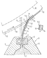
- FIG. 1 is a schematic cross-sectional view of a Applicator according to the invention in the area of a Dosing device shows, described in more detail and explained.
- the invention comprises Commissioned work, which in the present case is a commissioned work for indirect application of a liquid or pasty Application medium 2 on a running material web, in particular made of paper or cardboard, one on one is not shown elongated support element held and by a standby and / or maintenance position in one Operating position movable dosing device D with a as a nozzle, i.e. here more precisely trained as a free jet nozzle Dosing gap 4 between an inlet 6 and a drain-side lip 8 that face each other and from each other are arranged movably, is formed. Of the Dosing device D is used as a carrier surface Applicator roller 10 opposite. The direction of rotation of the roller 10 is indicated by an arrow. From the applicator roller 10 the application medium in a nip, not shown, by which the material web runs through onto the material web transfer.
- a profile bar 12 mounted which a variety of defined, has comb-like or sawtooth-like passage gaps, which together form the passage opening of the metering gap 4 to form.
- One made from a thin, elastic, straight sheet manufactured elongated transfer blade 14 in the area their blade tip assigned to the counter surface 10 has several Through openings 20 or breakthroughs is detachable between the lip 6 on the inlet side and the profile strip 12 clamped, so that the passage gaps enclosing Side of the profile bar 12 flush with a lower section the transfer blade 14 abuts and the lower blade section the transfer blade surface 14.2 a side wall of the Dosing gap 4 forms.
- the standby and / or Maintenance position of the dosing device D has the unloaded transfer blade 14 through in the drawing Starting form shown in dashed lines.
- the Move dosing device D to its operating position or pivoted and the transfer blade 14 on her Blade tip is provided with a bevel on which running application roller 10 pressed.
- the length L of the Transfer blade 14 is here in relation to the applicator roller 10 and depending on the adjustment path required Dosing device D selected so that the transfer blade 14 in the operating position shown by solid lines in an elastically deformed state on the applicator roller 10 rests and assumes a concavely curved shape.
- This Blade 14 style of operation is also called a bent blade style of operation designated.
- the tip of the transfer blade 14 points approximately in the running direction of the applicator roller 10. According to the Detail enlargement Y in the drawing is the Transfer blade 14 on its inlet side, that is Applicator roller 10 contacting blade surface 14.4 with a Ceramic coating 16 provided as wear protection serves.
- the transfer blade 14 sliding over the applicator roller 10 with a certain contact pressure scrapes the air boundary layer 18 carried along by the applicator roller 10.4 with its inlet-side blade surface 14 and at the same time directs that emerging from the metering gap 4 onto its immediately adjacent, outlet-side blade surface 14.2
- Application medium 2 except for the surface of the application roller 10 which is now free of boundary layers. The application of the application medium 2 takes place without excess.
- the pressure ratios built up as a result of the stripping of the air boundary layer 18 in the vicinity of the outlet-side blade tip of the transfer blade 14 are identified in the drawing by the reference symbols p 1 and p 2 , where p 2 is the atmospheric ambient pressure and p 1 is the local pressure which is lower than the atmospheric pressure designated directly on the blade tip on the outlet side.
- the locally lower pressure p 1 causes the application medium 2 to be sucked, so to speak, from the transfer blade surface 14.2 onto the application roller 10, while the atmospheric ambient pressure p 2 simultaneously presses the application medium 2 onto the application roller 10 and thus improves anchoring or adhesion the application roller leads.
- the invention is not limited to the above embodiments, which is only the general explanation of the basic idea serve the invention, limited. Within the scope of protection the application unit according to the invention can rather also others as the configurations described above.
- the Application work can in particular have features that a combination of the individual characteristics of the Represent claims.
- the transfer blade between the inlet side and drain-side lip are also other suitable Types of fastening possible, for example screwing the transfer blade on the inlet lip or the like.
- at least one Embodiment the transfer blade in its unloaded State already have a pre-shaped curvature, which in the operating position at which the transfer blade on the Counter surface rests by the elastic bending of the Transfer blade is further enlarged.
Landscapes
- Engineering & Computer Science (AREA)
- Textile Engineering (AREA)
- Coating Apparatus (AREA)
- Application Of Or Painting With Fluid Materials (AREA)
- Paper (AREA)
- Cleaning Implements For Floors, Carpets, Furniture, Walls, And The Like (AREA)
Abstract
Description
- 2
- Auftragmedium
- 4
- Dosierspalt
- 6
- zulaufseitige Lippe
- 8
- ablaufseitigen Lippe
- 10
- Auftragwalze
- 12
- Profilleiste
- 14
- Transferklinge
- 14.2
- ablaufseitige Fläche von 14
- 14.4
- zulaufseitige Fläche von 14
- 16
- Keramikbeschichtung
- 18
- Luftgrenzschicht
- 20
- Durchgangsöffnungen in 14
- D
- Dosiereinrichtung
- p1
- örtlich niedrigerer Druck
- p2
- Umgebungsdruck
Claims (6)
- Auftragwerk zum direkten oder indirekten Auftragen eines flüssigen oder pastösen Auftragmediums (2) auf eine laufende Materialbahn, insbesondere aus Papier oder Karton, umfassendeine Dosiereinrichtung (D) mit einem als Düse ausgebildeten Dosierspalt (4), der zwischen einer zulaufseitigen (6) und einer ablaufseitigen Lippe (8) gebildet ist, sowieeiner der Düse gegenüberliegenden laufende Gegenfläche (10), auf die das aus dem Dosierspalt (4) austretende Auftragmedium (2) aufzutragen ist,
dadurch gekennnzeichnet, daßsich an den Ausgang des Dosierspalts (4) eine an der zulaufseitigen Lippe (6) angeordnete Transferklinge (14) für das Auftragmedium (2) anschließt, deren Länge (L) in Bezug auf die Gegenfläche (10) so gewählt ist, daß die Transferklinge (14) in der Betriebsposition an der Gegenfläche (10) anliegt und das Auftragmedium (2) entlang der ablaufseitigen Fläche (14.2) der Transferklinge (14) vom Ausgang des Dosierspalts (4) bis auf die Gegenfläche (10) leitet. - Auftragwerk nach Anspruch 1,
dadurch gekennzeichnet, daß
die Transferklinge (14) eine elastisch verformbare Transferklinge ist. - Auftragwerk nach Anspruch 1 oder 2,
dadurch gekennzeichnet, daß
die Transferklinge (14) zumindest an ihrer zulaufseitigen, das heißt die Gegenfläche (10) kontaktierende Klingenfläche (14.4), mit einem Verschleißschutz (16) versehen ist. - Auftragwerk nach Anspruch 3,
dadurch gekennzeichnet, daß
der Verschleißschutz eine Keramikbeschichtung (16) ist. - Auftragwerk nach einem der Ansprüche 1 bis 4,
dadurch gekennzeichnet, daß
die Transferklinge (14) im Bereich ihrer der Gegenfläche (10) zugeordneten Klingenspitze ein oder mehrere Durchgangsöffnungen (20) aufweist. - Auftragwerk nach einem der Ansprüche 1 bis 5,
dadurch gekennzeichnet, daß
dieses wenigstens eine Andrückeinrichtung zum elastischen Verformen und/oder Andrücken der Transferklinge (10) an die laufende Gegenfläche (10) umfaßt.
Applications Claiming Priority (2)
| Application Number | Priority Date | Filing Date | Title |
|---|---|---|---|
| DE19652882 | 1996-12-18 | ||
| DE19652882A DE19652882A1 (de) | 1996-12-18 | 1996-12-18 | Auftragwerk zum direkten oder indirekten Auftragen eines flüssigen oder pastösen Auftragmediums auf eine laufende Materialbahn, insbesondere aus Papier oder Karton |
Publications (2)
| Publication Number | Publication Date |
|---|---|
| EP0849396A1 true EP0849396A1 (de) | 1998-06-24 |
| EP0849396B1 EP0849396B1 (de) | 2004-05-06 |
Family
ID=7815268
Family Applications (1)
| Application Number | Title | Priority Date | Filing Date |
|---|---|---|---|
| EP97119008A Expired - Lifetime EP0849396B1 (de) | 1996-12-18 | 1997-10-31 | Auftragwerk zum direkten oder indirekten Auftragen eines flüssigen oder pastösen Auftragmediums auf eine laufende Materialbahn, insbesondere aus Papier oder Karton |
Country Status (5)
| Country | Link |
|---|---|
| US (1) | US5997646A (de) |
| EP (1) | EP0849396B1 (de) |
| JP (1) | JPH10174919A (de) |
| AT (1) | ATE266124T1 (de) |
| DE (2) | DE19652882A1 (de) |
Cited By (1)
| Publication number | Priority date | Publication date | Assignee | Title |
|---|---|---|---|---|
| US6354870B1 (en) | 1999-08-12 | 2002-03-12 | Matsushita Mobil Communication Development Corp. | Apparatus and method for mounting small electrical connector |
Families Citing this family (4)
| Publication number | Priority date | Publication date | Assignee | Title |
|---|---|---|---|---|
| DE59706505D1 (de) * | 1997-10-24 | 2002-04-04 | Daetwyler Ag | Rakel zum Abrakeln überflüssiger Druckfarbe von der Oberfläche einer Druckform |
| US8545574B2 (en) * | 2003-06-17 | 2013-10-01 | The Procter & Gamble Company | Methods for treating fibrous structures |
| JP2013187236A (ja) * | 2012-03-06 | 2013-09-19 | Tokyo Electron Ltd | 太陽電池製造用のスリットノズル及び薬液塗布装置 |
| US12519543B2 (en) * | 2023-07-21 | 2026-01-06 | Macom Technology Solutions Holdings, Inc. | Signal detection and information conveyance over optical fiber |
Citations (5)
| Publication number | Priority date | Publication date | Assignee | Title |
|---|---|---|---|---|
| US3627564A (en) * | 1970-07-16 | 1971-12-14 | Eastman Kodak Co | Method for coating a continuous web |
| GB2173131A (en) * | 1985-04-01 | 1986-10-08 | Ecc Int Ltd | Trailing blade coating apparatus |
| US5436030A (en) * | 1992-09-11 | 1995-07-25 | Consolidated Papers, Inc. | Apparatus for and method of minimizing skip coating on a paper web |
| DE29520686U1 (de) * | 1995-12-29 | 1996-04-04 | Voith Sulzer Papiermaschinen GmbH, 89522 Heidenheim | Auftragwerk zum direkten oder indirekten Auftragen eines flüssigen oder pastösen Mediums auf eine laufende Materialbahn |
| EP0761877A2 (de) * | 1995-09-06 | 1997-03-12 | Voith Sulzer Papiermaschinen GmbH | Auftragswerk zum direkten oder indirekten Auftragen eines flüssigen oder pastösen Mediums auf eine laufende Materialbahn |
Family Cites Families (8)
| Publication number | Priority date | Publication date | Assignee | Title |
|---|---|---|---|---|
| US3081191A (en) * | 1959-02-18 | 1963-03-12 | Mead Corp | Doctor blade |
| US3230928A (en) * | 1961-02-02 | 1966-01-25 | Oxford Paper Co | Blade coater |
| US4452833A (en) * | 1982-02-08 | 1984-06-05 | Consolidated Papers, Inc. | Paper coating method |
| SE437683B (sv) * | 1982-10-13 | 1985-03-11 | Inventing Ab | Schaber eller rakel - anliggande mot valsen - vid exv tryck-, ferg-, eller kreppning |
| DE4119746A1 (de) * | 1991-06-15 | 1992-12-17 | Voith Gmbh J M | Rakelmesser, insbesondere fuer streicheinrichtungen der papierindustrie |
| US5376177A (en) * | 1993-08-09 | 1994-12-27 | Macmillan Bloedel Limited | Coat weight profiling |
| DE19525458A1 (de) * | 1995-07-14 | 1997-01-16 | Fleissner Maschf Gmbh Co | Vorrichtung zum Aufbringen eines über die Arbeitsbreite gleichmäßig dünnen Flüssigkeitsfilmes auf eine Warenbahn |
| DE29613761U1 (de) * | 1996-08-09 | 1996-12-05 | Lenhardt Maschinenbau GmbH, 75242 Neuhausen | Vorrichtung zum Auftragen eines plastischen Abstandhalters auf eine Glastafel |
-
1996
- 1996-12-18 DE DE19652882A patent/DE19652882A1/de not_active Withdrawn
-
1997
- 1997-10-31 DE DE59711595T patent/DE59711595D1/de not_active Expired - Fee Related
- 1997-10-31 AT AT97119008T patent/ATE266124T1/de not_active IP Right Cessation
- 1997-10-31 EP EP97119008A patent/EP0849396B1/de not_active Expired - Lifetime
- 1997-12-15 US US08/990,445 patent/US5997646A/en not_active Expired - Fee Related
- 1997-12-18 JP JP9364457A patent/JPH10174919A/ja active Pending
Patent Citations (5)
| Publication number | Priority date | Publication date | Assignee | Title |
|---|---|---|---|---|
| US3627564A (en) * | 1970-07-16 | 1971-12-14 | Eastman Kodak Co | Method for coating a continuous web |
| GB2173131A (en) * | 1985-04-01 | 1986-10-08 | Ecc Int Ltd | Trailing blade coating apparatus |
| US5436030A (en) * | 1992-09-11 | 1995-07-25 | Consolidated Papers, Inc. | Apparatus for and method of minimizing skip coating on a paper web |
| EP0761877A2 (de) * | 1995-09-06 | 1997-03-12 | Voith Sulzer Papiermaschinen GmbH | Auftragswerk zum direkten oder indirekten Auftragen eines flüssigen oder pastösen Mediums auf eine laufende Materialbahn |
| DE29520686U1 (de) * | 1995-12-29 | 1996-04-04 | Voith Sulzer Papiermaschinen GmbH, 89522 Heidenheim | Auftragwerk zum direkten oder indirekten Auftragen eines flüssigen oder pastösen Mediums auf eine laufende Materialbahn |
Cited By (1)
| Publication number | Priority date | Publication date | Assignee | Title |
|---|---|---|---|---|
| US6354870B1 (en) | 1999-08-12 | 2002-03-12 | Matsushita Mobil Communication Development Corp. | Apparatus and method for mounting small electrical connector |
Also Published As
| Publication number | Publication date |
|---|---|
| DE59711595D1 (de) | 2004-06-09 |
| JPH10174919A (ja) | 1998-06-30 |
| EP0849396B1 (de) | 2004-05-06 |
| US5997646A (en) | 1999-12-07 |
| ATE266124T1 (de) | 2004-05-15 |
| DE19652882A1 (de) | 1998-06-25 |
Similar Documents
| Publication | Publication Date | Title |
|---|---|---|
| DE2507116A1 (de) | Vorrichtung zum aufbringen eines beschichtungsmaterials und verfahren unter verwendung derselben | |
| DE3338095A1 (de) | Streicheinrichtung | |
| EP0826824B1 (de) | Auftragwerk zum direkten oder indirekten Auftragen eines flüssigen oder pastösen Streichmediums auf eine laufende Materialbahn, insbesondere aus Papier oder Karton | |
| EP0761877A2 (de) | Auftragswerk zum direkten oder indirekten Auftragen eines flüssigen oder pastösen Mediums auf eine laufende Materialbahn | |
| DE4432177A1 (de) | Auftragswerk zum direkten oder indirekten Auftragen eines flüssigen oder pastösen Mediums auf eine laufende Materialbahn | |
| DE4446308C2 (de) | Vorrichtung zum Auftragen eines flüssigen oder pastösen Mediums auf eine laufende Materialbahn | |
| DE4444779B4 (de) | Vorrichtung zum Auftragen eines flüssigen oder pastösen Mediums auf eine laufende Materialbahn, insbesondere aus Papier oder Karton | |
| DE29622365U1 (de) | Auftragswerk zum direkten oder indirekten Auftragen eines flüssigen oder pastösen Mediums auf eine laufende Materialbahn | |
| DE19651739A1 (de) | Auftragwerk zum direkten oder indirekten Auftragen eines flüssigen oder pastösen Streichmediums auf eine laufende Materialbahn, insbesondere aus Papier oder Karton | |
| EP0849396B1 (de) | Auftragwerk zum direkten oder indirekten Auftragen eines flüssigen oder pastösen Auftragmediums auf eine laufende Materialbahn, insbesondere aus Papier oder Karton | |
| DE69511856T2 (de) | Düsenbeschichtungsverfahren und vorrichtung | |
| EP0855464A2 (de) | Vorrichtung und Verfahren zum direkten oder indirekten Auftragen eines flüssigen oder pastösen Mediums auf eine laufende Materialbahn | |
| EP0781885A1 (de) | Auftragswerk zum direkten oder indirekten Auftragen eines flüssigen oder pastösen Mediums auf eine laufende Materialbahn | |
| EP0761878B1 (de) | Vorrichtung zum Auftragen eines flüssigen oder pastösen Mediums auf eine laufende Materialbahn, insbesondere aus Papier oder Karton | |
| DE69405469T2 (de) | Baugruppe zum Laden einer Rakelklinge | |
| DE3612248C2 (de) | Streicheinrichtung | |
| DE3129251C2 (de) | Vorrichtung zur Regulierung des Auftragsgewichtes von Beschichtungen auf in laufender Bahn geführtem Material | |
| EP0109521B1 (de) | Vorrichtung zum Beschichten laufender Materialbahnen | |
| DE19631913A1 (de) | Auftragwerk zum direkten oder indirekten einseitigen oder beidseitigen Auftragen eines flüssigen oder pastösen Mediums auf eine laufende Materialbahn, insbesondere aus Papier oder Karton | |
| DE29624484U1 (de) | Auftragswerk zum direkten oder indirekten Auftragen eines flüssigen oder pastösen Auftragsmedium auf eine laufende Materialbahn, insbesondere aus Papier oder Karton | |
| DE19549085A1 (de) | Auftragwerk zum direkten oder indirekten Auftragen eines flüssigen oder pastösen Mediums auf eine laufende Materialbahn | |
| DE29506731U1 (de) | Auftragswerk zur Beschichtung einer laufenden Warenbahn, insbesondere aus Papier oder Karton | |
| EP0848109A1 (de) | Auftragswerk zum direkten oder indirekten Auftragen eines flüssigen oder pastösen Mediums auf eine laufende Oberfläche | |
| EP1496155B1 (de) | Vorrichtung zum direkten oder indirekten Auftragen von flüssigen bis pastösen Suspensionen auf Papier- oder Kartonbahnen | |
| EP0849395A1 (de) | Auftragwerk zum direkten oder indirekten Auftragen eines flüssigen oder pastösen Streichmediums auf einer laufende Matrialbahn, insbesondere aus Papier onder Karton |
Legal Events
| Date | Code | Title | Description |
|---|---|---|---|
| PUAI | Public reference made under article 153(3) epc to a published international application that has entered the european phase |
Free format text: ORIGINAL CODE: 0009012 |
|
| AK | Designated contracting states |
Kind code of ref document: A1 Designated state(s): AT DE FI IT |
|
| 17P | Request for examination filed |
Effective date: 19981228 |
|
| AKX | Designation fees paid |
Free format text: AT DE FI IT |
|
| RBV | Designated contracting states (corrected) |
Designated state(s): AT DE FI IT |
|
| RAP1 | Party data changed (applicant data changed or rights of an application transferred) |
Owner name: VOITH SULZER PAPIERTECHNIK PATENT GMBH |
|
| RAP1 | Party data changed (applicant data changed or rights of an application transferred) |
Owner name: VOITH PAPER PATENT GMBH |
|
| 17Q | First examination report despatched |
Effective date: 20020927 |
|
| GRAP | Despatch of communication of intention to grant a patent |
Free format text: ORIGINAL CODE: EPIDOSNIGR1 |
|
| GRAS | Grant fee paid |
Free format text: ORIGINAL CODE: EPIDOSNIGR3 |
|
| GRAA | (expected) grant |
Free format text: ORIGINAL CODE: 0009210 |
|
| AK | Designated contracting states |
Kind code of ref document: B1 Designated state(s): AT DE FI IT |
|
| REF | Corresponds to: |
Ref document number: 59711595 Country of ref document: DE Date of ref document: 20040609 Kind code of ref document: P |
|
| PLBE | No opposition filed within time limit |
Free format text: ORIGINAL CODE: 0009261 |
|
| STAA | Information on the status of an ep patent application or granted ep patent |
Free format text: STATUS: NO OPPOSITION FILED WITHIN TIME LIMIT |
|
| 26N | No opposition filed |
Effective date: 20050208 |
|
| PGFP | Annual fee paid to national office [announced via postgrant information from national office to epo] |
Ref country code: DE Payment date: 20071025 Year of fee payment: 11 |
|
| PGFP | Annual fee paid to national office [announced via postgrant information from national office to epo] |
Ref country code: IT Payment date: 20071026 Year of fee payment: 11 Ref country code: FI Payment date: 20071015 Year of fee payment: 11 Ref country code: AT Payment date: 20071015 Year of fee payment: 11 |
|
| PG25 | Lapsed in a contracting state [announced via postgrant information from national office to epo] |
Ref country code: FI Free format text: LAPSE BECAUSE OF NON-PAYMENT OF DUE FEES Effective date: 20081031 |
|
| PG25 | Lapsed in a contracting state [announced via postgrant information from national office to epo] |
Ref country code: IT Free format text: LAPSE BECAUSE OF NON-PAYMENT OF DUE FEES Effective date: 20081031 Ref country code: DE Free format text: LAPSE BECAUSE OF NON-PAYMENT OF DUE FEES Effective date: 20090501 Ref country code: AT Free format text: LAPSE BECAUSE OF NON-PAYMENT OF DUE FEES Effective date: 20081031 |