EP0849506A1 - Federelement zur Wählkrafterzeugung für ein mehrgängiges Zahnräderwechselgetriebe - Google Patents
Federelement zur Wählkrafterzeugung für ein mehrgängiges Zahnräderwechselgetriebe Download PDFInfo
- Publication number
- EP0849506A1 EP0849506A1 EP97119534A EP97119534A EP0849506A1 EP 0849506 A1 EP0849506 A1 EP 0849506A1 EP 97119534 A EP97119534 A EP 97119534A EP 97119534 A EP97119534 A EP 97119534A EP 0849506 A1 EP0849506 A1 EP 0849506A1
- Authority
- EP
- European Patent Office
- Prior art keywords
- spring element
- selector
- spring
- shift
- gear
- Prior art date
- Legal status (The legal status is an assumption and is not a legal conclusion. Google has not performed a legal analysis and makes no representation as to the accuracy of the status listed.)
- Granted
Links
- 230000007935 neutral effect Effects 0.000 claims abstract description 18
- 230000008859 change Effects 0.000 claims abstract description 5
- 230000005540 biological transmission Effects 0.000 claims abstract description 4
- 238000006073 displacement reaction Methods 0.000 claims 1
- 238000000418 atomic force spectrum Methods 0.000 description 8
- 230000008901 benefit Effects 0.000 description 2
- 238000010276 construction Methods 0.000 description 2
- 238000003754 machining Methods 0.000 description 2
- 230000003068 static effect Effects 0.000 description 2
- 230000003993 interaction Effects 0.000 description 1
- 238000000034 method Methods 0.000 description 1
- 230000008569 process Effects 0.000 description 1
Images

Classifications
-
- F—MECHANICAL ENGINEERING; LIGHTING; HEATING; WEAPONS; BLASTING
- F16—ENGINEERING ELEMENTS AND UNITS; GENERAL MEASURES FOR PRODUCING AND MAINTAINING EFFECTIVE FUNCTIONING OF MACHINES OR INSTALLATIONS; THERMAL INSULATION IN GENERAL
- F16H—GEARING
- F16H61/00—Control functions within control units of change-speed- or reversing-gearings for conveying rotary motion ; Control of exclusively fluid gearing, friction gearing, gearings with endless flexible members or other particular types of gearing
- F16H61/24—Providing feel, e.g. to enable selection
-
- F—MECHANICAL ENGINEERING; LIGHTING; HEATING; WEAPONS; BLASTING
- F16—ENGINEERING ELEMENTS AND UNITS; GENERAL MEASURES FOR PRODUCING AND MAINTAINING EFFECTIVE FUNCTIONING OF MACHINES OR INSTALLATIONS; THERMAL INSULATION IN GENERAL
- F16H—GEARING
- F16H59/00—Control inputs to control units of change-speed- or reversing-gearings for conveying rotary motion
- F16H59/02—Selector apparatus
- F16H2059/0295—Selector apparatus with mechanisms to return lever to neutral or datum position, e.g. by return springs
Definitions
- the invention relates to a spring element for dial force generation for a multi-course Gear change transmission according to the preamble of the main claim.
- DE 40 20 160 A1 describes a dial swing arm that at least counteracts the force of a housing-fixed spring element from its neutral to a final selection position is pivotable. If a shift gate is selected using a shift lever, so there is a rotation of the selector and selector shaft, in which the Selector rocker from its middle neutral position against fixed housing Spring elements moved. With the subsequent switching movement the Selector and shift shaft axially shifted.
- DE 40 20 160 A1 describes a linear guide of the Selector and selector shaft in the selector arm that works particularly precisely. Yet is the interaction of the spring element and the swing arm in this version playful. A high static friction of the spring elements causes one high breakaway force of the locking bolts, which have a high hysteresis. Through the large number of components is a superimposition of spring forces and tolerances given. The complex construction necessitates complex housing machining and high demands on the accuracy of the components. So the locking bolts must be ground.
- the invention is therefore based on the object of a play-free for the driver and low-friction haptic feedback through the selection force on the gear lever to provide.
- the spring element consists of at least two against spring force movable rocker arms that are pre-tensioned on the selector arm concern and fix them in their neutral position.
- the rocker arms in the spring element have the advantage that the increased lateral play in the selection direction in the neutral position of the shift lever is avoided. As well the disadvantages in the course of the electoral process are avoided.
- the spring element with Rocker arms have less static friction and less hysteresis.
- the spring element consists of three rocker arms and a spring that work together so that starting from the neutral position of the selector and selector shaft in a shift gate three more Switching lanes can each be selected with at least one increase in the election force.
- the spring element is in the Gearbox attached.
- the spring element is pre-assembled in a housing or on a base plate, a modular design is also possible with simple machining of the gear housing.
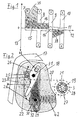
- FIG. 1 a selection force curve is shown qualitatively, that with a spring element is achieved according to the invention.
- a shift pattern with four shift gates 7, 8, 9, 10 and a dialing lane 11 is on an abscissa 12 of the dialing path above Dial force plotted on an ordinate 13.
- the end positions of the shift lever 14 in the Shift lanes 7, 8, 9, 10 after engaging the respective gears are through the Numbers 1 to 6 and the letter R are shown.
- the numbers correspond the gear engaged and R means reverse gear engaged.
- the shaded Area 15 with its limiting curve 16 corresponds to the size of the dialing force.
- the selection force changes when leaving a shift gate 7, 8, 9, 10 changed in one jump.
- the dial force maintains a constant value while it when moving the shift lever 14 from the shift gate 9 into the shift gate 10 for the fifth and sixth gear after a sudden increase drops steadily.
- moving the shift lever 14 from the shift gate 8 for the first and second gear in Weggasse 7 for the reverse gear increases the selection force after a sudden increase, then briefly remains constant, before reaching the Weggasse 7 in turn decrease steadily.
- Such a course of the selection force is achieved with the spring element from FIG. 2.
- gear housing 17 that is in one Housing 18 pre-assembled spring element attached by means not shown.
- a central selector and selector shaft 19 is guided in the gear housing 17.
- This selector and switching shaft 19 is not selected during the selection in this figure shown shift gate 7, 8, 9, 10 by means of the also not shown in this figure Shift lever 14 rotated and the subsequent switching one within this shift gate 7, 8, 9, 10 lying gear shifted axially.
- the Selector and selector shaft 19 takes up shift fingers, not shown, depending on Training of the circuit in associated with shift forks not shown Selector rails selectively intervene or directly on not drawn Selector arms attacking shift sleeves selectively perform gear shifting.
- gear housing 17 is also formed as a one-armed lever Selector rocker 20 shown in dashed lines rotatably mounted by means of its hub 21.
- This selector rocker 20 receives one at its radially projecting end a dashed bolt 22 mounted, dashed roller 23, which, against rocker arms 24, 25, 26 located in their swivel range Spring element is movable.
- the selector and switching shaft 19 is axially displaceable in the hub 21 the swing arm 20 stored.
- swing arm 20 and dial and Switch shaft 19 in the circumferential direction by the balls 27 in a form-fitting manner connected so that during a selection movement of the shift lever, not shown 14 the selector arm 20 is rotated with the selector and switching shaft 19 while it maintains its position during a switching movement of the selector and switching shaft 19.
- the rocker arms 24, 25, 26 are used together with a spring 42 for generation of a selection force curve according to FIG. 1.
- the rocker arm 24 is for generation the selection force for the reverse gear in the housing 18 of the spring element rotatable about a hinge point 43 and supported on the spring 42.
- the rocker arm 25 for generating the selection force for the shift gate of the fifth and sixth gear is via a further hinge point 29 on the housing 18th of the spring element rotatably and slidably mounted in the longitudinal direction and additionally rotatable with the rocker arm 24 via an articulated connection 30 connected.
- the rocker arm 26 for generating the selector force for the shift gate the first and second gear can in turn be rotated and moved in the longitudinal direction mounted on the hinge point 43 on the housing 18 of the spring element and rotatable via a further articulation 31 with the rocker arm 25 connected.
- the rocker arms 24, 25, 26 are designed such that they have active surfaces 32, 33, 34 hold the roller 23 of the selector rocker 20 in the manner of pliers and hold it in without play determine their neutral position of the shift gate for the third and fourth gear.
- the contours of the active surfaces 32, 33, 34 shape the continuous course the dial force curve, while the jumps in the dial force curve result from that at least one other rocker arm 24, 25, 26 with the roller 23 of the Dial rocker 20 comes into contact.
- roller 23 has the width of all rocker arms 24, 25, 26 together.
- Figure 3 shows the selector rocker 20 in contact with the rocker arm 24 when inserting of reverse gear.
- the contour of the active surface 32 causes the change in slope the curve for the selection force curve 35, shown in FIG. 1.
- the arrow 36 indicates the direction of movement of the selector arm 20 and the arrow 37 the direction of movement the rocker arm 24.
- Figure 4 shows with arrow 38 the direction of movement of the dial 20 at Select the shift gate 10 for the fifth and sixth gear.
- the roller 23 of the selector arm 20 on the active surface 33 of the rocker arm 25, whose contour causes the falling course 39 of the dialing force curve from FIG. 1.
- the rocker arm 25 moves in the direction of the arrow 40.
- Figure 5 shows the selector rocker 20 in its neutral position, the shift gate 9 for the third and fourth gear.
- the dial 20 is to be turned in the direction of arrow 41.
- the roller 23 of the selector rocker 20 rolls on the active surface 34 of the rocker arm 26 from, to generate the selection force for the shift gate 8 of the first and second course.
- the rocker arm 26 moves in the direction of the arrow 44.
- the roller 23 is like the pliers Active surfaces 33, 34 of the rocker arms 25, 26 bordered, which is a play-free definition the dial rocker 20 causes.
Landscapes
- Engineering & Computer Science (AREA)
- General Engineering & Computer Science (AREA)
- Mechanical Engineering (AREA)
- Gear-Shifting Mechanisms (AREA)
Abstract
Description
- Figur 1
- den mit einem Federelement gemäß der Erfindung erzielten qualitativen Wählkraftverlauf,
- Figur 2
- das Federelement mit Wählschwinge, eingebaut im Getriebegehäuse, in einem Teilschnitt des Getriebes,
- Figur 3
- einen Teil des Federelements mit Wählschwinge, nötig zum Erzeugen der Wählkraft für den Rückwärtsgang,
- Figur 4
- einen Teil des Federelements mit Wählschwinge, nötig zum Erzeugen der Wählkraft für die Schaltgasse des fünften und sechsten Ganges,
- Figur 5
- das Federelement mit Wählschwinge in Neutralstellung.
Claims (4)
- Federelement für eine Schalteinrichtung, für ein mehrgängiges Zahnräderwechselgetriebe eines Kraftfahrzeugs, mit einer zentralen Wähl- und Schaltwelle (19), die in einem Getriebegehäuse (17) verdrehbar und axial verschiebbar gelagert ist, wobei durch deren Verdrehung jeweils eine in einer Schaltgasse (7, 8, 9, 10) zu betätigende Schaltkupplung anwählbar und durch deren anschließende axiale Verschiebung Gangstufen (1,2,3,4,5,6,R) schaltbar sind, mit einer als Hebel ausgebildeten Wählschwinge (20), die drehfest und axial verschiebbar bezüglich der Wähl- und Schaltwelle (19) geführt ist und die gegen die Kraft des Federelementes aus ihrer Neutral- in mindestens eine Wählendstellung verschwenkbar ist, dadurch gekennzeichnet, daß das Federelement aus mindestens zwei, gegen die Kraft mindestens einer Feder (42) beweglichen, Schlepphebeln (24, 25, 26) besteht, die unter Vorspannung an der Wählschwinge (20) anliegen und diese in ihrer Neutralstellung festlegen.
- Federelement nach Anspruch 1, dadurch gekennzeichnet, daß es aus drei Schlepphebeln (24, 25, 26) und einer Feder (42) besteht, die so zusammenwirken, daß ausgehend von der Neutralstellung der Wähl- und Schaltwelle (19) in einer Schaltgasse (9) drei weitere Schaltgassen (7, 8, 10) jeweils mit mindestens je einer Wählkrafterhöhung anwählbar sind.
- Federelement nach Anspruch 1 oder 2, dadurch gekennzeichnet, daß es im Getriebegehäuse (17) angebracht ist.
- Federelement nach Anspruch 3, dadurch gekennzeichnet, daß es in einem Gehäuse (18) oder auf einer Grundplatte vormontiert ist.
Applications Claiming Priority (2)
| Application Number | Priority Date | Filing Date | Title |
|---|---|---|---|
| DE19653171A DE19653171A1 (de) | 1996-12-19 | 1996-12-19 | Federelement zur Wählkrafterzeugung für ein mehrgängiges Zahnräderwechselgetriebe |
| DE19653171 | 1996-12-19 |
Publications (2)
| Publication Number | Publication Date |
|---|---|
| EP0849506A1 true EP0849506A1 (de) | 1998-06-24 |
| EP0849506B1 EP0849506B1 (de) | 2002-07-03 |
Family
ID=7815455
Family Applications (1)
| Application Number | Title | Priority Date | Filing Date |
|---|---|---|---|
| EP97119534A Expired - Lifetime EP0849506B1 (de) | 1996-12-19 | 1997-11-07 | Schalteinrichtung mit Federelement zur Wählkrafterzeugung für ein mehrgängiges Zahnräderwechselgetriebe |
Country Status (2)
| Country | Link |
|---|---|
| EP (1) | EP0849506B1 (de) |
| DE (2) | DE19653171A1 (de) |
Cited By (10)
| Publication number | Priority date | Publication date | Assignee | Title |
|---|---|---|---|---|
| FR2817316A1 (fr) | 2000-11-30 | 2002-05-31 | Schaeffler Waelzlager Ohg | Installation de selection et de commutation d'une boite de vitesses pour selectionner entre au moins deux chemins de commutation |
| WO2003038316A1 (de) * | 2001-11-02 | 2003-05-08 | Ina-Schaeffler Kg | Vorrichtung für das erzeugen von schaltkräften |
| EP1333199A2 (de) | 2002-01-31 | 2003-08-06 | INA-Schaeffler KG | Vorrichtung zum Erhöhen einer Wählkraft |
| DE10204282A1 (de) * | 2002-02-02 | 2003-08-07 | Ina Schaeffler Kg | Lageranordnung zur schwenkbaren Lagerung eines Schalthebels |
| EP1342940A2 (de) | 2002-03-06 | 2003-09-10 | INA-Schaeffler KG | Vorrichtung zum Erzeugen einer Gegenkraft an einer Schaltwelle |
| EP1342941A2 (de) | 2002-03-06 | 2003-09-10 | INA-Schaeffler KG | Vorrichtung zum Erzeugen einer Gegenkraft an einer Schaltwelle |
| EP1333196A3 (de) * | 2002-01-31 | 2005-10-26 | INA-Schaeffler KG | Lageranordnung zur schwenkbaren Lagerung eines Schalthebels |
| WO2008052922A1 (de) * | 2006-11-02 | 2008-05-08 | Schaeffler Kg | Vorrichtung zum verändern von betätigungskräften an einem schaltorgan |
| EP1965099A2 (de) | 2007-03-01 | 2008-09-03 | Dr. Ing. h.c. F. Porsche Aktiengesellschaft | Schalteinrichtung mit Federelement zur Wählkrafterzeugung für ein mehrgängiges Zahnräderwechselgetriebe |
| FR3037161A1 (fr) * | 2015-06-08 | 2016-12-09 | Peugeot Citroen Automobiles Sa | Dispositif de commande de vitesse d'une boite de vitesses manuelle de vehicule automobile |
Families Citing this family (9)
| Publication number | Priority date | Publication date | Assignee | Title |
|---|---|---|---|---|
| DE10000338A1 (de) * | 2000-01-07 | 2001-07-12 | Volkswagen Ag | Vorrichtung zur Ermittlung des bei einem Kraftfahrzeug eingelegten Ganges |
| DE10016364A1 (de) * | 2000-04-04 | 2001-10-11 | Zahnradfabrik Friedrichshafen | Wähl-und Schaltmodul für ein Handschaltgetriebe |
| DE10229320A1 (de) * | 2002-06-29 | 2004-01-15 | Zf Friedrichshafen Ag | Schalteinrichtung |
| DE102005023926A1 (de) | 2005-05-24 | 2006-11-30 | Leopold Kostal Gmbh & Co. Kg | Elektrische Schalteinrichtung für ein Kraftfahrzeug |
| DE102007035304A1 (de) | 2007-07-27 | 2009-01-29 | Dr. Ing. H.C. F. Porsche Aktiengesellschaft | Schalteinrichtung für ein mehrgängiges Zahnräderwechselgetriebe eines Kraftfahrzeuges |
| DE102009007814A1 (de) | 2009-02-06 | 2010-08-12 | Dr. Ing. H.C. F. Porsche Aktiengesellschaft | Schaltvorrichtung für ein mehrstufiges Handschaltgetriebe |
| DE102012210789A1 (de) | 2012-06-26 | 2014-01-02 | Zf Friedrichshafen Ag | Schaltvorrichtung eines Handschaltgetriebes für Kraftfahrzeuge |
| DE202015006951U1 (de) * | 2015-10-06 | 2017-01-10 | Gm Global Technology Operations, Llc | Schaltgetriebe-Betätigungsvorrichtung |
| DE102018004360B3 (de) * | 2018-06-01 | 2019-10-31 | Psa Automobiles Sa | Externe Schaltbetätigung mit asymmetrischer Wählfedercharakteristik |
Citations (5)
| Publication number | Priority date | Publication date | Assignee | Title |
|---|---|---|---|---|
| DE1500367A1 (de) * | 1951-01-28 | 1969-06-12 | Daimler Benz Ag | Schaltsperrvorrichtung fuer ein Wechselgetriebe,insbesondere von Kraftfahrzeugen |
| GB2037916A (en) * | 1978-12-07 | 1980-07-16 | Saab Scania Ab | Device in a gear selection mechanism for a manual vehicle transmission |
| WO1983000398A1 (en) * | 1981-07-23 | 1983-02-03 | AKERSTRÖM, Ake | A device at a manually operated to an original position automatically returning control lever |
| US5144854A (en) * | 1991-03-08 | 1992-09-08 | Chrysler Corporation | Transmission shift control reverse inhibitor apparatus |
| DE19520209A1 (de) * | 1994-06-02 | 1995-12-07 | Aisin A I Co | Schaltmechanismus für ein handgeschaltetes Getriebe |
Family Cites Families (2)
| Publication number | Priority date | Publication date | Assignee | Title |
|---|---|---|---|---|
| DE3430958A1 (de) * | 1984-08-20 | 1986-02-27 | Helmut Prof. Dr. 4020 Mettmann Käufer | Feder mit zusaetzlicher funktion als multifunktionales teil aus kunststoff |
| US5140866A (en) * | 1989-06-29 | 1992-08-25 | Zahnradfabrik Friedrichshafen Ag | Gearshift device for a multiple-gear gear change box in a motor |
-
1996
- 1996-12-19 DE DE19653171A patent/DE19653171A1/de not_active Withdrawn
-
1997
- 1997-11-07 DE DE59707644T patent/DE59707644D1/de not_active Expired - Fee Related
- 1997-11-07 EP EP97119534A patent/EP0849506B1/de not_active Expired - Lifetime
Patent Citations (5)
| Publication number | Priority date | Publication date | Assignee | Title |
|---|---|---|---|---|
| DE1500367A1 (de) * | 1951-01-28 | 1969-06-12 | Daimler Benz Ag | Schaltsperrvorrichtung fuer ein Wechselgetriebe,insbesondere von Kraftfahrzeugen |
| GB2037916A (en) * | 1978-12-07 | 1980-07-16 | Saab Scania Ab | Device in a gear selection mechanism for a manual vehicle transmission |
| WO1983000398A1 (en) * | 1981-07-23 | 1983-02-03 | AKERSTRÖM, Ake | A device at a manually operated to an original position automatically returning control lever |
| US5144854A (en) * | 1991-03-08 | 1992-09-08 | Chrysler Corporation | Transmission shift control reverse inhibitor apparatus |
| DE19520209A1 (de) * | 1994-06-02 | 1995-12-07 | Aisin A I Co | Schaltmechanismus für ein handgeschaltetes Getriebe |
Cited By (19)
| Publication number | Priority date | Publication date | Assignee | Title |
|---|---|---|---|---|
| DE10059376A1 (de) * | 2000-11-30 | 2002-07-11 | Ina Schaeffler Kg | Wähl- und Schalteinrichtung eines Getriebes zum Wählen zwischen wenigstens zwei Schaltgassen |
| FR2817316A1 (fr) | 2000-11-30 | 2002-05-31 | Schaeffler Waelzlager Ohg | Installation de selection et de commutation d'une boite de vitesses pour selectionner entre au moins deux chemins de commutation |
| DE10059376B4 (de) * | 2000-11-30 | 2014-09-04 | Schaeffler Technologies Gmbh & Co. Kg | Wähl- und Schalteinrichtung eines Getriebes zum Wählen zwischen wenigstens zwei Schaltgassen |
| WO2003038316A1 (de) * | 2001-11-02 | 2003-05-08 | Ina-Schaeffler Kg | Vorrichtung für das erzeugen von schaltkräften |
| EP1333199A3 (de) * | 2002-01-31 | 2005-10-26 | INA-Schaeffler KG | Vorrichtung zum Erhöhen einer Wählkraft |
| EP1333199A2 (de) | 2002-01-31 | 2003-08-06 | INA-Schaeffler KG | Vorrichtung zum Erhöhen einer Wählkraft |
| EP1333196A3 (de) * | 2002-01-31 | 2005-10-26 | INA-Schaeffler KG | Lageranordnung zur schwenkbaren Lagerung eines Schalthebels |
| DE10204282A1 (de) * | 2002-02-02 | 2003-08-07 | Ina Schaeffler Kg | Lageranordnung zur schwenkbaren Lagerung eines Schalthebels |
| DE10209730A1 (de) * | 2002-03-06 | 2003-09-18 | Ina Schaeffler Kg | Vorrichtung zum Erzeugen einer Gegenkraft an einer Schaltwelle |
| EP1342941A3 (de) * | 2002-03-06 | 2005-04-06 | INA-Schaeffler KG | Vorrichtung zum Erzeugen einer Gegenkraft an einer Schaltwelle |
| EP1342940A3 (de) * | 2002-03-06 | 2005-04-13 | INA-Schaeffler KG | Vorrichtung zum Erzeugen einer Gegenkraft an einer Schaltwelle |
| DE10209729A1 (de) * | 2002-03-06 | 2003-09-18 | Ina Schaeffler Kg | Vorrichtung zum Erzeugen einer Gegenkraft an einer Schaltwelle |
| EP1342941A2 (de) | 2002-03-06 | 2003-09-10 | INA-Schaeffler KG | Vorrichtung zum Erzeugen einer Gegenkraft an einer Schaltwelle |
| EP1342940A2 (de) | 2002-03-06 | 2003-09-10 | INA-Schaeffler KG | Vorrichtung zum Erzeugen einer Gegenkraft an einer Schaltwelle |
| WO2008052922A1 (de) * | 2006-11-02 | 2008-05-08 | Schaeffler Kg | Vorrichtung zum verändern von betätigungskräften an einem schaltorgan |
| EP1965099A2 (de) | 2007-03-01 | 2008-09-03 | Dr. Ing. h.c. F. Porsche Aktiengesellschaft | Schalteinrichtung mit Federelement zur Wählkrafterzeugung für ein mehrgängiges Zahnräderwechselgetriebe |
| DE102007009988A1 (de) | 2007-03-01 | 2008-09-04 | Dr. Ing. H.C. F. Porsche Aktiengesellschaft | Schalteinrichtung mit Federelement zur Wählkrafterzeugung für ein mehrgängiges Zahnräderwechselgetriebe |
| EP1965099A3 (de) * | 2007-03-01 | 2010-10-20 | Dr. Ing. h.c. F. Porsche AG | Schalteinrichtung mit Federelement zur Wählkrafterzeugung für ein mehrgängiges Zahnräderwechselgetriebe |
| FR3037161A1 (fr) * | 2015-06-08 | 2016-12-09 | Peugeot Citroen Automobiles Sa | Dispositif de commande de vitesse d'une boite de vitesses manuelle de vehicule automobile |
Also Published As
| Publication number | Publication date |
|---|---|
| EP0849506B1 (de) | 2002-07-03 |
| DE19653171A1 (de) | 1998-06-25 |
| DE59707644D1 (de) | 2002-08-08 |
Similar Documents
| Publication | Publication Date | Title |
|---|---|---|
| EP0849506B1 (de) | Schalteinrichtung mit Federelement zur Wählkrafterzeugung für ein mehrgängiges Zahnräderwechselgetriebe | |
| EP0731885B1 (de) | Schaltvorrichtung | |
| EP0903518B1 (de) | Schaltvorrichtung für ein Wechselgetriebe von Kraftfahrzeugen | |
| DE3150885C2 (de) | ||
| EP0800025B1 (de) | Stelleinrichtung zur Automatisierung von Handschaltgetrieben von Kraftfahrzeugen | |
| DE19842532A1 (de) | Schaltvorrichtung | |
| EP0530466B1 (de) | Gangschaltung eines Kraftfahrzeuggetriebes | |
| DE3016909C2 (de) | Schaltvorrichtung für ein mehrgängiges Zahnräder-Wechselgetriebe | |
| DE69402101T2 (de) | Gangschaltungseinrichtung für ein automatisches Kraftfahrzeuggetriebe | |
| DE19637254A1 (de) | Wählvorrichtung für ein Automatikgetriebe eines Kraftfahrzeuges | |
| EP0999384B1 (de) | Schaltvorrichtung für Wechselgetriebe von Kraftfahrzeugen | |
| DE19520209B4 (de) | Schaltmechanismus für ein manuell schaltbares Getriebe | |
| EP0825364A2 (de) | Wähleinrichtung für ein Automatikgetriebe eines Kraftfahrzeugs | |
| DE2341199A1 (de) | Schalteinrichtung fuer mechanische wechselgetriebe von kraftfahrzeugen | |
| DE3742600C2 (de) | ||
| EP0771975A1 (de) | Schaltvorrichtung für ein Schaltgetriebe | |
| EP0928725B1 (de) | Parksperreinrichtung für ein Kraftfahrzeug mit Stufenwechselgetriebe | |
| EP0770802A2 (de) | Schalteinrichtung für Kraftfahrzeug-Wechselgetriebe mit Abbremsung der Eingangswelle beim Einschalten des Rückwärtsganges | |
| DE2621714B1 (de) | Schalteinrichtung fuer ein kraftfahrzeug-wechselgetriebe | |
| DE102018206392B4 (de) | Schalteinrichtung zur durchführung von gangwechseln in einem fahrzeuggetriebe | |
| EP0790443A2 (de) | Schaltvorrichtung ohne Leergangbewegung während einer Einrückbewegung des Rückwärtsganges | |
| DE3842818C1 (en) | Selector device for a motor-vehicle gearbox | |
| DE60001023T2 (de) | Steuervorrichtung für den Gangwechsel eines mechanischen Getriebegehäuses eines Kraftfahrzeugs | |
| DE60006457T2 (de) | Getriebe kompakter Bauart mit Schwenkfüssen zur Betätigung von Schaltgabeln | |
| EP1310707B1 (de) | Schaltvorrichtung für ein Wechselgetriebe und Verfahren zur Bewegung und Führung von Schaltgabeln in einem Wechselgetriebe |
Legal Events
| Date | Code | Title | Description |
|---|---|---|---|
| PUAI | Public reference made under article 153(3) epc to a published international application that has entered the european phase |
Free format text: ORIGINAL CODE: 0009012 |
|
| 17P | Request for examination filed |
Effective date: 19980416 |
|
| AK | Designated contracting states |
Kind code of ref document: A1 Designated state(s): DE FR GB IT |
|
| AX | Request for extension of the european patent |
Free format text: AL;LT;LV;MK;RO;SI |
|
| AKX | Designation fees paid |
Free format text: DE FR GB IT |
|
| RBV | Designated contracting states (corrected) |
Designated state(s): DE FR GB IT |
|
| 17Q | First examination report despatched |
Effective date: 20010905 |
|
| GRAG | Despatch of communication of intention to grant |
Free format text: ORIGINAL CODE: EPIDOS AGRA |
|
| RTI1 | Title (correction) |
Free format text: SELECTOR DEVICE WITH SPRING-BIASING ARRANGEMENT FOR PROVIDING SELECTION FEEL IN A MULTI-RATIO GEARBOX |
|
| GRAG | Despatch of communication of intention to grant |
Free format text: ORIGINAL CODE: EPIDOS AGRA |
|
| GRAH | Despatch of communication of intention to grant a patent |
Free format text: ORIGINAL CODE: EPIDOS IGRA |
|
| GRAH | Despatch of communication of intention to grant a patent |
Free format text: ORIGINAL CODE: EPIDOS IGRA |
|
| GRAA | (expected) grant |
Free format text: ORIGINAL CODE: 0009210 |
|
| AK | Designated contracting states |
Kind code of ref document: B1 Designated state(s): DE FR GB IT |
|
| GBT | Gb: translation of ep patent filed (gb section 77(6)(a)/1977) |
Effective date: 20020703 |
|
| REF | Corresponds to: |
Ref document number: 59707644 Country of ref document: DE Date of ref document: 20020808 |
|
| ET | Fr: translation filed | ||
| PLBE | No opposition filed within time limit |
Free format text: ORIGINAL CODE: 0009261 |
|
| STAA | Information on the status of an ep patent application or granted ep patent |
Free format text: STATUS: NO OPPOSITION FILED WITHIN TIME LIMIT |
|
| 26N | No opposition filed |
Effective date: 20030404 |
|
| PGFP | Annual fee paid to national office [announced via postgrant information from national office to epo] |
Ref country code: IT Payment date: 20081127 Year of fee payment: 12 |
|
| PGFP | Annual fee paid to national office [announced via postgrant information from national office to epo] |
Ref country code: FR Payment date: 20081128 Year of fee payment: 12 |
|
| PGFP | Annual fee paid to national office [announced via postgrant information from national office to epo] |
Ref country code: DE Payment date: 20081211 Year of fee payment: 12 |
|
| PGFP | Annual fee paid to national office [announced via postgrant information from national office to epo] |
Ref country code: GB Payment date: 20081127 Year of fee payment: 12 |
|
| GBPC | Gb: european patent ceased through non-payment of renewal fee |
Effective date: 20091107 |
|
| REG | Reference to a national code |
Ref country code: FR Ref legal event code: ST Effective date: 20100730 |
|
| PG25 | Lapsed in a contracting state [announced via postgrant information from national office to epo] |
Ref country code: FR Free format text: LAPSE BECAUSE OF NON-PAYMENT OF DUE FEES Effective date: 20091130 |
|
| PG25 | Lapsed in a contracting state [announced via postgrant information from national office to epo] |
Ref country code: DE Free format text: LAPSE BECAUSE OF NON-PAYMENT OF DUE FEES Effective date: 20100601 |
|
| PG25 | Lapsed in a contracting state [announced via postgrant information from national office to epo] |
Ref country code: GB Free format text: LAPSE BECAUSE OF NON-PAYMENT OF DUE FEES Effective date: 20091107 |
|
| PG25 | Lapsed in a contracting state [announced via postgrant information from national office to epo] |
Ref country code: IT Free format text: LAPSE BECAUSE OF NON-PAYMENT OF DUE FEES Effective date: 20091107 |