EP0849507A2 - Tringlerie de changement de vitesses pour la transmission des efforts de selection - Google Patents
Tringlerie de changement de vitesses pour la transmission des efforts de selection Download PDFInfo
- Publication number
- EP0849507A2 EP0849507A2 EP97122009A EP97122009A EP0849507A2 EP 0849507 A2 EP0849507 A2 EP 0849507A2 EP 97122009 A EP97122009 A EP 97122009A EP 97122009 A EP97122009 A EP 97122009A EP 0849507 A2 EP0849507 A2 EP 0849507A2
- Authority
- EP
- European Patent Office
- Prior art keywords
- lever
- switching device
- neutral position
- axis
- transmission
- Prior art date
- Legal status (The legal status is an assumption and is not a legal conclusion. Google has not performed a legal analysis and makes no representation as to the accuracy of the status listed.)
- Granted
Links
Images


Classifications
-
- F—MECHANICAL ENGINEERING; LIGHTING; HEATING; WEAPONS; BLASTING
- F16—ENGINEERING ELEMENTS AND UNITS; GENERAL MEASURES FOR PRODUCING AND MAINTAINING EFFECTIVE FUNCTIONING OF MACHINES OR INSTALLATIONS; THERMAL INSULATION IN GENERAL
- F16H—GEARING
- F16H35/00—Gearings or mechanisms with other special functional features
- F16H35/14—Mechanisms with only two stable positions, e.g. acting at definite angular positions
-
- F—MECHANICAL ENGINEERING; LIGHTING; HEATING; WEAPONS; BLASTING
- F16—ENGINEERING ELEMENTS AND UNITS; GENERAL MEASURES FOR PRODUCING AND MAINTAINING EFFECTIVE FUNCTIONING OF MACHINES OR INSTALLATIONS; THERMAL INSULATION IN GENERAL
- F16H—GEARING
- F16H61/00—Control functions within control units of change-speed- or reversing-gearings for conveying rotary motion ; Control of exclusively fluid gearing, friction gearing, gearings with endless flexible members or other particular types of gearing
- F16H61/24—Providing feel, e.g. to enable selection
-
- F—MECHANICAL ENGINEERING; LIGHTING; HEATING; WEAPONS; BLASTING
- F16—ENGINEERING ELEMENTS AND UNITS; GENERAL MEASURES FOR PRODUCING AND MAINTAINING EFFECTIVE FUNCTIONING OF MACHINES OR INSTALLATIONS; THERMAL INSULATION IN GENERAL
- F16H—GEARING
- F16H63/00—Control outputs from the control unit to change-speed- or reversing-gearings for conveying rotary motion or to other devices than the final output mechanism
- F16H63/02—Final output mechanisms therefor; Actuating means for the final output mechanisms
- F16H63/30—Constructional features of the final output mechanisms
- F16H63/38—Detents
-
- F—MECHANICAL ENGINEERING; LIGHTING; HEATING; WEAPONS; BLASTING
- F16—ENGINEERING ELEMENTS AND UNITS; GENERAL MEASURES FOR PRODUCING AND MAINTAINING EFFECTIVE FUNCTIONING OF MACHINES OR INSTALLATIONS; THERMAL INSULATION IN GENERAL
- F16H—GEARING
- F16H59/00—Control inputs to control units of change-speed- or reversing-gearings for conveying rotary motion
- F16H59/02—Selector apparatus
- F16H59/04—Ratio selector apparatus
- F16H59/042—Ratio selector apparatus comprising a final actuating mechanism
Definitions
- the invention relates to a switching device for transmission of switching forces for a between a neutral position and at least one non-neutral position switchable transmission, especially for a vehicle manual transmission.
- gearboxes which are operated by a gear lever between a neutral position and a gear shift position or between different transmission ratios are switchable, is not always one when switching correct shift position of the gearbox reached, but unintentionally set an intermediate position that neither the Neutral position still a clear gear of the transmission assigned.
- a device is desirable to provide an automatic detection more accurate Positions enabled. These exact positions should be also set automatically when on the Gear shift lever no locking positions are provided.
- EP-A-0 137 826 describes a gear shift device in which is a gearshift lever with a flexible cable Transmission is connected.
- the gear shift lever is at two mutually perpendicular axes pivotable.
- To the Gear shift lever reliable with respect to a swivel direction in a desired middle neutral position or one to maintain the deflected gear engagement position Swivel direction influenced by a coil spring.
- the core the coil spring is supported on a bolt.
- the after protruding legs of the coil spring engage Elongated hole of a swiveling attached to the gear shift lever Lever and push it into a middle position, the corresponds to the neutral position.
- the elongated hole contains Locking positions that hold the gear shift lever in should serve a gear engagement position.
- the object underlying the invention is seen in a switching device for the transmission of switching forces for one between a neutral position and at least one
- a switching device for the transmission of switching forces for one between a neutral position and at least one
- it is intended to find the neutral position safely or a non-neutral position and a safe hold in these positions may be possible.
- It is supposed to be a restoring force be created, which a reset of the switching device in the neutral position is guaranteed provided the deflection position for a non-neutral position has not yet been achieved.
- the switching device should not have high requirements Establish manufacturing tolerances and wear precautions and be easy and inexpensive to manufacture and assemble. she should also be used for power transmission Bowden cables may be suitable.
- the switching device contains a first one Lever, which is used with a gear change Gear shift lever is connected and through this a first stationary axis is pivotable, and a second Lever, the one parallel to the first axis stationary axis is pivotally mounted.
- a switching element of the transmission is in with the first or the second lever Connection to be able to switch gears.
- the gear shift lever is for example a manually operable Shift stick, and the switching element can be z. B. around a rotatable selector shaft or sliding selector rod act of the transmission.
- Each of the two levers has at least one leg, the are connected by a joint.
- the articulation point allows shifting on the one hand and on the other a rotation of the two legs relative to each other, so that a buckling of the legs from their neutral position against the Force of the spring element is possible. It is also at least a locking position is provided, which is a non-neutral position corresponds to the gear in which the bent legs persist despite the action of the spring element.
- the angle of rotation can be increased without the Increase tolerance angle, d. H. the input rotation angle of the first lever is in an enlarged angle of rotation of the second lever translated.
- the invention Switching device enables a safe location of the Neutral position or a non-neutral position and a reliable hold in this position. It will be one Restoring force generates a reset of the Switching device guaranteed in the neutral position, if the deflection position for a non-neutral position is not yet was achieved.
- the manufacturing tolerances can be generous be dimensioned as they are not essential to the Affect the functionality of the switching device. Also Signs of wear and incorrect settings have only one little influence on the functioning of the switching device, which is particularly suitable for a power transmission Bowden cables are suitable.
- the interpretation is preferably such that when adjusting the Gear shift lever the force of the spring element based on the neutral position increases rapidly. It is advisable when the spring force of the spring element is in the neutral position is low or zero. This allows one to be removed find the gear shift lever lying in its neutral alley can not and not by the spring element in another its neutral alley is pushed.
- a tension spring as a spring element, for example a helical tension spring with bent Ends or eyelets at their ends.
- An end to Tension spring can attack the second leg during that the other end is attached to a hinge that is in a Alignment line with the first and second axes.
- the one formed on the second lever Articulation point of the spring element with respect to the second axis on the side of the lever opposite the joint (Fig. 1).
- the first axis lies, the second Axis and the articulation point of the spring element in one Escape line in a row.
- the switching device can be designed so that the both levers in the non-neutral position make an angle of 90 ° or take something over it, so that in this position the Spring element does not apply a force component that the two Lever pushes into its neutral position.
- a rest position that corresponds to the non-neutral position, but can be realize in a simple manner that the longitudinal slot in the area of its end facing the first lever has lateral bulge, in which one with the first lever connected pin-shaped element engages and latches, if the levers are in the non-neutral position.
- cone-shaped element as a spherical bearing on a shaft Train role.
- the first lever is preferably rotatably mounted Shaft non-rotatably connected, whose axis of rotation is the first axis and which rotatably carries another lever on which the Gear shift lever attacks directly or indirectly.
- Another lever can be, for example, a pull-push Bowden cable attack the power transmission one by hand adjustable gear shift lever is used.
- the Axis of rotation to be connected to the switching element of the transmission.
- a stable construction results when the first lever in essentially consists of two parallel legs, between its free ends there is a peg-shaped element extends parallel to the first axis, the peg-shaped Element in a substantially longitudinal direction of the lever extending recess of the second lever engages and the Forms joint. It is for a compact design advantageous to use a helical tension spring as a spring element use one end of which engages the second leg and the other end of it on a bearing the first lever rotatable shaft attacks. The tension spring extends in the essentially between the two legs of the housing-like trained first lever.
- a further advantageous development of the invention provides before that the second lever with a rotatably mounted shaft is rotatably connected, whose axis of rotation is the second axis. This axis of rotation can be directly or indirectly on the Attack the switching element of the gearbox.
- the second lever can be designed as a plate-shaped component, the legs has a longitudinal slot into which a peg-shaped element of the first lever engages.
- the switching device according to the invention is preferably used in Reversing gear for agricultural or industrial Work vehicles, especially agricultural tractors, with at least a neutral position, a forward position and one Reverse position application.
- the Base plate 10 carries a rotatably mounted shaft 12 with which a first lever 14 and another lever 16 rotatably are connected.
- the first lever 14 carries in the area of his free end a pin-shaped element 18, for example a bolt which is aligned parallel to the shaft 12.
- the Shaft 12 defines a first fixed axis 20.
- At the another lever 16 engages one end of a pull-push Bowden cable 22 the other end of which can be operated by hand Gear shift lever 24 is connected. It becomes pivotable mounted gear shift lever 24 pivoted in the direction of the arrow, the pull-push Bowden cable 22 transmits the pivoting movement the further lever 16, the shaft 12 and the first lever 14.
- the base plate 10 On the base plate 10 is also a second stationary Axis 26, which is aligned parallel to the first axis 20, a second lever 28 rotatably mounted.
- the second lever 28 has one leg 30, 32 on each side of the second axis 26 on.
- In one leg 30 is towards the end of the leg open longitudinal slot 34 aligned in the longitudinal direction of the lever let in. Near the leg end are in the Longitudinal slot 34 on both sides of a bulge 36.
- a tension spring 38 hooked, the other end at one the base plate 10 mounted articulation point 40 attacks.
- the Articulation point 40 lies with the two axes 20 and 26 in one Escape line 42.
- the pin-shaped element 18 of the first lever 14 is from the Longitudinal slot 34 of the second lever 28 added so that forms an articulation point 48.
- the peg-shaped element 18 shifts Longitudinal direction within the longitudinal slot 34.
- Switching element 46 is in a position in which the Transmission a first gear engagement position for torque transmission occupies. If the gear shift lever 24 1 to the right in a middle position pivoted, the shaft 12 rotates against the Clockwise and pivots the first lever 14. Die Pivotal movement is by the pin-shaped element 18 on the second lever 28 transferred, which with simultaneous Support by the spring force of the tension spring 38 in Swiveled clockwise. The switching element 46 shifted downward with respect to FIG. 1. If the Gear shift lever 24 in its middle neutral alley is located, the pin-shaped element 18 is in the line of alignment 42 and the switching element 46 is in a middle Position that corresponds to the neutral position of the transmission in the so there is no gear intervention.
- a gear engagement position is always reached when that cone-shaped element 18 in a lateral bulge 36 of the Longitudinal slot 34 engages and then on one to the second The axis 26 of the flank 36 is supported. This results in a rest position in which the first and second lever 14, 28 despite the action of the tension spring 38 and possible shocks and the like persist. Forces, which act on the second lever 28 are capable of locking not to be canceled. Simply by swiveling the Gear shift lever 24 and with it the first lever 14 can overcome the rest position and the switching device from the Be brought into the neutral position.
- the tension spring 38 is designed so that your tensile force in the Neutral position is zero or almost zero and with increasing Deflection of the second lever 28 from the neutral position quickly increases.
- the tension spring 38 exerts on the second lever 28 and the a force from other moving parts of the switching device, to move it to its neutral position. Will on the Gear shift lever 24 by the operator no force exercised, so the switching device adjusts and with it the transmission automatically goes into neutral. Because in the Neutral position the spring force is very low Gear shift lever 24 not at finding its neutral alley hindered. Only if the hinge point 48 one of the two Takes latching positions, the tension spring 38 is not able an automatic adjustment to the neutral position to make.
- the gear shift lever 24 is preferably a Reverse shift lever through which the gearbox moves from one Forward gear via a neutral position in a reverse gear can be adjusted.
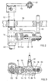
- FIG. 2 and 3 a second embodiment of the Invention in which a first in a base plate 50 Shaft 52 is rotatably mounted.
- first lever 54 constructed in a housing-like manner, non-rotatably mounted, which contains two parallel legs 54a and 54b. Between free ends of the legs 54a and 54b is one to the shaft 52 Clamped parallel axis, which is a rotatable crowned or barrel-shaped roller 58 carries.
- a second shaft 66 is rotatable in the base plate 50 mounted, which is aligned parallel to the first shaft 52, and at the bottom with respect to FIG. 2 plate-shaped second lever 68 is rotatably mounted.
- the second shaft 66 can be equipped with a switching element for a Gearboxes are connected, but not closer was shown.
- one with the first lever 54 non-rotatably connected and with the shaft 52 aligned shaft 69 with a switching element for a transmission keep in touch.
- the second lever 68 contains a substantially in Lever longitudinal direction extending longitudinal slot 74, which extends to the side facing away from the shaft 66 on both sides expands and forms two lateral bulges 76. By doing The longitudinal slot 74 guides the roller 58.
- an articulation point 72 provided, on which one end of a tension spring 78 engages, the other end of which is hooked into the first shaft 52.
- the circuit device according to FIGS. 2 and 3 differs differs from that shown in Fig. 1 mainly by the compact construction, which essentially results from that the tension spring 78 in the second embodiment between the second lever 68 and the first shaft 52 is attached. How the two work Embodiments are essentially the same.
- the switching device is in its neutral position in which the articulation point 72 is in an alignment line 82 with the first and second shafts 52, 66.
- the tension spring 78 is essentially relaxed and the roller is from the straight portion of the longitudinal slot 74th added.
- FIGS. 4 to 6 represent the switching device of FIGS. 2 and 3 in different deflected from the neutral position Positions.
- the deflection angle is ⁇ des first lever 54 relative to its neutral position 5 °
- the deflection angle ⁇ of the second lever 68 with respect to it Neutral position is 23 °.
- the non-neutral position is in Fig. 6 shown.
- a Return from the non-neutral position to the neutral position is only possible if the first lever 54 is reset.
- the dashed circle 84 in FIGS. 4 to 6 each indicates a virtual position of the articulation point 72, which is occupied will when the levers 54 and 68 from their neutral position below in a position that is a mirror image of the shown upper layer corresponds. So that's it Switching device suitable for a reversing gearbox from a forward gear to a neutral position Reverse gear can be switched.
Landscapes
- Engineering & Computer Science (AREA)
- General Engineering & Computer Science (AREA)
- Mechanical Engineering (AREA)
- Gear-Shifting Mechanisms (AREA)
- Arrangement Or Mounting Of Control Devices For Change-Speed Gearing (AREA)
- Control Of Transmission Device (AREA)
Applications Claiming Priority (4)
| Application Number | Priority Date | Filing Date | Title |
|---|---|---|---|
| DE19653852 | 1996-12-21 | ||
| DE19653852 | 1996-12-21 | ||
| DE19711237 | 1997-03-18 | ||
| DE19711237A DE19711237A1 (de) | 1996-12-21 | 1997-03-18 | Schalteinrichtung für ein Getriebe |
Publications (3)
| Publication Number | Publication Date |
|---|---|
| EP0849507A2 true EP0849507A2 (fr) | 1998-06-24 |
| EP0849507A3 EP0849507A3 (fr) | 1999-02-10 |
| EP0849507B1 EP0849507B1 (fr) | 2003-04-16 |
Family
ID=26032666
Family Applications (1)
| Application Number | Title | Priority Date | Filing Date |
|---|---|---|---|
| EP97122009A Expired - Lifetime EP0849507B1 (fr) | 1996-12-21 | 1997-12-13 | Tringlerie de changement de vitesses pour la transmission des efforts de selection |
Country Status (1)
| Country | Link |
|---|---|
| EP (1) | EP0849507B1 (fr) |
Cited By (2)
| Publication number | Priority date | Publication date | Assignee | Title |
|---|---|---|---|---|
| EP0860631B1 (fr) * | 1997-02-20 | 2002-04-17 | Automobiles Peugeot | Dispositif de transmission mécanique pour la commande d'une boíte de vitesses à rapports etages |
| CN104769337A (zh) * | 2012-10-19 | 2015-07-08 | 舍弗勒技术股份两合公司 | 机动车辆变速器的换挡设备 |
Families Citing this family (1)
| Publication number | Priority date | Publication date | Assignee | Title |
|---|---|---|---|---|
| DE102009006877A1 (de) | 2009-01-30 | 2010-08-05 | Dr. Ing. H.C. F. Porsche Aktiengesellschaft | Schaltvorrichtung für ein mehrstufiges Schaltgetriebe |
Citations (1)
| Publication number | Priority date | Publication date | Assignee | Title |
|---|---|---|---|---|
| EP0737826A1 (fr) | 1995-04-14 | 1996-10-16 | FIAT AUTO S.p.A. | Dispositif élastique pour le positionnement d'un levier de changement de vitesse |
Family Cites Families (4)
| Publication number | Priority date | Publication date | Assignee | Title |
|---|---|---|---|---|
| DE2027713A1 (de) * | 1970-06-05 | 1971-12-16 | Daimler Benz Ag, 7000 Stuttgart | Schaltgestange fur Getriebe |
| US4651583A (en) * | 1985-04-16 | 1987-03-24 | Nippon Cable System, Inc. | Locking mechanism |
| DE4206629A1 (de) * | 1992-03-03 | 1993-09-09 | Opel Adam Ag | Arretierungsmechanismus |
| US5537892A (en) * | 1994-01-31 | 1996-07-23 | Caterpillar Inc. | Control lever assembly and mounting apparatus |
-
1997
- 1997-12-13 EP EP97122009A patent/EP0849507B1/fr not_active Expired - Lifetime
Patent Citations (1)
| Publication number | Priority date | Publication date | Assignee | Title |
|---|---|---|---|---|
| EP0737826A1 (fr) | 1995-04-14 | 1996-10-16 | FIAT AUTO S.p.A. | Dispositif élastique pour le positionnement d'un levier de changement de vitesse |
Cited By (3)
| Publication number | Priority date | Publication date | Assignee | Title |
|---|---|---|---|---|
| EP0860631B1 (fr) * | 1997-02-20 | 2002-04-17 | Automobiles Peugeot | Dispositif de transmission mécanique pour la commande d'une boíte de vitesses à rapports etages |
| CN104769337A (zh) * | 2012-10-19 | 2015-07-08 | 舍弗勒技术股份两合公司 | 机动车辆变速器的换挡设备 |
| CN104769337B (zh) * | 2012-10-19 | 2016-12-14 | 舍弗勒技术股份两合公司 | 机动车辆变速器的换挡设备 |
Also Published As
| Publication number | Publication date |
|---|---|
| EP0849507A3 (fr) | 1999-02-10 |
| EP0849507B1 (fr) | 2003-04-16 |
Similar Documents
| Publication | Publication Date | Title |
|---|---|---|
| DE19549437C2 (de) | Schaltvorrichtung für ein automatisches Getriebe eines Kraftfahrzeugs | |
| DE69315160T2 (de) | Getriebe-Gangwechsel Steuersystem | |
| DE19882218B4 (de) | Getriebe mit einer Zentralschaltwelle | |
| DE19711237A1 (de) | Schalteinrichtung für ein Getriebe | |
| DE2620062A1 (de) | Wechselgetriebe | |
| WO2008003407A1 (fr) | Boîte de changement de vitesse | |
| DE19637254C2 (de) | Wählvorrichtung für ein Automatikgetriebe von Kraftfahrzeugen | |
| DE3023378C2 (de) | Schaltvorrichtung für eine Zapfwelle | |
| DE2938640C2 (de) | Schalteinrichtung für hydromechanische Schaltgetriebe, insb. für Ackerschlepper oder ähnliche Nutzfahrzeuge | |
| DE68919616T2 (de) | Schaltsperreneinheit eines Fahrzeuggetriebes. | |
| EP0699853B1 (fr) | Tringlerie de sélection des vitesses pour boîte de vitesse d'un véhicule | |
| DE102008022561B4 (de) | Schaltvorrichtung für ein Automatikgetriebe | |
| EP1836414A1 (fr) | Dispositif de selection conçu pour une boite de vitesses automatique d'un vehicule automobile | |
| EP1267240B1 (fr) | Changement de vitesse pour une boíte de vitesses manuelle d'un véhicule automobile | |
| EP0849507B1 (fr) | Tringlerie de changement de vitesses pour la transmission des efforts de selection | |
| EP1531290A2 (fr) | Dispositif de sélection de vitesse | |
| EP0928725B1 (fr) | Installation de frein de stationnement pour véhicules avec engrenage de changement vitesse | |
| EP1235006A1 (fr) | Dispositif de commande pour boítes de vitesses de véhicules à moteur avec verrouillage empêchant l'enclenchement de la marche arrière | |
| DE4428205A1 (de) | Betätigungseinrichtung zum Steuern des Gangwechsels eines Getriebes für ein Kraftfahrzeug | |
| DE3505586A1 (de) | Steuereinrichtung fuer eine kupplung und ein getriebe eines motorfahrzeugs | |
| DE69716869T2 (de) | Sicherheitseinrichtung für mechanisches schaltgetriebe | |
| DE3043466A1 (de) | Schaltvorrichtung fuer ein getriebe | |
| EP3817627B1 (fr) | Siège | |
| DE7802241U1 (de) | Schalteinrichtung für ein aus einem Haupt- und einem Zweibereichs-Gruppengetriebe bestehenden Zahnräderwechselgetriebe | |
| DE607043C (de) | Schaltvorrichtung fuer Zahnraederwechselgetriebe von Kraftfahrzeugen |
Legal Events
| Date | Code | Title | Description |
|---|---|---|---|
| PUAI | Public reference made under article 153(3) epc to a published international application that has entered the european phase |
Free format text: ORIGINAL CODE: 0009012 |
|
| AK | Designated contracting states |
Kind code of ref document: A2 Designated state(s): DE FR GB IT |
|
| AX | Request for extension of the european patent |
Free format text: AL;LT;LV;MK;RO;SI |
|
| PUAL | Search report despatched |
Free format text: ORIGINAL CODE: 0009013 |
|
| AK | Designated contracting states |
Kind code of ref document: A3 Designated state(s): AT BE CH DE DK ES FI FR GB GR IE IT LI LU MC NL PT SE |
|
| AX | Request for extension of the european patent |
Free format text: AL;LT;LV;MK;RO;SI |
|
| 17P | Request for examination filed |
Effective date: 19990706 |
|
| AKX | Designation fees paid |
Free format text: DE FR GB IT |
|
| 17Q | First examination report despatched |
Effective date: 20010424 |
|
| GRAG | Despatch of communication of intention to grant |
Free format text: ORIGINAL CODE: EPIDOS AGRA |
|
| RAP1 | Party data changed (applicant data changed or rights of an application transferred) |
Owner name: DEERE & COMPANY |
|
| APAB | Appeal dossier modified |
Free format text: ORIGINAL CODE: EPIDOS NOAPE |
|
| GRAG | Despatch of communication of intention to grant |
Free format text: ORIGINAL CODE: EPIDOS AGRA |
|
| GRAH | Despatch of communication of intention to grant a patent |
Free format text: ORIGINAL CODE: EPIDOS IGRA |
|
| GRAH | Despatch of communication of intention to grant a patent |
Free format text: ORIGINAL CODE: EPIDOS IGRA |
|
| GRAA | (expected) grant |
Free format text: ORIGINAL CODE: 0009210 |
|
| AK | Designated contracting states |
Designated state(s): DE FR GB IT |
|
| REG | Reference to a national code |
Ref country code: GB Ref legal event code: FG4D Free format text: NOT ENGLISH |
|
| REF | Corresponds to: |
Ref document number: 59709851 Country of ref document: DE Date of ref document: 20030522 Kind code of ref document: P |
|
| GBT | Gb: translation of ep patent filed (gb section 77(6)(a)/1977) | ||
| ET | Fr: translation filed | ||
| PLBE | No opposition filed within time limit |
Free format text: ORIGINAL CODE: 0009261 |
|
| STAA | Information on the status of an ep patent application or granted ep patent |
Free format text: STATUS: NO OPPOSITION FILED WITHIN TIME LIMIT |
|
| 26N | No opposition filed |
Effective date: 20040119 |
|
| PGFP | Annual fee paid to national office [announced via postgrant information from national office to epo] |
Ref country code: FR Payment date: 20061220 Year of fee payment: 10 |
|
| PGFP | Annual fee paid to national office [announced via postgrant information from national office to epo] |
Ref country code: GB Payment date: 20061222 Year of fee payment: 10 |
|
| PGFP | Annual fee paid to national office [announced via postgrant information from national office to epo] |
Ref country code: IT Payment date: 20061231 Year of fee payment: 10 |
|
| PGFP | Annual fee paid to national office [announced via postgrant information from national office to epo] |
Ref country code: DE Payment date: 20071120 Year of fee payment: 11 |
|
| GBPC | Gb: european patent ceased through non-payment of renewal fee |
Effective date: 20071213 |
|
| REG | Reference to a national code |
Ref country code: FR Ref legal event code: ST Effective date: 20081020 |
|
| PG25 | Lapsed in a contracting state [announced via postgrant information from national office to epo] |
Ref country code: GB Free format text: LAPSE BECAUSE OF NON-PAYMENT OF DUE FEES Effective date: 20071213 |
|
| PG25 | Lapsed in a contracting state [announced via postgrant information from national office to epo] |
Ref country code: FR Free format text: LAPSE BECAUSE OF NON-PAYMENT OF DUE FEES Effective date: 20071231 |
|
| PG25 | Lapsed in a contracting state [announced via postgrant information from national office to epo] |
Ref country code: IT Free format text: LAPSE BECAUSE OF NON-PAYMENT OF DUE FEES Effective date: 20071213 |
|
| PG25 | Lapsed in a contracting state [announced via postgrant information from national office to epo] |
Ref country code: DE Free format text: LAPSE BECAUSE OF NON-PAYMENT OF DUE FEES Effective date: 20090701 |