EP0849521B2 - Vorrichtung zur Kontrolle der Dampfströmung in elektrischen Dampf gebrauchenden Haushaltgeräten - Google Patents
Vorrichtung zur Kontrolle der Dampfströmung in elektrischen Dampf gebrauchenden Haushaltgeräten Download PDFInfo
- Publication number
- EP0849521B2 EP0849521B2 EP19960830630 EP96830630A EP0849521B2 EP 0849521 B2 EP0849521 B2 EP 0849521B2 EP 19960830630 EP19960830630 EP 19960830630 EP 96830630 A EP96830630 A EP 96830630A EP 0849521 B2 EP0849521 B2 EP 0849521B2
- Authority
- EP
- European Patent Office
- Prior art keywords
- tube
- steam
- supporting structure
- tongue
- plunger
- Prior art date
- Legal status (The legal status is an assumption and is not a legal conclusion. Google has not performed a legal analysis and makes no representation as to the accuracy of the status listed.)
- Expired - Lifetime
Links
- 230000033001 locomotion Effects 0.000 claims description 12
- 230000001105 regulatory effect Effects 0.000 claims description 8
- 230000001276 controlling effect Effects 0.000 claims description 6
- 239000000463 material Substances 0.000 claims description 5
- 230000000750 progressive effect Effects 0.000 claims description 4
- 230000008878 coupling Effects 0.000 claims 2
- 238000010168 coupling process Methods 0.000 claims 2
- 238000005859 coupling reaction Methods 0.000 claims 2
- 230000000694 effects Effects 0.000 claims 1
- XEEYBQQBJWHFJM-UHFFFAOYSA-N Iron Chemical compound [Fe] XEEYBQQBJWHFJM-UHFFFAOYSA-N 0.000 description 16
- 229910052742 iron Inorganic materials 0.000 description 8
- 238000005452 bending Methods 0.000 description 2
- 238000004140 cleaning Methods 0.000 description 1
- 230000000994 depressogenic effect Effects 0.000 description 1
- 235000000396 iron Nutrition 0.000 description 1
- 238000010409 ironing Methods 0.000 description 1
- 238000004519 manufacturing process Methods 0.000 description 1
- 238000000034 method Methods 0.000 description 1
- 238000003825 pressing Methods 0.000 description 1
- 230000000630 rising effect Effects 0.000 description 1
- 238000013020 steam cleaning Methods 0.000 description 1
Images



Classifications
-
- D—TEXTILES; PAPER
- D06—TREATMENT OF TEXTILES OR THE LIKE; LAUNDERING; FLEXIBLE MATERIALS NOT OTHERWISE PROVIDED FOR
- D06F—LAUNDERING, DRYING, IRONING, PRESSING OR FOLDING TEXTILE ARTICLES
- D06F75/00—Hand irons
- D06F75/08—Hand irons internally heated by electricity
- D06F75/10—Hand irons internally heated by electricity with means for supplying steam to the article being ironed
- D06F75/12—Hand irons internally heated by electricity with means for supplying steam to the article being ironed the steam being produced from water supplied to the iron from an external source
Definitions
- the subject of the present invention is a device for controlling the flow of steam in domestic electrical appliances that use steam, such as steam irons, steam cleaning machines, coffee machines with separate steam dispensing outlet, and so on.
- steam flow is controlled in such domestic electrical appliances by means of an externally operated valve fitted to the tube connecting the steam generator to the part that uses the steam.
- this valve is a needle valve in which the needle moves towards or away from a steam passage hole to vary its section and thus regulate the flow.
- the tube has to be cut and the valve connected up leaktightly to both ends of the tube.
- the leaktight connections may deteriorate and result in dangerous leakage of steam.
- JP-A-05-192498 discloses a device for controlling the flow of stream in a domestic electrical appliance comprising a steam generator, an iron body for using the steam, and a tube for conveying the steam from the steam generator to the iron body.
- the device comprises means for regulating the quantity of steam which flows towards the iron body.
- the steam regulating means comprises an electromechanical valve system which is relative expensive and also can be subject to failure, especially because their internal parts are in contact with the steam.
- EP-A-0.485.827 discloses a vapour controlling device for a domestic electric appliance, i.e. a vacuum cleaner, wherein a tube of elastically deformable material and able to convey the vapour from a vapour generator to the cleaning element is normally closed by a pressure element for the action of a spring.
- the pressure element is part of a lever which can rotate on a fixed pin.
- An electrical motor and a plurality of reduction gears associated thereto are provided for causing the rotation of the lever against the action of the spring.
- the electric motor can be operated by the user through drive elements mounted on a handle.
- the lever also comprises an external element by means of which it can be manually and temporarily rotated for removing the pressure element from the tube.
- This device has some drawbacks: first of all the tube, wherein the vapour flows, is normally closed by the action of the spring; further, for allowing the passage of the vapour, the electric motor must be actuated or a relative high force must be manually applied to the external element of the lever, against the action of such a spring; moreover, the quantity of vapour which flows through the tube (5) is very difficult to regulate, both with the electric motor and with the manual operable element.
- the object of the present invention is to overcome these drawbacks.
- a device for controlling the flow of steam in domestic electrical appliances comprising a steam generator, means for using the steam, a tube for conveying the steam from the steam generator to the steam using means, and regulating means for regulating the quantity of steam flowing to said steam using means, characterized in that the tube is made of elastically deformable material and in that the regulating means comprises a presser part able to cooperate with the tube and connected to an external actuating elementthrough mechanically operating means.
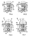
- the device of Fig. 1, indicated by the general reference 10, comprises a boxlike supporting structure 11, housed inside which is part of a tube T connecting a steam generator to a component that uses the steam in a domestic electrical appliance.
- the tube T is made of elastically deformable material and is contained between side walls 12 internal to the supporting structure 11 rising from a bottom wall 11A of the structure 11 and defining an S path for the length of tube within the supporting structure 11.
- the supporting structure includes suitable openings 11C (only one of which is shown, in dashes) through which the tube enters and exits from this structure with interference.
- the control device 10 works as follows, with reference to Figs. 2,3,4 and 5.
- the device Because control is achieved simply by constricting the tube T, the device includes no parts in contact with the steam so that the failures associated with known valves are avoided.
- the control device illustrated in Figs. 6 and 7, bearing the general reference 30, has the same boxlike supporting structure 11 seen in the previous device 10.
- the ridge 15 of the tongue 13 is depressed not by the slider 16 but by a screw 31 that screws into a hole 32 formed in the supporting structure 11.
- the head 33 of the screw 31 is on the outside of the structure 11, over the wall 11B, and is in the form of a knob. Turning this head 33 in one direction causes the end of the screw 31 progressively to bend the tongue 13, which in turn progressively constricts the tube T as shown in Fig. 7, and, of course, by turning the head 33 in the opposite direction the tube T returns progressively to its normal configuration.
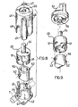
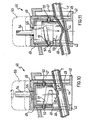
- Figs. 8,9,10 and 11 show a third version, in which control is once again by means of a rotary movement.
- the control device illustrated bearing the general reference 40, comprises a cylindrical housing 41 with a rhomboidal base 42 having two opposing holes 43 (only one of which is illustrated).
- the housing 41 has an inclined base 44 and two U-shaped cutouts 45 on opposite sides and of different depths formed in the cylindrical wall of the housing.
- a second cylindrical housing 46 having two opposing hollow columns 47 on its outside lined up with the holes 43 formed in the base 42 of the housing 41; two screws (not shown) pass through these columns 47 and holes 43 to fasten the two housings 41 and 46 together inside an apparatus that houses the device 40; the housings 41 and 46 thus form a supporting structure.
- the housing 46 contains two inverted U-shaped cutouts 48 of different depths superimposed on the cutouts 45 formed in the housing 41 to provide two openings on opposite sides; in particular the deeper cutout 48 is superimposed on the shallower cutout 45, while on the other hand the shallower cutout 48 is superimposed on the deeper cutout 45, so that the openings are at different heights.
- an actuating cylinder 49 and, coupled to it, a plunger 50 housed in the seat formed inside the housings 41 and 46.
- the cylinder 49 is provided with two opposing slots 51 extending along a portion of helix, in which two corresponding opposing radial pins 52 on the plunger 50 can slide.
- the cylinder 49 is rigidly connected to an external control knob 53 through a pin 54 of asymmetric section, integral with the cylinder, which passes through a hole 55 in the housing 46 and passes into a corresponding seat 56 in the knob.
- the plunger 50 is arcuate on its underside, its convexity being outwards.
- the tube T passes with interference through the abovementioned openings staggered at different heights, formed by the superimposition of the cutouts 45 and 48, and rests on the inclined bottom 44 leading from one opening to the other.
- the plunger 50 is positioned with its arcuate end against the tube T.
- Rotating the knob 53 in one direction rotates the cylinder 49 in the same direction and the slots 51 slide past the pins 52 in such a way that the plunger 50 is moved axially downwards, so that the rotary motion is converted into a translational motion.
- the plunger 50 progressively constricts the tube T, as shown in Fig. 11, so that the flow of steam through the tube is regulated.
- the knob 53 in the ,opposite direction the plunger 50 is moved axially upwards and the tube T returns progressively to its normal configuration.
- This last version also has the advantage that by an appropriate inclination of the slots of the cylinder, small rotations of the knob result in a relatively large stroke of the plunger, making it unnecessary to rotate the knob excessively to pass from one to the other of the two extreme control positions.
- the ends of the slots define these extreme control positions.
- Fig. 12 shows the application of the control device 10 to a steam iron with a separate boiler.
- the boiler is shown at A and the iron at B.
- the control device 10 is incorporated in the boiler A and all that can be seen of it is the control part 19.
- the tube T connects the boiler A to the iron B so that the steam is carried, as is known, from the boiler to the perforated plate of the iron B, from which the steam escapes during ironing. It is this flow of steam that can be controlled by means of the control part 19, through the process of constricting the tube T as has already been seen.
- control devices described above can however be incorporated in any domestic electrical steam appliance in which control of the flow of steam along the tube is required.
- the configuration of the various components of the three devices seen above can of course be varied, for example in order to satisfy different applications.
- the tongue used in the first two versions can be replaced by some other functionally equivalent presser part.
Landscapes
- Health & Medical Sciences (AREA)
- Public Health (AREA)
- Engineering & Computer Science (AREA)
- Textile Engineering (AREA)
- Lift Valve (AREA)
- Irons (AREA)
- Control Of Steam Boilers And Waste-Gas Boilers (AREA)
Claims (11)
- Vorrichtung (10, 20, 30) zur Steuerung des Dampfstromes in einem elektrischen Haushaltgerät, welches umfasst:(a) einen Dampferzeuger (A), Mittel (B) zum Handhaben des Dampfes, ein Rohr (T), welches aus elastisch verformbaren Material zur Förderung des Dampfes vom Dampferzeuger (A) zu den Dampf-Handhabungsmitteln (B) hergestellt ist, und(b) Reguliermittel zur Mengenregulierung des Dampfstromes zu den Handhabungsmittein (B),(c) das Rohr (T) ist in der Regel auf Grund seiner elastischen Fähigkeiten in einer geöffneten Position und(d) die Regulierungsmittel weisen einen Press-Einsatz (13, 50) auf, welcher mit dem Rohr (T) zusammenwirkt, um dieses zusammen zu pressen und um mindestens eine teilweise geschlossene Position unter Einwirkung der elastischen Kraft des verformbaren Materials einzunehmen und(e) verbunden mittels mechanischer Betriebsmittel (16, 49) mit einem externen Betätigungselement (19, 33, 53) und bewegbar zwischen einer nicht aktiven Position, zu welcher die geöffnete Position des Rohres (T) entspricht und mindestens einer Betriebsposition, zu welcher mindestens die teilweise geschlossene Position des Rohres (T) entspricht.
- Vorrichtung nach Anspruch 1, in welchem das Pressteil eine elastische Zunge (13) ist, welche an einem Ende mit einer Stützstruktur (11) fixiert ist, auf welche ein Schieber (16) wirkt, mit längsförmiger Ausbildung entlang einer geraden Führung (17) geführt, welche in der Stützstruktur (11) ausgebildet ist, und eine Kante (18) aufweist, welche in Bezug zur Führung (17) geneigt ist, und in Kontakt mit der Zunge (13) ist, wobei die Bewegung des Schiebers (16) eine zunehmende Presswirkung mit seiner Kante (18) auf die Zunge (13) ausübt.
- Vorrichtung nach Anspruch 2, in welcher die Kante (18) des Schiebers (16) gezahnt ist und auf einen Kamm (15) wirkt, der an der Zunge (13) ausgebildet ist.
- Vorrichtung nach Anspruch 1, in welcher das Pressteil eine elastische Zunge (13) ist, welche mit einem Ende an der Stützstruktur (11) fixiert ist, auf welches eine Schraube (31) wirkt, welche sich in eine Bohrung (32) schraubt, welche in der Stützstruktur (11) ausgebildet ist.
- Vorrichtung nach den Ansprüchen 2 oder 4, in welcher ein Stopzahn (20) angeordnet ist, welcher die Zunge (13) in einer Position maximaler sattelförmiger Einschnürung der Leitung (T) begrenzt.
- Vorrichtung nach den Ansprüche 2 oder 4, in welcher die Stützstruktur (11) Öffnungen beinhaltet, durch welche die Leitung (T) durch Presspassungen in die Struktur ein- und wieder austritt.
- Vorrichtung nach einem der Ansprüche 2, 3 und 6, in welcher die Stützstruktur (11) Einheiten (12) beinhaltet, welche einen S-förmigen Verlauf der Leitung (T) durch die Struktur (11) definiert.
- Vorrichtung nach Anspruch 1, in welchem das Pressteil ein Kolben (50) ist, welcher linear in einem Sitz bewegt werden kann, welcher in einer Stützstruktur (41, 46) ausgebildet ist, die externe Kontrolleinheit (53) drehbar ist, und Kupplungseinheiten (49, 51, 52) zur Verfügung stehen, um die Drehbewegung der Kontrolleinheit (53) in eine gradlinige, längsgerichtete Bewegung des Kolbens (50) umsetzt.
- Vorrichtung nach Anspruch 8, in welcher die Kupplungseinheiten beinhalten, eingeschlossen in besagtem Sitz, einen Aktivierungszylinder (49) welcher steif mit der externen Kontrolleinheit (53) verbunden ist und mit sich gegenüberliegenden Schlitzen (51) ausgebildet ist, welche sich entlang eines Abschnitts einer Helix erstrecken, in welcher zwei korrespondierende, sich radial gegenüberliegende Stifte (52), welche an dem Kolben (50) ausgebildet sind, gleiten können.
- Vorrichtung nach Anspruch 8, in welcher die Stützstruktur (41, 46) Öffnungen (45, 48) beinhaltet, durch welche die Leitung (T) durch Presspassungen in die Struktur ein- und wieder austritt.
- Vorrichtung nach den Ansprüchen 8 oder 10, in welcher die Stützstruktur (41, 46) Einheiten (44) beinhaltet, die einen geneigten Verlauf für die Leitung (T) innerhalb der Stützstruktur (41, 46) in Bezug der Richtung der Bewegung des Kolbens (50) definieren.
Priority Applications (4)
| Application Number | Priority Date | Filing Date | Title |
|---|---|---|---|
| EP19960830630 EP0849521B2 (de) | 1996-12-18 | 1996-12-18 | Vorrichtung zur Kontrolle der Dampfströmung in elektrischen Dampf gebrauchenden Haushaltgeräten |
| DE1996614554 DE69614554T3 (de) | 1996-12-18 | 1996-12-18 | Vorrichtung zur Kontrolle der Dampfströmung in dampfgebrauchenden elektrischen Haushaltsgeräten |
| ES96830630T ES2162649T5 (es) | 1996-12-18 | 1996-12-18 | Dispositivo para controlar la circulacion de vapor en aparatos electricos domesticos que utilizan vapor. |
| GR20010401522T GR3036662T3 (en) | 1996-12-18 | 2001-09-18 | Device for controlling the flow of steam in domestic steam using electrical appliances |
Applications Claiming Priority (1)
| Application Number | Priority Date | Filing Date | Title |
|---|---|---|---|
| EP19960830630 EP0849521B2 (de) | 1996-12-18 | 1996-12-18 | Vorrichtung zur Kontrolle der Dampfströmung in elektrischen Dampf gebrauchenden Haushaltgeräten |
Publications (3)
| Publication Number | Publication Date |
|---|---|
| EP0849521A1 EP0849521A1 (de) | 1998-06-24 |
| EP0849521B1 EP0849521B1 (de) | 2001-08-16 |
| EP0849521B2 true EP0849521B2 (de) | 2005-10-26 |
Family
ID=8226078
Family Applications (1)
| Application Number | Title | Priority Date | Filing Date |
|---|---|---|---|
| EP19960830630 Expired - Lifetime EP0849521B2 (de) | 1996-12-18 | 1996-12-18 | Vorrichtung zur Kontrolle der Dampfströmung in elektrischen Dampf gebrauchenden Haushaltgeräten |
Country Status (4)
| Country | Link |
|---|---|
| EP (1) | EP0849521B2 (de) |
| DE (1) | DE69614554T3 (de) |
| ES (1) | ES2162649T5 (de) |
| GR (1) | GR3036662T3 (de) |
Families Citing this family (4)
| Publication number | Priority date | Publication date | Assignee | Title |
|---|---|---|---|---|
| ITUD20010159A1 (it) * | 2001-10-02 | 2003-04-02 | Simac Vetrella Spa | Dispositivo e metodo per determinare la quantita' di liquido contenuto in un contenitore associato ad un elettrodomestico |
| ITUD20050114A1 (it) * | 2005-07-05 | 2007-01-06 | De Longhi Spa | Dispositivo per regolare il flusso di vapore in un elettrodomestico |
| FR2916004B1 (fr) * | 2007-05-07 | 2009-06-12 | Rowenta Werke Gmbh | Appareil pour le traitement du linge comprenant un dispositif pour controler le debit d'eau envoye vers un generateur de vapeur |
| DE102019006567B4 (de) * | 2019-09-17 | 2021-07-08 | Westinghouse Electric Germany Gmbh | Dampferzeugerflüssigkeitsabscheider und Verfahren zu dessen Herstellung |
Family Cites Families (5)
| Publication number | Priority date | Publication date | Assignee | Title |
|---|---|---|---|---|
| FR947662A (fr) * | 1947-05-21 | 1949-07-08 | Perfectionnements aux fers à repasser | |
| FR1343057A (fr) * | 1962-10-26 | 1965-11-26 | Perfectionnement aux fers à vapeur à réservoir séparé | |
| FR2512473A1 (fr) * | 1981-09-09 | 1983-03-11 | Maksa Christian | Dispositif de repassage a vapeur sous pression |
| CH682801A5 (fr) * | 1990-11-16 | 1993-11-30 | Radwulf Sa | Appareil électro-ménager. |
| JPH05192498A (ja) * | 1992-01-22 | 1993-08-03 | Matsushita Electric Ind Co Ltd | アイロン装置 |
-
1996
- 1996-12-18 EP EP19960830630 patent/EP0849521B2/de not_active Expired - Lifetime
- 1996-12-18 ES ES96830630T patent/ES2162649T5/es not_active Expired - Lifetime
- 1996-12-18 DE DE1996614554 patent/DE69614554T3/de not_active Expired - Fee Related
-
2001
- 2001-09-18 GR GR20010401522T patent/GR3036662T3/el not_active IP Right Cessation
Also Published As
| Publication number | Publication date |
|---|---|
| ES2162649T5 (es) | 2006-06-01 |
| ES2162649T3 (es) | 2002-01-01 |
| DE69614554T3 (de) | 2006-07-20 |
| DE69614554T2 (de) | 2002-06-06 |
| DE69614554D1 (de) | 2001-09-20 |
| EP0849521B1 (de) | 2001-08-16 |
| GR3036662T3 (en) | 2001-12-31 |
| EP0849521A1 (de) | 1998-06-24 |
Similar Documents
| Publication | Publication Date | Title |
|---|---|---|
| KR101018018B1 (ko) | 회전식 락킹/언락킹 제어 장치를 구비한 압력 조리 기구 | |
| EP0849521B1 (de) | Vorrichtung zur Kontrolle der Dampfströmung in elektrischen Dampf gebrauchenden Haushaltgeräten | |
| EP0927426B2 (de) | Regelknopf für haushaltgeräte | |
| CN1516765A (zh) | 电熨斗装置 | |
| KR970076137A (ko) | 타이머 캠스택 및 클러치 | |
| WO1998011574A9 (en) | Control knob used for household appliances | |
| US6268577B1 (en) | Push-pull switch operator | |
| US3546954A (en) | Device for actuating a limit control element | |
| CN209524132U (zh) | 一种电动执行器及其解锁手柄组件 | |
| CN209569386U (zh) | 一种电动执行器及其反馈开关组件 | |
| KR102231607B1 (ko) | 자가발전 스위치 | |
| US4782608A (en) | Variable steam control for electric iron | |
| US3688593A (en) | Apparatus for actuating a limit control element | |
| DE69600233T2 (de) | Küchenmachine mit einem Arbeitsgefäss mit einer Vorrichtung zum Reinigen der Innenwandung des Arbeitsgefässes | |
| KR200470169Y1 (ko) | 좌우 클릭형 단 조작수단을 갖는 수도밸브 카트리지 | |
| US5159722A (en) | Drive for a shower arm or a bidet device | |
| CN100564658C (zh) | 带有熨烫程序选择控制装置的熨斗 | |
| JPH0757279B2 (ja) | 電気式のスチームアイロン | |
| JPH0421519B2 (de) | ||
| DE102019212835A1 (de) | Steuerung einer Ventilvorrichtung | |
| JP2005337279A (ja) | モータ式往復駆動装置並びにモータ式往復駆動装置に用いられる可動軸体、回転筒体、ピニオン、可動軸体用取り付け部材、往復移動部材、収納ケース、ローラー、可動レバー、第1接片、第2接片及び接片取り付け基板 | |
| KR100460723B1 (ko) | 차량용 자동 변속기의 변속레버 작동장치 | |
| KR890000692Y1 (ko) | 푸쉬버튼식 급수 선택장치를 가진 세탁기 | |
| DE10321857B4 (de) | Elektrischer Schalter | |
| CN209511232U (zh) | 一种电动执行器及其传动轴连接装置 |
Legal Events
| Date | Code | Title | Description |
|---|---|---|---|
| PUAI | Public reference made under article 153(3) epc to a published international application that has entered the european phase |
Free format text: ORIGINAL CODE: 0009012 |
|
| AK | Designated contracting states |
Kind code of ref document: A1 Designated state(s): DE ES FR GR IT |
|
| AX | Request for extension of the european patent |
Free format text: AL;LT;LV;RO;SI |
|
| RIN1 | Information on inventor provided before grant (corrected) |
Inventor name: OSTINELLI, ALESSANDRO Inventor name: FRIARGIU, AMOS Inventor name: POZZOBON, SILVANO |
|
| 17P | Request for examination filed |
Effective date: 19980730 |
|
| AKX | Designation fees paid | ||
| RBV | Designated contracting states (corrected) | ||
| RBV | Designated contracting states (corrected) |
Designated state(s): DE ES FR GR IT |
|
| RAP1 | Party data changed (applicant data changed or rights of an application transferred) |
Owner name: SIMAC-VETRELLA SPA |
|
| 17Q | First examination report despatched |
Effective date: 20000210 |
|
| GRAG | Despatch of communication of intention to grant |
Free format text: ORIGINAL CODE: EPIDOS AGRA |
|
| GRAG | Despatch of communication of intention to grant |
Free format text: ORIGINAL CODE: EPIDOS AGRA |
|
| GRAH | Despatch of communication of intention to grant a patent |
Free format text: ORIGINAL CODE: EPIDOS IGRA |
|
| GRAH | Despatch of communication of intention to grant a patent |
Free format text: ORIGINAL CODE: EPIDOS IGRA |
|
| GRAA | (expected) grant |
Free format text: ORIGINAL CODE: 0009210 |
|
| AK | Designated contracting states |
Kind code of ref document: B1 Designated state(s): DE ES FR GR IT |
|
| REF | Corresponds to: |
Ref document number: 69614554 Country of ref document: DE Date of ref document: 20010920 |
|
| ITF | It: translation for a ep patent filed | ||
| ET | Fr: translation filed | ||
| REG | Reference to a national code |
Ref country code: ES Ref legal event code: FG2A Ref document number: 2162649 Country of ref document: ES Kind code of ref document: T3 |
|
| PLBQ | Unpublished change to opponent data |
Free format text: ORIGINAL CODE: EPIDOS OPPO |
|
| PLBI | Opposition filed |
Free format text: ORIGINAL CODE: 0009260 |
|
| 26 | Opposition filed |
Opponent name: ALFRED KAERCHER GMBH & CO. Effective date: 20020515 |
|
| PLBF | Reply of patent proprietor to notice(s) of opposition |
Free format text: ORIGINAL CODE: EPIDOS OBSO |
|
| PLBF | Reply of patent proprietor to notice(s) of opposition |
Free format text: ORIGINAL CODE: EPIDOS OBSO |
|
| REG | Reference to a national code |
Ref country code: FR Ref legal event code: TP Ref country code: FR Ref legal event code: RM Ref country code: FR Ref legal event code: CD |
|
| RAP2 | Party data changed (patent owner data changed or rights of a patent transferred) |
Owner name: DE' LONGHI S.P.A. |
|
| PUAH | Patent maintained in amended form |
Free format text: ORIGINAL CODE: 0009272 |
|
| STAA | Information on the status of an ep patent application or granted ep patent |
Free format text: STATUS: PATENT MAINTAINED AS AMENDED |
|
| 27A | Patent maintained in amended form |
Effective date: 20051026 |
|
| AK | Designated contracting states |
Kind code of ref document: B2 Designated state(s): DE ES FR GR IT |
|
| PG25 | Lapsed in a contracting state [announced via postgrant information from national office to epo] |
Ref country code: IT Free format text: LAPSE BECAUSE OF NON-PAYMENT OF DUE FEES Effective date: 20051218 |
|
| REG | Reference to a national code |
Ref country code: GR Ref legal event code: EP Ref document number: 20060400187 Country of ref document: GR |
|
| REG | Reference to a national code |
Ref country code: ES Ref legal event code: DC2A Date of ref document: 20060126 Kind code of ref document: T5 |
|
| ET3 | Fr: translation filed ** decision concerning opposition | ||
| PGFP | Annual fee paid to national office [announced via postgrant information from national office to epo] |
Ref country code: DE Payment date: 20070110 Year of fee payment: 11 |
|
| PGFP | Annual fee paid to national office [announced via postgrant information from national office to epo] |
Ref country code: ES Payment date: 20070129 Year of fee payment: 11 |
|
| PGFP | Annual fee paid to national office [announced via postgrant information from national office to epo] |
Ref country code: GR Payment date: 20070102 Year of fee payment: 11 |
|
| PGFP | Annual fee paid to national office [announced via postgrant information from national office to epo] |
Ref country code: FR Payment date: 20061229 Year of fee payment: 11 |
|
| PG25 | Lapsed in a contracting state [announced via postgrant information from national office to epo] |
Ref country code: GR Free format text: LAPSE BECAUSE OF NON-PAYMENT OF DUE FEES Effective date: 20060127 Ref country code: DE Free format text: LAPSE BECAUSE OF NON-PAYMENT OF DUE FEES Effective date: 20080701 |
|
| REG | Reference to a national code |
Ref country code: FR Ref legal event code: ST Effective date: 20081020 |
|
| REG | Reference to a national code |
Ref country code: ES Ref legal event code: FD2A Effective date: 20071219 |
|
| PG25 | Lapsed in a contracting state [announced via postgrant information from national office to epo] |
Ref country code: FR Free format text: LAPSE BECAUSE OF NON-PAYMENT OF DUE FEES Effective date: 20071231 Ref country code: ES Free format text: LAPSE BECAUSE OF NON-PAYMENT OF DUE FEES Effective date: 20071219 |