EP0849533B1 - Brenneranordnung für eine Gasturbine - Google Patents
Brenneranordnung für eine Gasturbine Download PDFInfo
- Publication number
- EP0849533B1 EP0849533B1 EP97810834A EP97810834A EP0849533B1 EP 0849533 B1 EP0849533 B1 EP 0849533B1 EP 97810834 A EP97810834 A EP 97810834A EP 97810834 A EP97810834 A EP 97810834A EP 0849533 B1 EP0849533 B1 EP 0849533B1
- Authority
- EP
- European Patent Office
- Prior art keywords
- burner
- lance
- axis
- fuel
- outlet openings
- Prior art date
- Legal status (The legal status is an assumption and is not a legal conclusion. Google has not performed a legal analysis and makes no representation as to the accuracy of the status listed.)
- Expired - Lifetime
Links
Images


Classifications
-
- F—MECHANICAL ENGINEERING; LIGHTING; HEATING; WEAPONS; BLASTING
- F23—COMBUSTION APPARATUS; COMBUSTION PROCESSES
- F23C—METHODS OR APPARATUS FOR COMBUSTION USING FLUID FUEL OR SOLID FUEL SUSPENDED IN A CARRIER GAS OR AIR
- F23C7/00—Combustion apparatus characterised by arrangements for air supply
- F23C7/02—Disposition of air supply not passing through burner
-
- F—MECHANICAL ENGINEERING; LIGHTING; HEATING; WEAPONS; BLASTING
- F23—COMBUSTION APPARATUS; COMBUSTION PROCESSES
- F23D—BURNERS
- F23D14/00—Burners for combustion of a gas, e.g. of a gas stored under pressure as a liquid
- F23D14/46—Details
- F23D14/72—Safety devices, e.g. operative in case of failure of gas supply
- F23D14/76—Protecting flame and burner parts
-
- F—MECHANICAL ENGINEERING; LIGHTING; HEATING; WEAPONS; BLASTING
- F23—COMBUSTION APPARATUS; COMBUSTION PROCESSES
- F23D—BURNERS
- F23D17/00—Burners for combustion simultaneously or alternately of gaseous or liquid or pulverulent fuel
- F23D17/002—Burners for combustion simultaneously or alternately of gaseous or liquid or pulverulent fuel gaseous or liquid fuel
-
- F—MECHANICAL ENGINEERING; LIGHTING; HEATING; WEAPONS; BLASTING
- F23—COMBUSTION APPARATUS; COMBUSTION PROCESSES
- F23C—METHODS OR APPARATUS FOR COMBUSTION USING FLUID FUEL OR SOLID FUEL SUSPENDED IN A CARRIER GAS OR AIR
- F23C2900/00—Special features of, or arrangements for combustion apparatus using fluid fuels or solid fuels suspended in air; Combustion processes therefor
- F23C2900/07002—Premix burners with air inlet slots obtained between offset curved wall surfaces, e.g. double cone burners
-
- F—MECHANICAL ENGINEERING; LIGHTING; HEATING; WEAPONS; BLASTING
- F23—COMBUSTION APPARATUS; COMBUSTION PROCESSES
- F23D—BURNERS
- F23D2900/00—Special features of, or arrangements for burners using fluid fuels or solid fuels suspended in a carrier gas
- F23D2900/00015—Pilot burners specially adapted for low load or transient conditions, e.g. for increasing stability
-
- F—MECHANICAL ENGINEERING; LIGHTING; HEATING; WEAPONS; BLASTING
- F23—COMBUSTION APPARATUS; COMBUSTION PROCESSES
- F23D—BURNERS
- F23D2900/00—Special features of, or arrangements for burners using fluid fuels or solid fuels suspended in a carrier gas
- F23D2900/00016—Preventing or reducing deposit build-up on burner parts, e.g. from carbon
Definitions
- the present invention relates to the field of Burner technology for gas turbines. It relates to a burner arrangement for a gas turbine, comprising at least one in Plenum of the gas turbine arranged burner, which with a internal injection chamber opens into a combustion chamber and outside with compressed air from a compressor stage of the gas turbine is applied, and a fuel lance assigned to the burner for the optional supply of liquid and / or gaseous fuels, which fuel lance is a central Liquid fuel pipe and a the liquid fuel pipe Has concentrically surrounding pilot gas pipe, the Tubes in a lance head at the top of the fuel lance end in associated outlet openings, and which fuel lance with the lance head in with the injection chamber in Connected inner tube of the burner is insertable.
- Such a burner arrangement is e.g. from the German Publication DE-A1-43 06 956 known.
- the burner lance is usually a two-fuel lance ("dual fuel lance"), i.e. in the fuel lance can optionally use gaseous fuel (pilot gas) and liquid fuel (usually an oil-water mixture) are fed. These are concentric in the lance appropriate pipes (liquid fuel pipe, pilot gas pipe) arranged, the channels for the gas and the liquid fuel form. The channels end at the lance tip (in the lance head) in associated outlet openings for the respective fuel. The lance is in a corresponding position with the lance head Inner tube of the burner, so that the exiting Fuel in the injection chamber connected to the inner tube arrives.
- the inner liquid fuel pipe flows (Liquid fuel channel) of the fuel lance an oil-water mixture.
- Flows in the start phase in contrast, in gas operation, pilot gas in the ring-shaped pilot gas channel between the liquid fuel pipe and the pilot gas pipe.
- pilot gas in the ring-shaped pilot gas channel between the liquid fuel pipe and the pilot gas pipe A the two fuel channels are always out of operation. Sometimes both channels are not used at the same time.
- the task is the one mentioned in your burner arrangement Kind of solved by protecting against intrusion of hot gases and / or hot liquid fuel into the outlet openings of the pipes when not in use Pipes in the lance head in the immediate vicinity of the outlet openings an additional opening is provided for the pipes is through which compressed air flows into the injection chamber, and that means are provided which compressed air the plenum surrounding the burner to the additional opening to lead. This will immediately on the lance head An air screen is located near the outlet openings of the fuel pipes generates a backflow into the outlet openings safely prevented. Because the compressed air required for this is direct is removed from the surrounding plenum on the burner, there are no additional lines in the lance and to the lance and associated connections, valves and the like.
- a first preferred embodiment of the burner arrangement according to the invention is characterized in that the means to guide the compressed air include a space which in the flow direction in front of the lance head between the pilot gas pipe and the inner tube of the burner is arranged, that the space with the plenum surrounding the burner via at least one from outside through the burner the inner tube leading inlet bore is connected to that of the Gap with the additional opening over at least a compressed air duct led through the lance head stands, and that the space is annular and concentrically surrounds the pilot gas pipe.
- the gap can be easily formed by that the (outer) pilot gas pipe of the lance in the direction of flow in front of the lance head in the outside diameter compared to the Inner tube of the burner is significantly reduced.
- the inlet holes and compressed air ducts require very little change on the burner or lance head.
- Burner arrangement is characterized in that several Inlet holes around the burner axis or lance axis are distributed that several compressed air channels around the Burner axis or lance axis are arranged distributed around and that the compressed air channels are inclined in the direction of flow Run the burner axis or lance axis.
- the outlet opening for the liquid fuel in the lance head is preferably arranged centrally, and the additional The opening in the lance head is preferably designed as a ring opening, which is the central outlet for the liquid fuel concentrically surrounds. This creates an air jacket generates the central outlet for the liquid fuel encloses and shields in a ring.
- the burner arrangement 1 is a first general embodiment in longitudinal section for a burner arrangement according to the present Invention reproduced.
- the burner arrangement 1 comprises a burner 2, in the present case as a double-cone burner is trained.
- the burner 2 encloses an injection chamber 8, in a combustion chamber, not shown opens (see DE-A1-43 06 956).
- the burner is outside surrounded by the plenum 7 of the gas turbine, which with compressed air from the compressor stage of the gas turbine.
- An inner tube 6 is arranged in the center of the burner 2, in which has a fuel lance 9 with an outer tube 10 and a lance tip is inserted, which is the end of a pilot gas pipe 11 and the adjoining lance head 12 includes.
- the burner 2 further comprises two external ones Main gas channels 3 and 4 (see also Fig. 2) through which the Main gas introduced and through a variety of inflow openings 5 (of which in Fig. 1 for the sake of clarity only five are shown as examples) in the injection chamber 8 is injected.
- the outside diameter of the pilot gas pipe 11 is opposite to that Inner diameter of the inner tube 6 (at least immediately behind the lance head 12) significantly reduced, so that between the pilot gas pipe 11 and the inner pipe 6 an annular space 13 results.
- This space 13 can - as from the cross section in Fig. 2 is clear - by two opposite Inlet holes 14 and 15 compressed air from the inflow surrounding plenum 7 and is there to form a Air screen in the exit area of the lance head 12 for Available.
- the formation of the air screen can be different Way and is to be based on two exemplary embodiments 3 and 4 are explained, the show the inner structure in the area of the lance head 12.
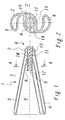
- Fig. 3 shows a first embodiment in longitudinal section (Partial figure (b)) and in cross section (partial figure (a)) along level B-B from sub-figure (b).
- the in the inner tube 6 of the burner 2 stuck fuel lance 9 includes next to that already mentioned pilot gas pipe 11 and the lance head 12 a concentric Liquid fuel tube arranged in the pilot gas tube 11 19.
- the liquid fuel brought up and through an associated outlet opening 20 in Lance head 12 injected into the injection space 8.
- With gas operation becomes pilot gas in the pilot gas channel 16 between the liquid fuel pipe 19 and the pilot gas pipe 11 and through several outlet openings 23 and 23a-c in the lance head injected into the injection chamber 8.
- the outlet openings 23a-c are formed by the liquid fuel pipe 19 at the tip 21 a cross section in the form of a circular bore of the pilot gas pipe 11 inscribed Triangle (see Fig. 3 (a)).
- annular opening 17 is provided, which is the central Outlet opening 22 of the liquid fuel channel 20 concentrically surrounds.
- the ring opening 17 is by several (three) compressed air ducts distributed around the lance axis 18 or 18a-c with compressed air from the gap 13 supplied.
- the compressed air channels 18 and 18a-c are located in the radial direction outside the outlet openings 23 or 23a-c, which open into the ring opening 17.
- the compressed air channels 18 or 18a-c and the inner wall of the ring opening 17th are preferably oblique to the burner axis or lance axis trained to run. This forms the emerging Compressed air a conically tapered air screen that a backflow of hot gases and / or hot oil from the Injection chamber 8 in one of the (just not used) outlet openings 22 or 23, 23a-c effectively prevented.
- FIG. 4 A second exemplary embodiment is shown in FIG. 4.
- the one in the inner tube 6 of the burner 2 comprises Fuel lance 9 an outer pilot gas tube 24, which is concentric surrounds a central liquid fuel tube 31.
- the liquid fuel formed by the two pipes 24 and 31 and pilot gas channels 32 and 25 correspond to the channels 20 and 16 from FIG. 3.
- the tubes 24 and 31 also end in here the lance head 12, which also has an annular opening 27, which is the central outlet opening 33 for the liquid fuel channel 32 concentrically surrounds.
- the compressed air for the ring opening 27 is made of the annular space 26, which in connection with the plenum via the inlet bores 14, 15 stands radially inward over a plurality of (six) directed compressed air channels 28 brought up.
- the pilot gas is not in this embodiment in the Ring opening 27 injected, but by a plurality of (Six) separate outlet openings 29 that are connected to the pilot gas channel 25 via corresponding pilot gas bores 30 in connection stand.
- the outlet openings 29 are outside the ring opening 27.
- the air screen generated with the ring opening 27 not only shields the lance head 12 as a whole but also separates between the outlet openings 29 for the pilot gas and the outlet opening 33 for the Liquid fuel, which in particular causes a backflow effective between the different outlet openings of the lance is prevented.
- the limited space in the lance head 12 is used particularly well when the outlet openings 29 for the pilot gas or pilot gas bores 30 and the compressed air channels 28 around the burner axis or lance axis are arranged alternately around.
- the invention results in a burner arrangement, effective in a simple manner with little effort prevents hot gases and / or hot oil from escaping the burner into the unused channels of the burner lance can flow back.
Landscapes
- Engineering & Computer Science (AREA)
- Chemical & Material Sciences (AREA)
- Combustion & Propulsion (AREA)
- Mechanical Engineering (AREA)
- General Engineering & Computer Science (AREA)
- Nozzles For Spraying Of Liquid Fuel (AREA)
- Pre-Mixing And Non-Premixing Gas Burner (AREA)
- Spray-Type Burners (AREA)
- Gas Burners (AREA)
Description
Es zeigen
- Fig. 1
- im Längsschnitt ein erstes allgemeines Ausführungsbeispiel für eine Brenneranordnung gemäss vorliegender Erfindung;
- Fig. 2
- den Querschnitt durch die Brenneranordnung gemäss Fig. 1 entlang der Ebene A-A mit den Einlassbohrungen für die abschirmende Druckluft;
- Fig. 3
- im Längsschnitt (Teilfigur (b)) und im Querschnitt (Teilfigur (a)) entlang der Ebene B-B aus Teilfigur (b) ein zweites bevorzugtes Ausführungsbeispiel für eine erfindungsgemässe Brenneranordnung mit gemeinsamer Ringöffnung für die Druckluft und das Pilotgas; und
- Fig. 4
- in der Frontalansicht (Teilfigur (a)), im Längsschnitt (Teilfigur(b)) und im Querschnitt (Teilfigur(c)) entlang der Ebene C-C in Teilfigur (b) ein drittes bevorzugtes Ausführungsbeispiel für eine erfindungsgemässe Brenneranordnung mit einer Plazierung des Luftschirms zwischen dem Flüssigbrennstoffaustritt und dem Pilotgasaustritt.
- 1
- Brenneranordnung
- 2
- Brenner (insb. Doppelkegelbrenner)
- 3,4
- Hauptgaskanal
- 5
- Einströmöffnung
- 6
- Innenrohr (Brenner)
- 7
- Plenum
- 8
- Einspritzraum
- 9
- Brennstofflanze
- 10
- Aussenrohr
- 11
- Pilotgasrohr
- 12
- Lanzenkopf
- 13
- Zwischenraum (ringförmig)
- 14,15
- Einlassbohrung (Druckluft)
- 16
- Pilotgaskanal
- 17
- Ringöffnung
- 18,18a-c
- Druckluftkanal
- 19
- Flüssigbrennstoffrohr
- 20
- Flüssigbrennstoffkanal
- 21
- Spitze (Flüssigbrennstoffrohr)
- 22
- Austrittsöffnung (Flüssigbrennstoffkanal)
- 23,23a-c
- Austrittsöffnung (Pilotgaskanal)
- 24
- Pilotgasrohr
- 25
- Pilotgaskanal
- 26
- Zwischenraum (ringförmig)
- 27
- Ringöffnung
- 28
- Druckluftkanal
- 29
- Austrittsöffnung (Pilotgaskanal)
- 30
- Pilotgasbohrung
- 31
- Flüssigbrennstoffrohr
- 32
- Flüssigbrennstoffkanal
- 33
- Austrittsöffnung (Flüssigbrennstoffkanal)
Claims (10)
- Brenneranordnung (1) für eine Gasturbine, umfassend wenigstens einen im Plenum (7) der Gasturbine angeordneten Brenner (2), welcher mit einem innenliegenden Einspritzraum (8) in eine Brennkammer mündet und aussen mit Druckluft von einer Kompressorstufe der Gasturbine beaufschlagt ist, sowie eine dem Brenner (2) zugeordnete Brennstofflanze (9) für die wahlweise Zufuhr von flüssigen und/oder gasförmigen Brennstoffen, welche Brennstofflanze (9) ein zentrales Flüssigbrennstoffrohr (19, 31) und ein das Flüssigbrennstoffrohr (19, 31) konzentrisch umgebendes Pilotgasrohr (11, 24) aufweist, wobei die Rohre (11, 19, 24, 31) in einem Lanzenkopf (12) an der Spitze der Brennstofflanze (9) in zugehörigen Austrittsöffnungen (22, 23, 23a-c, 29, 33) enden, und welche Brennstofflanze (9) mit dem Lanzenkopf (12) in ein mit dem Einspritzraum (8) in Verbindung stehendes Innenrohr (6) des Brenners (2) einführbar ist, dadurch gekennzeichnet, dass zum Schutz vor einem Eindringen von heissen Gasen und/oder heissem Flüssigbrennstoff in die Austrittsöffnungen (22, 23, 23a-c, 29, 33) der Rohre (11, 19, 24, 31) bei Nichtbenutzung dieser Rohre im Lanzenkopf (12) in unmittelbarer Nähe der Austrittsöffnungen (22, 23, 23a-c, 29, 33) der Rohre (11, 19, 24, 31) eine zusätzliche Oeffnung (17, 27) vorgesehen ist, durch welche Druckluft in den Einspritzraum (8) ausströmt, und dass Mittel vorgesehen sind, welche Druckluft aus dem den Brenner (2) umgebenden Plenum (7) zu der zusätzlichen Oeffnung (17, 27) führen.
- Brenneranordnung nach Anspruch 1, dadurch gekennzeichnet, dass die Mittel zur Führung der Druckluft einen Zwischenraum (13, 26) umfassen, welcher in Strömungsrichtung vor dem Lanzenkopf (12) zwischen dem Pilotgasrohr (11) und dem Innenrohr (6) des Brenners (2) angeordnet ist, dass der Zwischenraum (13, 26) mit dem den Brenner (2) umgebenden Plenum (7) über wenigstens eine von aussen durch den Brenner (2) hindurch in das Innenrohr (6) führende Einlassbohrung (14, 15) verbunden ist, und dass der Zwischenraum (13, 26) mit der zusätzlichen Oeffnung (17, 27) über wenigstens einen durch den Lanzenkopf (12) geführten Druckluftkanal (18, 18a-c, 28) in Verbindung steht.
- Brenneranordnung nach Anspruch 2, dadurch gekennzeichnet, dass der Zwischenraum (13, 26) ringförmig ausgebildet ist und das Pilotgasrohr (11) konzentrisch umgibt.
- Brenneranordnung nach einem der Ansprüche 2 und 3, dadurch gekennzeichnet, dass mehrere Einlassbohrungen (14, 15) um die Brennerachse bzw. Lanzenachse herum verteilt angeordnet sind.
- Brenneranordnung nach einem der Ansprüche 2 bis 4, dadurch gekennzeichnet, dass mehrere Druckluftkanäle (18, 18a-c, 28) um die Brennerachse bzw. Lanzenachse herum verteilt angeordnet sind.
- Brenneranordnung nach Anspruch 5, dadurch gekennzeichnet, dass die Druckluftkanäle (18, 18a-c, 28) in Strömungsrichtung schräg zur Brennerachse bzw. Lanzenachse hin verlaufen.
- Brenneranordnung nach einem der Ansprüche 1 bis 6, dadurch gekennzeichnet, dass die Austrittsöffnung (22, 33) für den Flüssigbrennstoff im Lanzenkopf (12) zentral angeordnet ist, und dass die zusätzliche Oeffnung im Lanzenkopf (12) als Ringöffnung (17, 27) ausgebildet ist, welche die zentrale Austrittsöffnung (22, 33) für den Flüssigbrennstoff konzentrisch umgibt.
- Brenneranordnung nach Anspruch 7, dadurch gekennzeichnet, dass mehrere Austrittsöffnungen (23, 23a-c) für das Pilotgas um die Brennerachse bzw. Lanzenachse herum verteilt angeordnet sind, und dass die Austrittsöffnungen (23, 23a-c) in die Ringöffnung (17) münden.
- Brenneranordnung nach Anspruch 7, dadurch gekennzeichnet, dass mehrere Austrittsöffnungen (29) für das Pilotgas um die Brennerachse bzw. Lanzenachse herum verteilt angeordnet sind, und dass die Austrittsöffnungen (29) ausserhalb der Ringöffnung (27) liegen.
- Brenneranordnung nach Anspruch 9, dadurch gekennzeichnet, dass mehrere Druckluftkanäle (28) um die Brennerachse bzw. Lanzenachse herum verteilt angeordnet sind, und dass die Austrittsöffnungen (29) bzw. die Pilotgasbohrungen (30) und die Druckluftkanäle (28) um die Brennerachse bzw. Lanzenachse herum alternierend angeordnet sind.
Applications Claiming Priority (2)
| Application Number | Priority Date | Filing Date | Title |
|---|---|---|---|
| DE19652899 | 1996-12-19 | ||
| DE19652899A DE19652899A1 (de) | 1996-12-19 | 1996-12-19 | Brenneranordnung für eine Gasturbine |
Publications (3)
| Publication Number | Publication Date |
|---|---|
| EP0849533A2 EP0849533A2 (de) | 1998-06-24 |
| EP0849533A3 EP0849533A3 (de) | 1999-08-11 |
| EP0849533B1 true EP0849533B1 (de) | 2003-06-04 |
Family
ID=7815276
Family Applications (1)
| Application Number | Title | Priority Date | Filing Date |
|---|---|---|---|
| EP97810834A Expired - Lifetime EP0849533B1 (de) | 1996-12-19 | 1997-11-06 | Brenneranordnung für eine Gasturbine |
Country Status (5)
| Country | Link |
|---|---|
| US (1) | US6038863A (de) |
| EP (1) | EP0849533B1 (de) |
| JP (1) | JP3995067B2 (de) |
| CN (1) | CN1103024C (de) |
| DE (2) | DE19652899A1 (de) |
Families Citing this family (12)
| Publication number | Priority date | Publication date | Assignee | Title |
|---|---|---|---|---|
| JPH1162622A (ja) * | 1997-08-22 | 1999-03-05 | Toshiba Corp | 石炭ガス化複合発電設備およびその運転方法 |
| DE19905995A1 (de) * | 1999-02-15 | 2000-08-17 | Asea Brown Boveri | Brennstofflanze zum Eindüsen von flüssigen und/oder gasförmigen Brennstoffen in eine Brennkammer sowie Verfahren zum Betrieb einer solchen Brennstofflanze |
| DE10049203A1 (de) * | 2000-10-05 | 2002-05-23 | Alstom Switzerland Ltd | Verfahren zur Brennstoffeinleitung in einen Vormischbrenner |
| US6360776B1 (en) | 2000-11-01 | 2002-03-26 | Rolls-Royce Corporation | Apparatus for premixing in a gas turbine engine |
| GB2373043B (en) * | 2001-03-09 | 2004-09-22 | Alstom Power Nv | Fuel injector |
| EP1456583B1 (de) * | 2001-12-20 | 2007-10-10 | Alstom Technology Ltd | Verfahren zum Eindüsen eines Brennstoff-/Luftgemisches in eine Brennkammer |
| ES2616873T3 (es) | 2004-03-31 | 2017-06-14 | Ansaldo Energia Ip Uk Limited | Disposición de múltiples quemadores para hacer funcionar una cámara de combustión así como procedimiento para hacer funcionar la disposición de múltiples quemadores |
| CN101365913A (zh) * | 2005-11-04 | 2009-02-11 | 阿尔斯托姆科技有限公司 | 燃料喷管 |
| JP4764391B2 (ja) * | 2007-08-29 | 2011-08-31 | 三菱重工業株式会社 | ガスタービン燃焼器 |
| EP2693124A1 (de) * | 2012-08-02 | 2014-02-05 | Siemens Aktiengesellschaft | Pilotbrenner, Brenner, Brennkammer und Gasturbinenmotor |
| JP5913503B2 (ja) * | 2014-09-19 | 2016-04-27 | 三菱重工業株式会社 | 燃焼バーナ及び燃焼器、並びにガスタービン |
| US20180238548A1 (en) * | 2017-02-22 | 2018-08-23 | Delavan Inc | Passive purge injectors |
Family Cites Families (16)
| Publication number | Priority date | Publication date | Assignee | Title |
|---|---|---|---|---|
| NL130010C (de) * | 1966-01-27 | |||
| DE1992617U (de) * | 1968-05-29 | 1968-08-29 | Steinmueller Gmbh L & C | Brenner zur wahlweisen verbrennung von fluessigen und/oder gasfoermigen brennstoffen. |
| GB1284439A (en) * | 1969-12-09 | 1972-08-09 | Rolls Royce | Fuel injector for a gas turbine engine |
| US3763650A (en) * | 1971-07-26 | 1973-10-09 | Westinghouse Electric Corp | Gas turbine temperature profiling structure |
| GB2122333B (en) * | 1982-06-15 | 1985-08-14 | Rolls Royce | Improvements in or relating to dual fuel burners for gas turbine engines |
| FR2570473B1 (fr) * | 1984-09-19 | 1989-07-13 | Pillard Chauffage | Perfectionnements aux bruleurs a gaz a ecoulement parallele comportant une rosace et un moyeu d'accrochage de flamme concernant les bruleurs a gaz et l'alimentation independante en air central |
| EP0276696B1 (de) * | 1987-01-26 | 1990-09-12 | Siemens Aktiengesellschaft | Hybridbrenner für Vormischbetrieb mit Gas und/oder Öl, insbesondere für Gasturbinenanlagen |
| DE4109304A1 (de) * | 1991-03-21 | 1992-09-24 | Siemens Ag | Verfahren zur verringerung der stickoxid-emission eines brenners bei heizoelbetrieb und gasbetrieb |
| US5337961A (en) * | 1992-12-07 | 1994-08-16 | General Electric Company | Ceramic tip and compliant attachment interface for a gas turbine fuel nozzle |
| DE4306956A1 (de) * | 1993-03-05 | 1994-09-08 | Abb Management Ag | Brennstoffzuführung für eine Gasturbine |
| GB9321505D0 (en) * | 1993-10-19 | 1993-12-08 | Europ Gas Turbines Ltd | Fuel injector |
| DE4424599A1 (de) * | 1994-07-13 | 1996-01-18 | Abb Research Ltd | Verfahren und Vorrichtung zum Betreiben eines kombinierten Brenners für flüssige und gasförmige Brennstoffe |
| DE19524213A1 (de) * | 1995-07-03 | 1997-01-09 | Abb Management Ag | Brennstoffzuführung für Gasturbinen mit Ringbrennkammer |
| DE19539246A1 (de) * | 1995-10-21 | 1997-04-24 | Asea Brown Boveri | Airblast-Zerstäuberdüse |
| DE19547914A1 (de) * | 1995-12-21 | 1997-06-26 | Abb Research Ltd | Vormischbrenner für einen Wärmeerzeuger |
| DE19618856B4 (de) * | 1996-05-10 | 2006-04-13 | Alstom | Vorrichtung zum Betreiben einer mit kombinierten Brennern für flüssige und gasförmige Brennstoffe bestückten Ringbrennkammer |
-
1996
- 1996-12-19 DE DE19652899A patent/DE19652899A1/de not_active Withdrawn
-
1997
- 1997-11-06 DE DE59710217T patent/DE59710217D1/de not_active Expired - Lifetime
- 1997-11-06 EP EP97810834A patent/EP0849533B1/de not_active Expired - Lifetime
- 1997-12-03 US US08/984,688 patent/US6038863A/en not_active Expired - Lifetime
- 1997-12-16 JP JP34634997A patent/JP3995067B2/ja not_active Expired - Fee Related
- 1997-12-19 CN CN97125577A patent/CN1103024C/zh not_active Expired - Lifetime
Also Published As
| Publication number | Publication date |
|---|---|
| CN1103024C (zh) | 2003-03-12 |
| JPH10185194A (ja) | 1998-07-14 |
| DE19652899A1 (de) | 1998-06-25 |
| EP0849533A2 (de) | 1998-06-24 |
| DE59710217D1 (de) | 2003-07-10 |
| CN1185565A (zh) | 1998-06-24 |
| US6038863A (en) | 2000-03-21 |
| JP3995067B2 (ja) | 2007-10-24 |
| EP0849533A3 (de) | 1999-08-11 |
Similar Documents
| Publication | Publication Date | Title |
|---|---|---|
| DE2143012C3 (de) | Brenneranordnung bei einer Gasturbinen-Brennkammer | |
| EP1456583B1 (de) | Verfahren zum Eindüsen eines Brennstoff-/Luftgemisches in eine Brennkammer | |
| DE102009003648B4 (de) | Brennstoffdüse, die einem Flammenhalteereignis standhält, und Verfahren zur Herstellung derselben | |
| EP1030109B1 (de) | Brennstofflanze zum Eindüsen von flüssigen und/oder gasförmigen Brennstoffen in eine Brennkammer | |
| EP0849533A2 (de) | Brenneranordnung für eine Gastrubine | |
| DE19905995A1 (de) | Brennstofflanze zum Eindüsen von flüssigen und/oder gasförmigen Brennstoffen in eine Brennkammer sowie Verfahren zum Betrieb einer solchen Brennstofflanze | |
| DE19859210A1 (de) | Brennstoff-Luft-Mischanordnung für Verbrennungsvorrichtungen | |
| DE1247752B (de) | Ringfoermige Brennkammer fuer Gasturbinentriebwerke | |
| DE19627203C2 (de) | Brenner | |
| EP0548396A1 (de) | Vorrichtung für die Vermischung zweier gasförmiger Komponenten und Brenner, in welchem diese Vorrichtung eingesetzt wird | |
| EP0757164A1 (de) | Brennstoffzuführung für Gasturbinen mit Ringbrennkammer | |
| DE1626044A1 (de) | Brenner,insbesondere fuer die Brennkammer eines Gasturbinentriebwerks | |
| DE19654008A1 (de) | Brenner | |
| DE4306956A1 (de) | Brennstoffzuführung für eine Gasturbine | |
| DE4446609B4 (de) | Vorrichtung zur Brennstoffzuführung zu einem sowohl für flüssige als auch für gasförmige Brennstoffe geeigneten Brenner | |
| DE10233805B4 (de) | Ringförmige Brennkammer für eine Gasturbine | |
| WO2007051705A1 (de) | Brennstofflanze | |
| EP1423647A1 (de) | Brennkammeranordnung | |
| DE10353423B3 (de) | Einspritzelement | |
| DE3901232C2 (de) | Brenner für die Brennkammer eines Gasturbinentriebwerks | |
| DE2610783C3 (de) | Einrichtung zur Stabilisierung der Strömung durch Radialbohrungen in rotierenden Hohlzylindern, insbesondere in Hohlwellen von Gasturbinen | |
| DE102014206139A1 (de) | Brennerkopf | |
| DE2364133C3 (de) | Brennermundstück | |
| DE2501340C3 (de) | Brennerdüse in einem Lot- und Anwärmbrenner | |
| DE9208993U1 (de) | Gasbrenner |
Legal Events
| Date | Code | Title | Description |
|---|---|---|---|
| PUAI | Public reference made under article 153(3) epc to a published international application that has entered the european phase |
Free format text: ORIGINAL CODE: 0009012 |
|
| AK | Designated contracting states |
Kind code of ref document: A2 Designated state(s): DE FR GB IT |
|
| AX | Request for extension of the european patent |
Free format text: AL;LT;LV;MK;RO;SI |
|
| PUAL | Search report despatched |
Free format text: ORIGINAL CODE: 0009013 |
|
| AK | Designated contracting states |
Kind code of ref document: A3 Designated state(s): AT BE CH DE DK ES FI FR GB GR IE IT LI LU MC NL PT SE |
|
| AX | Request for extension of the european patent |
Free format text: AL;LT;LV;MK;RO;SI |
|
| 17P | Request for examination filed |
Effective date: 19990918 |
|
| RIN1 | Information on inventor provided before grant (corrected) |
Inventor name: VALK, MARTIN, DR. Inventor name: MC MILLAN, ROBIN Inventor name: MARLOW, PAUL Inventor name: KELLER, JAKOB, PROF. DR. |
|
| AKX | Designation fees paid |
Free format text: DE FR GB IT |
|
| RAP1 | Party data changed (applicant data changed or rights of an application transferred) |
Owner name: ALSTOM |
|
| GRAG | Despatch of communication of intention to grant |
Free format text: ORIGINAL CODE: EPIDOS AGRA |
|
| 17Q | First examination report despatched |
Effective date: 20020604 |
|
| RAP1 | Party data changed (applicant data changed or rights of an application transferred) |
Owner name: ALSTOM (SWITZERLAND) LTD |
|
| GRAG | Despatch of communication of intention to grant |
Free format text: ORIGINAL CODE: EPIDOS AGRA |
|
| GRAH | Despatch of communication of intention to grant a patent |
Free format text: ORIGINAL CODE: EPIDOS IGRA |
|
| GRAH | Despatch of communication of intention to grant a patent |
Free format text: ORIGINAL CODE: EPIDOS IGRA |
|
| GRAA | (expected) grant |
Free format text: ORIGINAL CODE: 0009210 |
|
| AK | Designated contracting states |
Designated state(s): DE FR GB IT |
|
| REG | Reference to a national code |
Ref country code: GB Ref legal event code: FG4D Free format text: NOT ENGLISH |
|
| REF | Corresponds to: |
Ref document number: 59710217 Country of ref document: DE Date of ref document: 20030710 Kind code of ref document: P |
|
| GBT | Gb: translation of ep patent filed (gb section 77(6)(a)/1977) | ||
| ET | Fr: translation filed | ||
| PLBE | No opposition filed within time limit |
Free format text: ORIGINAL CODE: 0009261 |
|
| STAA | Information on the status of an ep patent application or granted ep patent |
Free format text: STATUS: NO OPPOSITION FILED WITHIN TIME LIMIT |
|
| 26N | No opposition filed |
Effective date: 20040305 |
|
| REG | Reference to a national code |
Ref country code: DE Ref legal event code: R082 Ref document number: 59710217 Country of ref document: DE Representative=s name: UWE ROESLER, DE |
|
| REG | Reference to a national code |
Ref country code: GB Ref legal event code: 732E Free format text: REGISTERED BETWEEN 20120802 AND 20120808 |
|
| REG | Reference to a national code |
Ref country code: DE Ref legal event code: R082 Ref document number: 59710217 Country of ref document: DE Representative=s name: ROESLER, UWE, DIPL.-PHYS.UNIV., DE Effective date: 20120713 Ref country code: DE Ref legal event code: R081 Ref document number: 59710217 Country of ref document: DE Owner name: ANSALDO ENERGIA IP UK LIMITED, GB Free format text: FORMER OWNER: ALSTOM (SWITZERLAND) LTD., BADEN, CH Effective date: 20120713 Ref country code: DE Ref legal event code: R081 Ref document number: 59710217 Country of ref document: DE Owner name: GENERAL ELECTRIC TECHNOLOGY GMBH, CH Free format text: FORMER OWNER: ALSTOM (SWITZERLAND) LTD., BADEN, CH Effective date: 20120713 Ref country code: DE Ref legal event code: R081 Ref document number: 59710217 Country of ref document: DE Owner name: ALSTOM TECHNOLOGY LTD., CH Free format text: FORMER OWNER: ALSTOM (SWITZERLAND) LTD., BADEN, CH Effective date: 20120713 |
|
| REG | Reference to a national code |
Ref country code: FR Ref legal event code: TP Owner name: ALSTOM TECHNOLOGY LTD., CH Effective date: 20120918 |
|
| REG | Reference to a national code |
Ref country code: FR Ref legal event code: PLFP Year of fee payment: 19 |
|
| REG | Reference to a national code |
Ref country code: DE Ref legal event code: R082 Ref document number: 59710217 Country of ref document: DE Representative=s name: ROESLER, UWE, DIPL.-PHYS.UNIV., DE Ref country code: DE Ref legal event code: R081 Ref document number: 59710217 Country of ref document: DE Owner name: ANSALDO ENERGIA IP UK LIMITED, GB Free format text: FORMER OWNER: ALSTOM TECHNOLOGY LTD., BADEN, CH Ref country code: DE Ref legal event code: R081 Ref document number: 59710217 Country of ref document: DE Owner name: GENERAL ELECTRIC TECHNOLOGY GMBH, CH Free format text: FORMER OWNER: ALSTOM TECHNOLOGY LTD., BADEN, CH |
|
| REG | Reference to a national code |
Ref country code: FR Ref legal event code: PLFP Year of fee payment: 20 |
|
| REG | Reference to a national code |
Ref country code: FR Ref legal event code: CD Owner name: ALSTOM TECHNOLOGY LTD, CH Effective date: 20161110 |
|
| PGFP | Annual fee paid to national office [announced via postgrant information from national office to epo] |
Ref country code: FR Payment date: 20161118 Year of fee payment: 20 Ref country code: GB Payment date: 20161122 Year of fee payment: 20 Ref country code: DE Payment date: 20161121 Year of fee payment: 20 |
|
| PGFP | Annual fee paid to national office [announced via postgrant information from national office to epo] |
Ref country code: IT Payment date: 20161123 Year of fee payment: 20 |
|
| REG | Reference to a national code |
Ref country code: DE Ref legal event code: R082 Ref document number: 59710217 Country of ref document: DE Representative=s name: ROESLER, UWE, DIPL.-PHYS.UNIV., DE Ref country code: DE Ref legal event code: R081 Ref document number: 59710217 Country of ref document: DE Owner name: ANSALDO ENERGIA IP UK LIMITED, GB Free format text: FORMER OWNER: GENERAL ELECTRIC TECHNOLOGY GMBH, BADEN, CH |
|
| REG | Reference to a national code |
Ref country code: GB Ref legal event code: 732E Free format text: REGISTERED BETWEEN 20170824 AND 20170830 |
|
| REG | Reference to a national code |
Ref country code: DE Ref legal event code: R071 Ref document number: 59710217 Country of ref document: DE |
|
| REG | Reference to a national code |
Ref country code: GB Ref legal event code: PE20 Expiry date: 20171105 |
|
| REG | Reference to a national code |
Ref country code: FR Ref legal event code: TP Owner name: ANSALDO ENERGIA IP UK LIMITED, GB Effective date: 20171221 |
|
| PG25 | Lapsed in a contracting state [announced via postgrant information from national office to epo] |
Ref country code: GB Free format text: LAPSE BECAUSE OF EXPIRATION OF PROTECTION Effective date: 20171105 |