EP0849708B1 - Digitaler Bildprozessor zur Bewegtbildkompression/-dekompression - Google Patents
Digitaler Bildprozessor zur Bewegtbildkompression/-dekompression Download PDFInfo
- Publication number
- EP0849708B1 EP0849708B1 EP97410142A EP97410142A EP0849708B1 EP 0849708 B1 EP0849708 B1 EP 0849708B1 EP 97410142 A EP97410142 A EP 97410142A EP 97410142 A EP97410142 A EP 97410142A EP 0849708 B1 EP0849708 B1 EP 0849708B1
- Authority
- EP
- European Patent Office
- Prior art keywords
- register
- bits
- bit
- signature
- operator
- Prior art date
- Legal status (The legal status is an assumption and is not a legal conclusion. Google has not performed a legal analysis and makes no representation as to the accuracy of the status listed.)
- Expired - Lifetime
Links
Images


Classifications
-
- G—PHYSICS
- G06—COMPUTING OR CALCULATING; COUNTING
- G06T—IMAGE DATA PROCESSING OR GENERATION, IN GENERAL
- G06T9/00—Image coding
- G06T9/007—Transform coding, e.g. discrete cosine transform
Definitions
- the present invention relates to a compression / decompression system animated images, in particular according to H.261 standards and H.263.
- the present invention relates more particularly to the subset of such a system used for processing the flow of coded bits transmitted between two such systems.
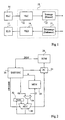
- FIG. 1 schematically shows such a subset 10.
- This subset includes a block 12 of coding to variable length (VLC), or Huffman, providing codes for variable length to a framing block (dithering) 13.
- VLC variable length
- Huffman coding to variable length
- This block 13 delivers a serial bit stream intended to be decoded by a receiving circuit.
- the VLC block generally receives data from coding of strings of zeros (RLC) 14.
- RLC strings of zeros
- Such coding consists to transform a string of zeros followed by a non-zero value in a couple of values, the first of which (“run” or chain) indicates the number of zeros preceding the non-zero value, and the second (“level” or level) provides the non-zero value.
- a receiver circuit also part of the sub-assembly 10, includes a frame processing block (descreening) 15 followed by a variable length decoding block (VLD) 16 for perform reciprocal operations on screening 13 and coding VLC 12.
- VLD variable length decoding block
- VLD 16 decoding is generally followed by decoding of strings of zeros (RLD) 17, reciprocal to PLC coding.
- VLC or Huffman coding involves replacing each chain-level couple by a code whose length (from 2 to 12 bits for standards H.261 and H.263) is lower when the probability of occurrence of the couple is high.
- These length codes variable are looked up in correspondence tables and concatenated to form a sequence of contiguous codes.
- the role of screening circuit 14 is to insert the concatenated codes into frames containing various information, including codes error correctors. These frames are defined by standards H.261 and H.263 or by standards H.221 and H.223 which may be used in conjunction with H.261 and H.263.
- subset 10 The operations of subset 10 are generally wired. Indeed, if we wanted to use a general purpose microprocessor programmed to perform these operations, the computing power would be too large to that the cost of the microprocessor is reasonable. This remains true as part of the H.263 standard where bit streams have a bit rate particularly low (suitable for network telephone lines switched).
- microprocessor to performing the operations of subset 10 would be particularly advantageous because it would allow adaptation particularly easy to vary standards by a simple program modification without having to completely redesign the subset.
- An object of the present invention is to allow the realization of the functions of the flow processing subset bits using a power microprocessor particularly low.
- the present invention provides to use a general purpose microprocessor including operators cables dedicated to specific operations encountered in bit stream processing according to H.261, H.263 standards, H.221, or H.223. These dedicated operators are operated by specific instructions that are added to an instruction set classic. By choosing the operator functions well dedicated, the power of the microprocessor can be made so low that the cost of the resulting subset becomes even lower to that of a purely wired sub-assembly.
- the operations for which we provide a dedicated operator are concatenation variable length codes to provide a sequence of codes contiguous, extracting variable length codes from such sequence, and the calculation of a signature on a sequence of bits.
- the microprocessor will include an operator allowing to perform the three operations, but we will notice that the use of an operator allowing only one of these three operations allow significant gains of computing power.
- a first version microprocessor includes an operator dedicated to a signature calculation on a sequence of bits, the operator being associated with a dedicated instruction using two parameters, the first of which is a word containing a group of bits constituting a successive part of said sequence, and the second parameter of which indicates the length of the group of bits, the operator reacting to the instruction dedicated by updating a signature register with a signature calculated on the content of the signature register and on the group of bits.
- the signature is the remainder of a polynomial division of the sequence of bits by a generator polynomial contained in a polynomial register.
- a second version of microprocessor according to the present invention includes an operator dedicated to a concatenation of variable length codes, to an extraction of codes of variable length, as well as a signature calculation on a bit sequence.
- the present invention provision is made to carry out software way the bit stream processing of a system of compression / decompression of moving images.
- the present invention is based on a study by the applicant which allowed to reveal the operations that would be the most expensive in calculation time if they were to be performed by a microprocessor general purpose. These operations are concatenation variable length codes to provide a sequence of codes contiguous, extracting variable length codes from a contiguous code sequence, and the calculation of a signature on a bit sequence.
- a general purpose microprocessor conventional supplemented by a cable operator performing at least one from these operations to the execution of a dedicated instruction, the microprocessor power is significantly reduced.
- a cable operator dedicated to the three operations mentioned above allows the use of an 8-bit microprocessor clocked at a frequency of 54 MHz. Microprocessor frequency goes down at 3 MHz within the specific framework of standard H.263 (maximum bit rate 30 kbits / s).
- FIG. 2 schematically illustrates a microprocessor classic "Harvard” type.
- This microprocessor includes a ROM memory 20 containing the instructions of the program to be executed, this ROM memory being separated from a memory (ROM or RAM) 22 in which data necessary for the program are stored.
- a program counter (PC) 24 selects in the memory 20 the instruction to execute, this instruction being supplied to an instruction decoder 26.
- This decoder 26 provides a operation code (opcode) which activates one or more operators corresponding cables in an arithmetic and logic unit (ALU) 28.
- opcode operation code
- ALU arithmetic and logic unit
- Various customary work registers, including one accumulator 32, are associated with the ALU unit.
- the decoder 26 provides an address jump to program counter 24, a reading address A or write to memory 22, or immediate data DI to the unit 28.
- the memory 22, the ALU 28, and the accumulator 32 are interconnected by a data bus D.
- a multiplexer 34 allows to select, from the immediate data DI and a data present on bus D, that supplied to the ALU 28 unit. This selection is made by a bit of the operation code opcode.
- ALU 28 has various flags that are raised depending on the results of certain operations. In the case of the execution of a conditional jump, a flag corresponding to the condition is supplied to the program counter 24. Depending on the state of this flag, the address provided by the decoder 26 is loaded or not in program counter 24.
- a microprocessor according to the invention integrates into its arithmetic and logic unit 28, in addition to cable operators for performing the conventional operations of a microprocessor general purpose (addition, multiplication, operations logic, etc.), a wired operator to perform minus one of the three operations mentioned above, specific to bit stream processing in a compression / decompression system images.
- Figures 3A to 3C show three parts of a example of a wired operator to perform the concatenation of variable length or Huffman codes.
- This operator responds to a specific concatenation instruction which will be called "CAT" and which is used with two parameters.
- a first parameter D is a word containing a Huffman code to be concatenated
- the second parameter is a word indicating the length L of the code contained in the first parameter.
- the width of these words will generally be that of the data bus D (for example 8 bits).
- the Huffman code of length not equal to the width of the bus, for example is stored right in the word that contains it.
- the CAT instruction can be used with an address indicating the location in memory 22 of the word containing the Huffman code to be processed.
- the decoder 26 presents this address to memory 22 and provides a code opcode operation which activates an operator to read the memory in unit ALU 28.
- This operation code operates at the same time the operator dedicated to concatenation who operates, as first parameter, the word present on the data bus D and, as a second parameter, a word contained in the accumulator 32, for example.
- the programmer ensures that the length L of the code is charged by any conventional means into the accumulator 32 just before the execution of the CAT instruction.
- the special function of CAT instruction and the associated operator is to concatenate L bits of the first parameter D to bits previously inserted in a specific register "CAT".
- CAT specific register
- the CAT register has enough space to receive the L bits of the code to be concatenated, for example if the parameter D is 0000 0ABC, where ABC are the bits of the code, we want update the CAT register with the value 0123 4ABC, by assuming that the bits of the codes are to be given high weight by head.
- the CAT register does not contain enough place to receive the code, for example if the parameter D is worth OOAB CDEF, we wish to update the CAT register by value 0000 OOEF and transfer to an AUX auxiliary register the value 1234 ABCD. Whenever the auxiliary register is thus updated, it contains a successive sequence of bits belonging to contiguous or concatenated codes.
- the specific CAT register is designated par 40.
- the content of the CAT register is supplied to a left shift of the number of bits indicated by the parameter L.
- a bitwise OR gate 44 receives the output of the offset circuit 42 and word D containing the Huffman code to be concatenated.
- a register (FREE) 46 indicates the free space in the CAT register to receive a new code.
- a subtractor 48 differentiates between the parameter L and the content of the register 46. This difference is supplied to a generator mask 50 and the sign sgn of the difference controls a multiplexer 52. If the sign is negative, indicating that the free space in the CAT register is sufficient to receive the code to be concatenated, the multiplexer 52 chooses the output of gate 44 for update the contents of the CAT register. If the sign is positive, i.e. if the CAT register does not contain enough of space to receive the code to be concatenated, the multiplexer 52 choose the output of an AND gate bit by bit 54 to update the contents of the CAT register. Gate AND 54 receives the word D containing the code to be concatenated and the mask created by the generator mask 50. All the mask bits are zero except a number of least significant bits equal to the difference provided by the subtractor 48.
- the register CAT contains the value 0000 1234
- the word D is 0000 0ABC
- the parameter L is 3
- register 46 indicating the free space in the CAT register, contains the value 4.
- the shift circuit on the left 42 provides the value 0123 4000 which, combined by the OR gate 44 at word D, provides the value 0123 4ABC.
- the multiplexer 52 selects this value for updating the register CAT because the difference between the L parameter and the content of register 46 is negative.
- the word D is worth OOAB CDEF
- the parameter L is worth 6
- the free space, content in register 46 is 4.
- Multiplexer 52 then selects the output of the AND gate 54.
- the mask 50 being 0000 0011, the value by which the CAT register is updated is 0000 OOEF. So the last bits of the code are inserted at the beginning from the CAT register.
- 56 designates the auxiliary register AUX above, in which we transfer the previous content from the CAT register, supplemented by the first bits of the code.
- This AUX register receives the output of an OR gate bit by bit 58.
- a first input of this gate 58 receives the output of a circuit 60 offset to the right of the word D. The amount of offset for this circuit 60 is determined by the difference provided by the subtractor 48.
- a second input from OR gate 58 receives the output a circuit 62 for shifting the content of the CAT register to the left.
- the amount of circuit 62 offset is determined by the contents of register 46.
- the auxiliary register 56 loads the exit from door 58 when the sign of the difference provided by the subtractor 48 is positive.
- the output of the offset circuit 62 is 1234 0000, while the shift circuit output 60 is 0000 ABCD. Leaving the door 58 then provides the expected value 1234 ABCD to the auxiliary register 56.
- FIG. 3C illustrates an example of a circuit allowing to update register 46 so that it indicates the free space in the CAT register at each concatenation (at each execution of the CAT instruction).
- a subtractor 64 provides a first input of a multiplexer 66 the difference between the contents of register 46 and parameter L. This difference is also supplied to an adder 68 which also receives a fixed value w equal to the size of the CAT register (8 in the examples). The output of this adder 68 is supplied to the second input of the multiplexer 66.
- the multiplexer 66 selects, to update the contents of register 46, the output of subtractor 64 if the sign of the difference it provides is positive, and selects the output of adder 68 if the sign is negative.
- CAT instruction is used and combined to conventional instructions is left free to the programmer and is outside the scope of the present invention.
- the programmer must only ensure that the contents of the auxiliary register 56 be read each time it has been renewed. This can be performed in various ways, for example by comparing the current content of the CAT register to the content it had when previous execution of the CAT instruction, or by counting successive lengths L.
- the successive contents of the auxiliary register 56 are for example stored at consecutive addresses in memory 22 to form a succession of contiguous codes.
- variable length coding In the context of variable length coding, the correspondence between each pair of chain-level values and a Huffman code is provided by standard tables stored in a ROM memory which is part of the memory 22.
- the operations searching for a Huffman code in tables can be performed efficiently enough by a series of instructions general purpose. Once the search is complete, the code found and its length are stored at predefined addresses. So, for example, the length is written to accumulator 32 by a classic instruction and we execute immediately after the CAT instruction with the address of the code found.
- the succession of contiguous codes generated from successive contents of auxiliary register 56 is subject to framing operations according to H.221 or H.223 standards. A part of the framing operations is preferably carried out using a dedicated operator described later.
- the length of a code is greater the width of the data bus and the CAT register. In this case, the code is split and the fractions of the code are processed by successive CAT instructions.
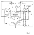
- Figure 4 schematically shows an example cable operator dedicated to extracting Huffman codes from a sequence of contiguous or concatenated codes. This operator responds to a specific instruction which will be called "XTA" and which is used with, as a parameter, the length L of a code to be extracted.
- XTA specific instruction which will be called "XTA" and which is used with, as a parameter, the length L of a code to be extracted.
- the XTA instruction is in fact reciprocal to the CAT instruction.
- the special function of the XTA instruction and the associated operator is to extract L consecutive bits in a specific register XTA 70 immediately after bits previously extracts.
- the XTA register stores a successive part of a code sequence being processed.
- the Missing bits are taken from the start of an AUX auxiliary register.
- the number of bits remaining to be extracted from the XTA register is indicated by a register (RESTE) 74.
- a subtractor 76 delivers the difference between the length L provided by the XTA instruction and the REST content of the register 74 to a first input of a multiplexer 78 and to a control input of a right shift circuit 80.
- a multiplexer 82 updates the contents of the XTA registry by itself when the sign sgn of this difference is positive, and by the content of auxiliary register 72 if this sign is negative.
- the sign sgn also controls a multiplexer 84 which receives on a first input the output of an AND gate bit by bit 86 and on a second input the output of an OR gate bit by bit 88.
- the output of multiplexer 84 provides a word D containing the bits extracts, arranged on the right. If the sign sgn is positive, the multiplexer 84 selects the output of gate 86 for the word D, otherwise the exit from door 88.
- the word D is supplied, for example, on the data bus.
- the XTA instruction is used with a parameter which is the address where the word D.
- the word D can be written in a register, for example accumulator 32, where it will be read by a further instruction.
- the content of the XTA register is provided at the entrance to the shift circuit to the right 80 and to the input of a left shift 90.
- a subtractor 92 supplies as a command at the offset circuit 90 the difference between the length L and the content REMAINS from register 74.
- the outputs of the shift circuits 80 and 90 are supplied respectively to the first entries of gate 86 and of an AND gate bit by bit 94.
- the second inputs of doors 86 and 94 receive the output of a generator mask 96 controlled by the length L.
- the OR gate 88 receives on a first input the output from gate 94 and, on a second input, the output of a circuit 98 right shift.
- This 98 offset circuit receives the content of auxiliary register 72 and is controlled by a subtractor 100 which provides the difference between a fixed value w, corresponding to the size of the XTA register, and the value supplied by subtractor 92.
- the difference provided by the subtractor 100 is also supplied to a second input of multiplexer 78 which puts update the content REMAINING from register 74 by the difference provided by subtractor 76 if this difference is positive, and by the difference provided by the subtractor 100 otherwise.
- circuit 80 shifts to right the contents of the XTA register of 2, and therefore provides the value OOXX ABCD.
- the mask provided by circuit 96 is worth 00001111.
- the output of AND gate 96, transmitted as word D by the multiplexer 84, provides the desired value 0000 ABCD.
- the REST content of register 74 is updated by the value 2 provided by subtractor 76.
- the content of the register XTA remains unchanged, but register 74 indicates that it remains only 2 bits to extract from the XTA register at the next execution of the XTA instruction.
- the code to extract is too long compared to the bits remaining to extract from the XTA register.
- the code is straddling the end of the XTA register and the start of the auxiliary register 72 which contains the value DEXX XXXX.
- the circuit 90 shifts the contents of the XTA register by two bits to the left, and therefore provides the value XXXA BCOO.
- the mask provided by generator 96 is worth 0001 1111, from which it follows that gate AND 94 provides the value 000A BC00.
- Circuit 98 shifts the content from the 6-bit auxiliary register 72 to the right, and provides therefore the value 0000 00DE.
- the exit from OR gate 88 which is selected by multiplexer 84, provides the desired value 000A BCDE for the word D.
- the XTA register is updated by the content of the register auxiliary 72 while register 74 is updated by the value 6 provided by subtractor 100.
- the XTA register receives the value DEXX XXXX, while register 74 indicates that there are 6 bits left to extract from the XTA register at the next execution of the XTA instruction, namely the 6 "X" bits.
- auxiliary register 72 be renewed each time it has been transferred to the XTA registry. This can be done in various ways, for example example by comparing the current contents of the XTA register to content it had during the previous execution of the instruction XTA, or by counting successive lengths L.
- the sequence of bits to be processed is, for example, stored in memory by words to consecutive addresses.
- the sequence the first two words of the sequence are written respectively in the XTA and auxiliary registers 72, while that register 74 is initialized to the value 8 (the size of the XTA register).
- the following words in the sequence will be written successively in the auxiliary register 72 progressively that the content of the XTA register is renewed by transfers automatic successive contents of the auxiliary register 72.
- the length L of a code to be extracted is not known at advance. So, before extracting a code, you have to find its length L, which is done by examining the start of the bit code per bit. Indeed, the first bits of a Huffman code determine the length of the code by reference to the Huffman tables stored in memory 22. More specifically, the tables of Huffman's are organized into subtables hierarchically and each successive bit of the code identifies a level subtable hierarchical lower than the subtable identified by the previous bit. When an unspecified number of first bits has been examined, a specific subtable is identified, which does not contains only codes of the same length. We know the length code at this time. The translation of the code can be found in this table and is identified by the not yet examined bits of the code.
- FIG. 5 represents an example of an operator dedicated to a signature calculation on a sequence of bits, this signature being intended to allow detection and / or correction errors that occurred in the sequence.
- This operator is associated with an instruction which will be called "BCH" which uses two parameters, one being a word D containing a group of bits on which to calculate the signature, and the second being the length L of the group of bits.
- the group of bits to be processed is, for example, stored on the right in the word D.
- Concatenated codes provided by length coding variable are put in frames with a number of bits fixed according to standards H.221, H.261 and H.263. According to standard H.223, the number of bits in the frames is variable.
- a signature called BCH which corresponds to the rest of the division of the polynomial consisting of the bit sequence of the frame by a specific generator polynomial.
- This generator polynomial is of degree 4 for standard H.221, of degree 8 or 15 for the H.223 standard, and of degree 18 for the H.261 and H.263 standards.
- the special function of the BCH instruction and the associated operator is to allow the calculation of a signature BCH by processing a sequence of bits in successive groups of bits- instead of processing it bit by bit, updating the signature for each successive group carried out in a cycle instruction.
- FIG. 5 represents the operator in the particular example of an 8-bit microprocessor in which groups of at most 8 bits D 0 to D 7 can be processed.
- the coefficients of the generator polynomial are contained in a register POLY consisting of flip-flops 152, also 18 in number, numbered from 0 to 17.
- the exclusive OR gates are symbolized by adders because, in the Galois field on which the polynomial calculations are defined, the exclusive OR operations are in fact additions.
- the i-th exclusive OR gate 154 receives the i-th bit of the polynomial generator on its first input and the (i + l) th bit of the BCH signature on its second entry.
- the i-th gate 154 of the j-th row receives, on its first input, the i-th bit of the generator polynomial and, on its second input, the output of the (i + 1) th gate 154 of the previous row .
- the last gate 154 of the j-th row receives, on its first input, the last bit of the generator polynomial and, on its second input, the bit D j-1 of the word D provided as the first parameter by the instruction BCH.
- Each gate 154 is associated with a multiplexer 156 which will be described later.
- the multiplexers 156 are in the position symbolized in the three first rows, connecting doors 154 to each other manner which has just been described.
- the gates 154 of the j-th row supply the signature calculated on the whole of the preceding series and of bits D 0 to D j -1 provided by the current BCH instruction. It then suffices to update the register BCH with the outputs of the doors of the j-th row and to execute the instruction BCH again with a new group of bits to obtain a new signature at the output of the row of doors 154 associated with the number of bits of the new group.
- the example illustrated in Figure 5 is particularly well suited to a generation of the circuit using the VHDL language.
- the i-th multiplexer 156 of the j-th row receives the output of the i-th gate 154 of the same row and the output of the i-th multiplexer from the previous row.
- the i-th multiplexer of the first row receives, instead of the output of a multiplexer, the i-th bit of the BCH signature.
- the second entry of the i-th door 154 of a row, except that of the last door of the row receives the output of the (i + 1) th multiplexer of the row previous.
- the outputs of the last row multiplexers provide the new content of the BCH register.
- the multiplexers of the j-th row are controlled by a common signal EN j-1 supplied by a decoder 158 which receives from the BCH instruction the length L of the group of bits to be processed.
- the decoder 158 which is nothing other than a generator of mask, controls the first L rows of multiplexers (like this is shown for the first three rows) so that they select the gate outputs 154, while the multiplexers remaining are ordered to select the outputs of previous multiplexers. In this case, the desired calculation is carried out by the first L rows of doors 154, the result being transmitted directly to the BCH register by the multiplexers of the remaining rows.
- the BCH instruction associated with its operator, allows calculate a signature both on transmission and on reception.
- the sequence of bits on which the signature is a continuous sequence, stored for example in word memory to consecutive addresses.
- BCH instruction can then be used with the maximum value of L (8 at the figure 5) for each successive word, which makes it possible to process a particularly quickly.
- the parameter L is variable is useful because the length of a bit sequence to be processed is not necessarily a multiple of the width of words. So, at the end of the sequence, we will have to process a number of bits less than the width of a word, stored at right in the word.
- the BCH instruction is also used to perform error calculation.
- a dedicated microprocessor includes all three operators to ensure maximum efficiency. However, if the microprocessor did not understand that one or two of these operators, its effectiveness would present a significant improvement compared to a microprocessor general purpose classic.
- registers of operators are of the same nature as registers conventionally incorporated into an ALU, and are therefore accessible by conventional instructions intended to handle The registers.
Landscapes
- Physics & Mathematics (AREA)
- General Physics & Mathematics (AREA)
- Engineering & Computer Science (AREA)
- Discrete Mathematics (AREA)
- Multimedia (AREA)
- Theoretical Computer Science (AREA)
- Compression, Expansion, Code Conversion, And Decoders (AREA)
Claims (5)
- Ein Mikroprozessor, gekennzeichnet dadurch, daß er einen einer Signaturberechnung über eine Bitsequenz gewidmeten Operator aufweist, wobei die erwähnte Signatur das Ziel hat, eine Detektion und/oder Korrektur von Fehlern, die in der Sequenz auftreten, zu ermöglichen, wobei der Operator mit einem zugewiesenen bzw. gewidmeten Befehl der zwei Parameter verwendet, assoziiert ist, wobei der erste (D) der Parameter ein Wort einschließlich einer Gruppe von Bits ist, die einen sukzessiven bzw. darauffolgenden Teil der Sequenz bilden, und wobei der zweite Parameter (L) die Länge der Gruppe von Bits anzeigt, und wobei der Operator auf den gewidmeten Befehl anspricht, und zwar durch Aktualisieren bzw. auf den neuesten Stand Bringen eines Signaturregisters (BCH) mit einer Signatur berechnet aus bzw. über den Inhalt des Signaturregisters und der Gruppe der Bits.
- Der Mikroprozessor nach Anspruch 1, dadurch gekennzeichnet, daß die Signatur der Rest einer Polynomdivision einer Bitsequenz durch einen Generator polynom ist, und zwar enthalten in einem Polynomregister (POLY).
- Der Mikroprozessor nach Anspruch 2, dadurch gekennzeichnet, daß der gewidmete Operator folgendes aufweist:Exklusive ODER-Gatter (ODER-Schaltungen) (154) angeordnet in w Zeilen und n Spalten, wobei n die Größe des Signaturregisters ist und wobei w die maximale Länge der Gruppe von Bits ist, wobei das i-te Gatter der j-ten Zeile das i-te Bit des Polynomregisters an einem ersten Eingang empfängt, und, an einem zweiten Eingang das (i+1)-te Bit des Signaturregisters, wenn j = 1, das j-te Bit des ersten Parameters (D), wenn i = n, und die Ausgangsgröße des (i+1)-ten Gatters der vorhergehenden Zeile ansonsten; undMittel (156) zur Auswahl der Zeile, deren Rang dem zweiten Parameter (L) entspricht und Transferieren in das Signaturregister (BCH) der Ausgangsgrößen der Gatter der ausgewählten Zeile.
- Der Mikroprozessor nach Anspruch 3, dadurch gekennzeichnet, daß die erwähnten Mittel folgendes aufweisen:für das i-te Gatter (154) der j-ten Zeile einen Multiplexer (156), der die Ausgangsgröße des Gatters an einem ersten Eingang empfängt, und, an einem zweiten Eingang, das i-te Bit des Signaturregisters wenn j = 1, und, die Ausgangsgröße des i-ten Multiplexers der (j-1)-ten Zeile ansonsten, wobei der neue Inhalt des Signaturregisters (BCH) durch die Ausgangsgrößen der Multiplexer der letzten Zeile geliefert werden; undeinen Decoder (158) zum Empfang des zweiten Parameters (L) zum Schalten der Multiplexer (156) einer entsprechenden Anzahl von ersten Zeilen zu ihren ersten Eingängen und zum Schalten der Multiplexer der verbleibenden Zeilen zu ihren zweiten Eingängen.
- Der Mikroprozessor nach einem der Ansprüche 1 bis 4, dadurch gekennzeichnet, daß er weiterhin folgendes aufweist:einen zweiten Operator gewidmet einer Verkettung von Codes mit variabler Länge zur Bildung einer Sequenz von angrenzenden Codes, wobei der zweite Operator assoziiert ist mit einem zweiten gewidmeten Befehl unter Verwendung von zwei Parametern, wobei ein erster (D) derselben ein Wort ist, welches eine Gruppe von Bits enthält, und wobei der zweite (L) von diesen die Länge der Bitgruppe anzeigt, wobei der zweite Operator auf den zweiten gewidmeten Befehl anspricht durch Isolieren oder Trennen in seinem ersten Parameter der Bitgruppe mit der Länge angezeigt durch seinen zweiten Parameter und durch Einsetzen der Bitgruppe, die derart getrennt ist in ein zweites aktives Register (CAT), und zwar in Verkettung mit einer Bitgruppe, die in das aktive Register eingesetzt wurde durch eine vorhergehende Ausführung des zweiten gewidmeten Befehls; undeinen dritten Operator gewidmet einer Extraktion von Codes mit variabler Länge aus einer Sequenz von angrenzenden Codes, wobei der dritte Operator mit einem dritten gewidmeten Befehl assoziiert ist, und zwar unter Verwendung eines Parameters (L), der die Länge einer Gruppe von zu extrahierenden Bits anzeigt, wobei der dritte Operator auf den dritten Befehl anspricht durch Extrahieren aus einem dritten aktiven Register (XTA), der durch seinen Parameter angezeigten Anzahl von Bits, und zwar startend von dem Ende einer Gruppe von Bits, die extrahiert wurde aus dem dritten aktiven Register durch eine vorhergehende Ausführung des dritten gewidmeten Befehls.
Applications Claiming Priority (2)
| Application Number | Priority Date | Filing Date | Title |
|---|---|---|---|
| FR9615913A FR2757288B1 (fr) | 1996-12-17 | 1996-12-17 | Microprocesseur dedie au traitement de flux de bits dans un systeme de compression/decompression d'images animees |
| FR9615913 | 1996-12-17 |
Publications (2)
| Publication Number | Publication Date |
|---|---|
| EP0849708A1 EP0849708A1 (de) | 1998-06-24 |
| EP0849708B1 true EP0849708B1 (de) | 2002-07-10 |
Family
ID=9499050
Family Applications (1)
| Application Number | Title | Priority Date | Filing Date |
|---|---|---|---|
| EP97410142A Expired - Lifetime EP0849708B1 (de) | 1996-12-17 | 1997-12-16 | Digitaler Bildprozessor zur Bewegtbildkompression/-dekompression |
Country Status (4)
| Country | Link |
|---|---|
| US (1) | US6133859A (de) |
| EP (1) | EP0849708B1 (de) |
| DE (1) | DE69713867T2 (de) |
| FR (1) | FR2757288B1 (de) |
Families Citing this family (4)
| Publication number | Priority date | Publication date | Assignee | Title |
|---|---|---|---|---|
| US7596277B2 (en) * | 2002-04-09 | 2009-09-29 | Senthil Govindaswamy | Apparatus and method for detecting error in a digital image |
| JP3772976B2 (ja) * | 2002-05-22 | 2006-05-10 | ソニー株式会社 | プロセッサ、エンコーダ、デコーダ及び電子機器 |
| US6707398B1 (en) * | 2002-10-24 | 2004-03-16 | Apple Computer, Inc. | Methods and apparatuses for packing bitstreams |
| US6707397B1 (en) * | 2002-10-24 | 2004-03-16 | Apple Computer, Inc. | Methods and apparatus for variable length codeword concatenation |
Family Cites Families (6)
| Publication number | Priority date | Publication date | Assignee | Title |
|---|---|---|---|---|
| US4899149A (en) * | 1986-02-28 | 1990-02-06 | Gary Kahan | Method of and apparatus for decoding Huffman or variable-length coees |
| JP2758826B2 (ja) * | 1994-03-02 | 1998-05-28 | 株式会社リコー | 文書検索装置 |
| KR100224815B1 (ko) * | 1995-06-23 | 1999-10-15 | 윤종용 | 데이타 압축 및 신장방법 |
| KR0180164B1 (ko) * | 1995-07-27 | 1999-05-01 | 배순훈 | 가변길이 부호기 |
| US5650905A (en) * | 1995-12-28 | 1997-07-22 | Philips Electronics North America Corporation | Variable length decoder with adaptive acceleration in processing of Huffman encoded bit streams |
| US6054942A (en) * | 1997-08-14 | 2000-04-25 | Cisco Technology, Inc. | System and method for scaleable encoding and decoding of variable bit frames |
-
1996
- 1996-12-17 FR FR9615913A patent/FR2757288B1/fr not_active Expired - Fee Related
-
1997
- 1997-12-15 US US08/991,022 patent/US6133859A/en not_active Expired - Lifetime
- 1997-12-16 DE DE69713867T patent/DE69713867T2/de not_active Expired - Fee Related
- 1997-12-16 EP EP97410142A patent/EP0849708B1/de not_active Expired - Lifetime
Also Published As
| Publication number | Publication date |
|---|---|
| DE69713867D1 (de) | 2002-08-14 |
| EP0849708A1 (de) | 1998-06-24 |
| DE69713867T2 (de) | 2003-03-13 |
| FR2757288A1 (fr) | 1998-06-19 |
| US6133859A (en) | 2000-10-17 |
| FR2757288B1 (fr) | 1999-02-26 |
Similar Documents
| Publication | Publication Date | Title |
|---|---|---|
| EP0142439B1 (de) | Verfahren zur Kompression einer Folge digitaler Informationen und Vorrichtung dafür | |
| EP0154340A1 (de) | Rechner für die Inverse diskrete Cosinus-Transformation | |
| EP0154341B1 (de) | Rechner für die diskrete Cosinus-Transformation | |
| FR2599872A1 (fr) | Dispositifs de calcul de transformees cosinus mono-dimensionnelles, et dispositif de codage et dispositif de decodage d'images comportant de tels dispositifs de calcul | |
| WO2002063776A2 (fr) | Procede de compression/decompression d'un document structure | |
| FR2782592A1 (fr) | Dispositif et procede de compression de donnees d'images recues a partir d'un capteur d'images a configuration bayer, et systeme utilisant ce dispositif | |
| WO2010037570A1 (fr) | Dispositif de traitement en parallele d'un flux de donnees | |
| FR2588142A1 (fr) | Systeme permettant le traitement a haute vitesse par convolutions de donnees d'image. | |
| FR2605818A1 (fr) | Codeur-decodeur algebrique de codes en blocs reed solomon et bch, applicable aux telecommunications numeriques | |
| EP0849709B1 (de) | Digitaler Bildprozessor zur Bewegtbildkompression/-dekompression | |
| EP0849708B1 (de) | Digitaler Bildprozessor zur Bewegtbildkompression/-dekompression | |
| WO1989010042A1 (fr) | Procede de codage et de decodage d'informations, par blocs, et dispositifs de codage et de decodage, pour la mise en oeuvre de ce procede | |
| FR2823050A1 (fr) | Dispositif implementant conjointement un post-traitement et un decodage de donnees | |
| EP0476592A2 (de) | Adressengenerator für den Datenspeicher eines Prozessors | |
| FR2773284A1 (fr) | Circuit de calcul de polynome de syndrome et un circuit de decodage reed-solomon | |
| EP1972061B1 (de) | Codierungsverfahren des cabac-typs | |
| EP0376384A1 (de) | Informationsübermittlungseinrichtung unter Verwendung von statistischer Kodierung, Sende- und Empfangsteil für eine solche Anordnung | |
| FR2543384A1 (fr) | Procede de codage adaptatif, et de decodage, d'une image de television, et dispositifs pour la mise en oeuvre de ce procede | |
| EP0911760B1 (de) | Verfahren und Vorrichtung zur iterativen Bildtransformation und -dekodierung | |
| FR2475763A1 (fr) | Processeur numerique a structure pipeline | |
| FR2757973A1 (fr) | Processeur de traitement matriciel | |
| FR2544524A1 (fr) | Processeur de signaux numeriques et multicalculateur | |
| EP1322117A1 (de) | Arithmetischer Kodierer und Dekodierer | |
| EP0241352A1 (de) | Schaltung zur linearen Transformationsausführung auf einem digitalen Signal | |
| FR3161778A1 (fr) | Réseau de neurones binaires |
Legal Events
| Date | Code | Title | Description |
|---|---|---|---|
| PUAI | Public reference made under article 153(3) epc to a published international application that has entered the european phase |
Free format text: ORIGINAL CODE: 0009012 |
|
| AK | Designated contracting states |
Kind code of ref document: A1 Designated state(s): DE FR GB IT |
|
| AX | Request for extension of the european patent |
Free format text: AL;LT;LV;MK;RO;SI |
|
| RAP3 | Party data changed (applicant data changed or rights of an application transferred) |
Owner name: STMICROELECTRONICS S.A. |
|
| 17P | Request for examination filed |
Effective date: 19981219 |
|
| AKX | Designation fees paid |
Free format text: DE FR GB IT |
|
| RBV | Designated contracting states (corrected) |
Designated state(s): DE FR GB IT |
|
| GRAG | Despatch of communication of intention to grant |
Free format text: ORIGINAL CODE: EPIDOS AGRA |
|
| 17Q | First examination report despatched |
Effective date: 20010904 |
|
| RAP1 | Party data changed (applicant data changed or rights of an application transferred) |
Owner name: STMICROELECTRONICS S.A. |
|
| GRAG | Despatch of communication of intention to grant |
Free format text: ORIGINAL CODE: EPIDOS AGRA |
|
| GRAH | Despatch of communication of intention to grant a patent |
Free format text: ORIGINAL CODE: EPIDOS IGRA |
|
| GRAH | Despatch of communication of intention to grant a patent |
Free format text: ORIGINAL CODE: EPIDOS IGRA |
|
| GRAA | (expected) grant |
Free format text: ORIGINAL CODE: 0009210 |
|
| AK | Designated contracting states |
Kind code of ref document: B1 Designated state(s): DE FR GB IT |
|
| PG25 | Lapsed in a contracting state [announced via postgrant information from national office to epo] |
Ref country code: IT Free format text: LAPSE BECAUSE OF FAILURE TO SUBMIT A TRANSLATION OF THE DESCRIPTION OR TO PAY THE FEE WITHIN THE PRESCRIBED TIME-LIMIT;WARNING: LAPSES OF ITALIAN PATENTS WITH EFFECTIVE DATE BEFORE 2007 MAY HAVE OCCURRED AT ANY TIME BEFORE 2007. THE CORRECT EFFECTIVE DATE MAY BE DIFFERENT FROM THE ONE RECORDED. Effective date: 20020710 |
|
| REG | Reference to a national code |
Ref country code: GB Ref legal event code: FG4D Free format text: NOT ENGLISH |
|
| REF | Corresponds to: |
Ref document number: 69713867 Country of ref document: DE Date of ref document: 20020814 |
|
| GBT | Gb: translation of ep patent filed (gb section 77(6)(a)/1977) |
Effective date: 20021010 |
|
| PLBE | No opposition filed within time limit |
Free format text: ORIGINAL CODE: 0009261 |
|
| STAA | Information on the status of an ep patent application or granted ep patent |
Free format text: STATUS: NO OPPOSITION FILED WITHIN TIME LIMIT |
|
| 26N | No opposition filed |
Effective date: 20030411 |
|
| PGFP | Annual fee paid to national office [announced via postgrant information from national office to epo] |
Ref country code: FR Payment date: 20051208 Year of fee payment: 9 |
|
| PGFP | Annual fee paid to national office [announced via postgrant information from national office to epo] |
Ref country code: DE Payment date: 20051209 Year of fee payment: 9 |
|
| PGFP | Annual fee paid to national office [announced via postgrant information from national office to epo] |
Ref country code: GB Payment date: 20051214 Year of fee payment: 9 |
|
| PG25 | Lapsed in a contracting state [announced via postgrant information from national office to epo] |
Ref country code: DE Free format text: LAPSE BECAUSE OF NON-PAYMENT OF DUE FEES Effective date: 20070703 |
|
| GBPC | Gb: european patent ceased through non-payment of renewal fee |
Effective date: 20061216 |
|
| REG | Reference to a national code |
Ref country code: FR Ref legal event code: ST Effective date: 20070831 |
|
| PG25 | Lapsed in a contracting state [announced via postgrant information from national office to epo] |
Ref country code: GB Free format text: LAPSE BECAUSE OF NON-PAYMENT OF DUE FEES Effective date: 20061216 |
|
| PG25 | Lapsed in a contracting state [announced via postgrant information from national office to epo] |
Ref country code: FR Free format text: LAPSE BECAUSE OF NON-PAYMENT OF DUE FEES Effective date: 20070102 |