EP0849770B1 - Verfahren zur Herstellung von helikal gewickelten Wendelkörpern - Google Patents
Verfahren zur Herstellung von helikal gewickelten Wendelkörpern Download PDFInfo
- Publication number
- EP0849770B1 EP0849770B1 EP97121787A EP97121787A EP0849770B1 EP 0849770 B1 EP0849770 B1 EP 0849770B1 EP 97121787 A EP97121787 A EP 97121787A EP 97121787 A EP97121787 A EP 97121787A EP 0849770 B1 EP0849770 B1 EP 0849770B1
- Authority
- EP
- European Patent Office
- Prior art keywords
- core
- wire
- winding wire
- winding
- coil
- Prior art date
- Legal status (The legal status is an assumption and is not a legal conclusion. Google has not performed a legal analysis and makes no representation as to the accuracy of the status listed.)
- Expired - Lifetime
Links
Images


Classifications
-
- B—PERFORMING OPERATIONS; TRANSPORTING
- B21—MECHANICAL METAL-WORKING WITHOUT ESSENTIALLY REMOVING MATERIAL; PUNCHING METAL
- B21F—WORKING OR PROCESSING OF METAL WIRE
- B21F35/00—Making springs from wire
- B21F35/006—Double-twist coil springs
-
- H—ELECTRICITY
- H01—ELECTRIC ELEMENTS
- H01K—ELECTRIC INCANDESCENT LAMPS
- H01K1/00—Details
- H01K1/02—Incandescent bodies
-
- H—ELECTRICITY
- H01—ELECTRIC ELEMENTS
- H01K—ELECTRIC INCANDESCENT LAMPS
- H01K3/00—Apparatus or processes adapted to the manufacture, installing, removal, or maintenance of incandescent lamps or parts thereof
- H01K3/02—Manufacture of incandescent bodies
Definitions
- the invention relates to methods for producing helically wound spiral bodies according to the preamble of claim 1 or claim 2.
- Es are either incandescent in the sense of simple or also double coiled filament for incandescent lamps according to the generic term of claim 1 or for coils for pin electrodes of high-pressure discharge lamps according to the preamble of claim 2.
- EP-A 149 282 already discloses a process for producing helically wound Incandescent known.
- the filament (coil) is then wound onto the core wire heated to approx. 1900 to 2200 ° C to reduce tensions, for example by means of laser, high frequency or resistance heating of the core wire.
- the glow wire is held on the core wire.
- This cumbersome Procedure is necessary because of the inside diameter of the coil is adapted to the outside diameter of the cored wire and therefore not too avoid that the coil sticks to the core wire.
- a similar process involving heat treatment of the filament for removal the voltages and then triggering the core wire the spiral is also known from DE-OS 34 35 323 and JP-OS 49-67 481.
- the latter used as a means of heating the coil to a temperature a lamp between 600 and 900 ° C.
- a method according to the invention for producing helically wound incandescent bodies uses the technique which is known per se, in which a glow wire made of high-melting material, usually tungsten, is wound onto a core wire and is thermally treated, and is then separated and the core wire is detached.
- a glow wire made of high-melting material usually tungsten
- the new process is based on the idea of winding wire material to influence thermally already during the winding process. Across from conventional methods, in which you also put the filament on one Endloskem winds, you save the subsequent operation of the Relaxation annealing on the core wire in the pulling process. In particular it must be ensured that the radius of curvature of the Coil on which the glow wire subsequently acts after exposure to temperature is wound, is small compared to the axial length of those to be produced from it Mantles. In a particularly preferred embodiment the spiral is separated immediately after winding, so that on a winding can be dispensed with.
- the winding material is additional through the winding process elastic deformation up to the yield point of the wrapping material forced the so-called torsional stress.
- the first method step according to the invention is that the filament is thermally treated.
- the filament In the case of the manufacture of incandescent bodies, the filament must be on a Temperature brought close to the recrystallization temperature of the material become. A temperature in the range between is preferably suitable for this 60 and 90% of the recrystallization temperature. In the case of tungsten this means that the filament reaches a temperature of more than 1200 ° C, preferably more than 1400 ° C is brought. The recrystallization temperature the tungsten is around 1800 C.
- the heated filament is used in both embodiments or coil body wound on the core.
- a noticeable cooling to prevent the spiral produced in this way from heating up of the spiral takes place close to the core.
- Core here includes both core wires and solid core pins.
- the spiral is still hot, but has already cooled slightly sporadically. If the spiral is still too hot before separating, it runs it is colored or oxidation can occur. In the worst case the spiral opens too little or not at all. It also hangs the so-called life of the core.
- the finished spiral has the Separate a residual voltage that occurs immediately after the separation translates into an increase in the inside diameter of the helix, so that the coil loses intimate contact with the core wire. It is sitting only loosely on the core wire.
- the thermal treatment is preferably carried out for both embodiments the winding wire by means of a plasma torch.
- a plasma torch The principle of such Plasma torches are described in more detail, for example, in NL-A 71 12 767.
- Plasma can be, for example, argon, helium, hydrogen, nitrogen and use their mixtures.
- the plasma is burnt in the free gas stream, in particular argon, an argon / nitrogen mixture or an argon / hydrogen mixture is used becomes.
- nitrogen can also be used as a protective gas cone become.
- Both the anode and the cathode are advantageously located of the plasma torch in the burner housing.
- the filament should advantageously have a temperature of more before winding reach than 1200 ° C.
- An interchangeable core is particularly well suited for the production of the glow wire (Machine core) as the core, since this stabilizes the winding process and Tolerances in the winding process minimized. It is recommended that the machine core made of thermally resilient (in the temperature range around 1800 ° C) Material such as Spring steel or tungsten. The machine core should tolerate temperatures up to more than 1800 ° C.
- the material of the winding wire is typical Tungsten, possibly with additives such as potassium, silicon, aluminum and / or thorium can be doped.
- the new method of the first embodiment is used in manufacturing achieved by incandescent bodies that by the winding process in the Helix introduced tension due to the previously made thermal treatment is influenced so that the spiral after able to separate due to the stored mechanical energy is to jump open radially.
- the radial jump is exactly that above described elastic residual stress component. Because of this, this resolves Spiral automatically from the core wire, in contrast to the prior art, where this step is the biggest problem.
- the surprising property that the spiral is particularly advantageous remains almost dimensionally stable in the axial direction.
- the axial opening is analog to turn a spring also elastic and is reflected in the reduction of the wound turns in compliance with the given Winding length.
- the small axial is expressed Residual voltage in that they have only a slight spread of Total length of the helically wound filament causes.
- the temperature during the thermal pretreatment is the first Embodiment just chosen so that the desired final The inner diameter of the helix automatically due to the radial opening after separating.
- the exact one depends on the specific individual case Dimensioning essentially of the diameter of the core and winding material, on the temperature and also on the winding speed.
- the increase in the inside diameter of the spiral caused by radial opening is type-specific and moves in one area from 2 to 30%.
- the desired dimensions can be of the spiral with a compared to the prior art achieve smaller core wire.
- the procedure In the case of the double-coiled filament, the procedure must be modified by using a conventionally made endless primary helix, that is still wound on a core wire, as core wire is used for a secondary helix. The procedure described above is then used to make the secondary helix. After that Then the further processing steps or the triggering directly of the primary nucleus.
- the method is suitable for all known diameters of the core wire or glow wire and is applicable to all known gradients.
- Diameter of the glow wire and core wire is due increasing surface adhesion a tendency to glue the glow wire observed with the core wire.
- This so-called revolver technique enables a longer period of use (Service life) of a machine core.
- Revolver technology means one automatic feeding of a material before the n + 1-th process step, however after completion of the previous nth process step. With a revolver, this corresponds to the automatic feeding of the next one Cartridge chamber and contents after firing a shot.
- a second area of application is pin electrodes for discharge lamps with spirals attached.
- Such electrodes are made of, for example US-A 3 067 357 known.
- such electrodes can be produced by particularly high in the thermal heat treatment of the winding wire Temperatures in the range of the recrystallization temperature used Materials are used. In the case of tungsten temperatures preferably around or just above 1800 ° C. This will the elastic residual tensions which cause the helix to spring open, prevented. In this way, the winding wire on the core pin or "Burn" the electrode shaft.
- the impressed tensions are nothing more than one forced minimal change in the crystal lattice of a grain or Crystallites that also differ in bond lengths, angles and bond forces reflect. Smeared with every temperature increase of a material the position of the atoms in the crystal lattice more, i.e. their location will be for a special structure is becoming ever more unfavorable in energy terms and even a reversible one Phase transformation (e.g. conversion of the ⁇ phase of a crystal into the ⁇ phase), being above a certain temperature for the prevailing Taken a different, energetically more favorable structure becomes. The sum of the microscopic lattice distortions gives the macroscopic Residual stresses.
- the press fit is the reverse of the winding technique of incandescent bodies. This is because an elastic electrode coil becomes retrofitted provided with a core pin, the outer diameter of which is larger than the inside diameter of the electrode coil. The electrode coil is expanded. The elastic deformation generated by the Feeding the pen a resilient force. Thus the pen is by means of Friction of the individual turns recorded.
- the coil is normally slid on and then welded to the core pin or the core pin is added later inserted into the helix (press fit).
- the process does not require welding or pressing, since the Helps hold the core well on its own.
- one is Damage to the electrode (embrittlement), as occurs during the welding process unavoidable would no longer be possible.
- a displaceable machine core 1 made of spring steel is on one End in a holder 2a and at the other end in a counter holder 2b guided by means of a radial forming and clamping device 15. It can be withdrawn or pushed out in the holder 2a become.
- a stationary machine core can also be used and a moving wire feed unit can be used.
- a glow wire 3 is coming as a winding material from a supply coil 6, whose axis 8 is arranged parallel to the machine core 1, by means of a wire feed (not shown) on the machine core 1 to one Coil 13 wound in compliance with a predetermined slope, the is set by means of a pitch drive 9.
- a section of the glow wire 3 hits the machine core 1, it is thermally treated by means of a plasma torch 4.
- the plasma heating takes place in the free gas stream by means of an argon plasma 5
- Plasma torch is only in operation, while a winding drive 12 and Incline drive 9 are active. If the intended length of a filament is wound, a wire cutter 7 comes into action and lengthens the Illuminant off. The coil jumps up and can be easily stripped off, while the machine core 1 is retracted. Immidiatly after the wire feeder starts again and the plasma torch enters again Action.
- a suitable machine control with appropriate drives ensures the combination of winding process and at the same time thermal treatment of the winding material depending on the speed.
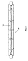
- a simply coiled filament 10 for festoon lamps 20 (Halogen incandescent lamps) with four luminous segments (each about 70 narrow Turns) and three interruptions (five each wide turns) and two ends (eight wide turns each).
- the machine core consists of spring steel with a diameter of 1.4 mm.
- the total clamping length is more than 50 mm.
- the diameter of the filament is about 120 microns.
- Fig. 3 shows schematically a double-coiled filament 11, the Secondary helix is produced by the method according to the invention.
- the filament consists of tungsten.
- an electrode 14 which consists of a core pin or electrode shaft 18 and a coil 19 wound thereon.
- the spiral 19 is burned onto the core pin 18.
Landscapes
- Engineering & Computer Science (AREA)
- Mechanical Engineering (AREA)
- Manufacturing & Machinery (AREA)
- Wire Processing (AREA)
- Resistance Heating (AREA)
- Discharge Lamp (AREA)
- Yarns And Mechanical Finishing Of Yarns Or Ropes (AREA)
- Ropes Or Cables (AREA)
Description
- Figur 1
- eine schematische Darstellung des Wickelvorgangs;
- Figur 2
- eine Halogenglühlampe mit einfach gewendeltem Glühkörper;
- Figur 3
- ein zweifach gewendelter Glühkörper für Glühlampen;
- Figur 4
- eine Stiftelektrode mit aufgebrannter Wendel.
Claims (9)
- Verfahren zur Herstellung helikal gewundener Leuchtkörper für eine Glühlampe, bei dem ein für die spätere Verwendung als Glühdraht geeigneter Wickeldraht (3) aus hochschmelzendem Material auf einen Kern, der aus einem Kerndraht oder Maschinenkern (1) gebildet ist, gewickelt wird und thermisch behandelt wird sowie evtl. anschließend vereinzelt wird und der Kern herausgelöst wird, dadurch gekennzeichnet,a) dass ein Teilstück des Wickeldrahts (3) zunächst thermisch behandelt wird, wodurch dieses Teilstück auf Temperaturen unterhalb der Rekristallisationstemperatur des verwendeten Materials gebracht wird, und zwar zwischen 60 und 90 % dieser Rekristallisationstemperatur,b) daß der Wickeldraht (3) unmittelbar danach auf den Kern (1) gewickelt wird;c) daß der Wickeldraht anschließend zu einem Glühdraht vereinzelt wird, wobei das fertige Gewendel beim Vereinzeln noch eine Restspannung besitzt, die sich unmittelbar nach dem Vereinzeln in eine Vergrößerung des Innendurchmessers des Gewendels umsetzt, so daß das Gewendel den innigen Kontakt zum Kern verliert,d) und daß schließlich der Kern aus dem locker aufsitzenden Gewendel herausgelöst wird.
- Verfahren zur Herstellung helikal gewundener Wendelkörper für eine Entladungslampe, bei dem ein Wickeldraht (3) aus hochschmelzendem Material, der eine Wendel für die Elektrode einer Entladungslampe bildet, auf einen Kern, der ein Kernstift bzw. Elektrodenschaft ist, gewickelt wird und thermisch behandelt wird, dadurch gekennzeichnet,a) dass ein Teilstück des Wickeldrahts (3) zunächst thermisch behandelt wird, wodurch dieses Teilstück auf Temperaturen um oder knapp oberhalb der Rekristallisationstemperatur des verwendeten Materials gebracht wird,b) daß der Wickeldraht (3) unmittelbar danach auf den Kern (1) gewickelt wird.
- Verfahren nach Anspruch oder 2, dadurch gekennzeichnet, daß die thermische Behandlung mittels eines Plasmabrenners (4) erfolgt.
- Verfahren nach Anspruch 3, dadurch gekennzeichnet, daß das Plasmabrennen im freien Gasstrom (5) erfolgt, wobei insbesondere ein Argon /Stickstoff-Gemisch oder ein Argon/Wasserstoffgemisch angewendet wird.
- Verfahren nach Anspruch 1, dadurch gekennzeichnet, daß der Kern ein wechselbarer Maschinenkern ist.
- Verfahren nach Anspruch 5, dadurch gekennzeichnet, daß der Maschinenkern aus thermisch hochbelastbarem Material besteht.
- Verfahren nach Anspruch 5, dadurch gekennzeichnet, daß das Herauslösen des Kerndrahts durch Zurückziehen des Maschinenkerns erfolgt.
- Verfahren nach Anspruch 2, dadurch gekennzeichnet, daß beim Verfahrensschritt a) der Wickeldraht auf Temperaturen in der Nähe des Solidus-Liquidus-Übergangs gebracht wird.
- Verfahren nach Anspruch 1 oder 2, dadurch gekennzeichnet, daß das Material des Wickeldrahts Wolfram ist.
Applications Claiming Priority (3)
| Application Number | Priority Date | Filing Date | Title |
|---|---|---|---|
| DE19653572A DE19653572A1 (de) | 1996-12-20 | 1996-12-20 | Verfahren zur Herstellung von helikal gewickelten Wendelkörpern und Wendelkörper, die nach dieser Methode hergestellt sind |
| DE19653572 | 1996-12-20 | ||
| CA002233854A CA2233854A1 (en) | 1996-12-20 | 1998-04-02 | Method for producing helically wound filament elements, and filament elements produced according to this method |
Publications (3)
| Publication Number | Publication Date |
|---|---|
| EP0849770A2 EP0849770A2 (de) | 1998-06-24 |
| EP0849770A3 EP0849770A3 (de) | 1999-06-09 |
| EP0849770B1 true EP0849770B1 (de) | 2003-10-08 |
Family
ID=31496458
Family Applications (1)
| Application Number | Title | Priority Date | Filing Date |
|---|---|---|---|
| EP97121787A Expired - Lifetime EP0849770B1 (de) | 1996-12-20 | 1997-12-10 | Verfahren zur Herstellung von helikal gewickelten Wendelkörpern |
Country Status (6)
| Country | Link |
|---|---|
| US (1) | US6161598A (de) |
| EP (1) | EP0849770B1 (de) |
| JP (1) | JPH10188918A (de) |
| CN (1) | CN1118861C (de) |
| CA (1) | CA2233854A1 (de) |
| DE (2) | DE19653572A1 (de) |
Families Citing this family (16)
| Publication number | Priority date | Publication date | Assignee | Title |
|---|---|---|---|---|
| US6669523B1 (en) * | 2000-08-23 | 2003-12-30 | General Electric Company | Method of dimensionally stabilizing a tungsten filament |
| KR101166236B1 (ko) * | 2004-04-21 | 2012-07-17 | 코닌클리즈케 필립스 일렉트로닉스 엔.브이. | 산화 토륨이 없는 고압 방전 램프용 텅스텐 전극의 열 처리 방법 |
| CN100452278C (zh) * | 2006-01-23 | 2009-01-14 | 上海轻工业研究所有限公司 | 双轴绕丝机的卷绕部件夹紧处理装置 |
| DE102007034227A1 (de) * | 2007-07-23 | 2009-01-29 | Osram Gesellschaft mit beschränkter Haftung | Verfahren und Vorrichtung zum Herstellen eines Behälters zur Aufnahme einer Hg-Quelle für eine Entladungslampe |
| JP5611589B2 (ja) * | 2007-07-24 | 2014-10-22 | 株式会社東芝 | マグネトロン用フィラメントカソード部材の製造方法およびマグネトロン用フィラメントカソード部材 |
| CN101719460B (zh) * | 2008-10-09 | 2011-12-07 | 上海轻工业研究所有限公司 | 在绕丝机上对灯丝定形的方法 |
| CN103295856B (zh) * | 2012-02-23 | 2016-01-06 | 上海亚尔光源有限公司 | 超高性能点光源电极的成型方法 |
| CN107262633B (zh) * | 2015-11-12 | 2018-10-19 | 中山市衍海贸易有限公司 | 一种安全环保的无芯绕丝机 |
| WO2019117984A2 (en) | 2017-12-14 | 2019-06-20 | Axon Enterprise, Inc. | Systems and methods for an electrode for a conducted electrical weapon |
| CN108787959A (zh) * | 2018-06-08 | 2018-11-13 | 周莉 | 一种加工可调电极用微型弹簧的设备 |
| CN108817286A (zh) * | 2018-06-08 | 2018-11-16 | 周莉 | 一种微型扭转弹簧的加工设备及其制备方法 |
| JP2020061296A (ja) * | 2018-10-11 | 2020-04-16 | ウシオ電機株式会社 | 加熱ランプ |
| CN113084341B (zh) * | 2019-12-19 | 2024-07-16 | 先健科技(深圳)有限公司 | 导丝、焊接装置及焊接方法 |
| KR20210095059A (ko) * | 2020-01-21 | 2021-07-30 | 에이에스엠 아이피 홀딩 비.브이. | 불균일한 열 출력의 필라멘트 램프를 갖는 반도체 처리 챔버 |
| KR20240047985A (ko) | 2021-07-27 | 2024-04-12 | 액손 엔터프라이즈 인코포레이티드 | 전도성 전기 무기용 카트리지 및 전극 |
| KR20250054067A (ko) | 2022-07-28 | 2025-04-22 | 액손 엔터프라이즈 인코포레이티드 | 전도성 전기 무기용 전극 |
Family Cites Families (16)
| Publication number | Priority date | Publication date | Assignee | Title |
|---|---|---|---|---|
| US1057088A (en) * | 1912-06-15 | 1913-03-25 | Gen Electric | Shaping filaments. |
| BE367693A (de) * | 1924-03-15 | |||
| NL19275C (de) * | 1925-09-21 | |||
| GB441207A (en) * | 1934-07-18 | 1936-01-15 | Gen Electric Co Ltd | Improvements in the manufacture of coiled coil filaments for electric incandescent lamps |
| BE413156A (de) * | 1935-01-07 | |||
| US2136649A (en) * | 1936-03-17 | 1938-11-15 | Westinghouse Electric & Mfg Co | Coiled coil and the method and apparatus for making |
| GB481964A (en) * | 1936-08-17 | 1938-03-17 | Allg Glueblampenfabriks Aktien | Filaments for electric incandescent lamps and method of manufacturing the same |
| US2371205A (en) * | 1943-10-30 | 1945-03-13 | Coiled | |
| US2667204A (en) * | 1952-03-29 | 1954-01-26 | Westinghouse Electric Corp | Coiling head assembly |
| NL269416A (de) * | 1960-09-21 | |||
| JPS5374353A (en) * | 1976-12-14 | 1978-07-01 | Nec Corp | Manufacturing device for electron tube helix |
| JPS54144782A (en) * | 1978-04-29 | 1979-11-12 | Toshiba Corp | Method of fabricating tungsten filament |
| US4616682A (en) * | 1984-01-13 | 1986-10-14 | U.S. Philips Corporation | Method of manufacturing helically wound filaments and filaments manufactured by means of this method |
| JPH04303556A (ja) * | 1991-03-30 | 1992-10-27 | Toshiba Lighting & Technol Corp | フィラメントの成形方法 |
| JP2877238B2 (ja) * | 1991-07-05 | 1999-03-31 | 松下電子工業株式会社 | 管球用フィラメントコイルの製造方法 |
| US5680003A (en) * | 1995-05-19 | 1997-10-21 | General Electric Company | Coiled-coil filament design for an incandescent lamp |
-
1996
- 1996-12-20 DE DE19653572A patent/DE19653572A1/de not_active Withdrawn
-
1997
- 1997-12-10 DE DE59710832T patent/DE59710832D1/de not_active Expired - Lifetime
- 1997-12-10 EP EP97121787A patent/EP0849770B1/de not_active Expired - Lifetime
- 1997-12-17 JP JP9364006A patent/JPH10188918A/ja active Pending
- 1997-12-19 CN CN97125574A patent/CN1118861C/zh not_active Expired - Fee Related
-
1998
- 1998-03-31 US US09/052,701 patent/US6161598A/en not_active Expired - Lifetime
- 1998-04-02 CA CA002233854A patent/CA2233854A1/en not_active Abandoned
Also Published As
| Publication number | Publication date |
|---|---|
| CN1118861C (zh) | 2003-08-20 |
| CN1185650A (zh) | 1998-06-24 |
| EP0849770A2 (de) | 1998-06-24 |
| US6161598A (en) | 2000-12-19 |
| CA2233854A1 (en) | 1999-10-02 |
| DE59710832D1 (de) | 2003-11-13 |
| EP0849770A3 (de) | 1999-06-09 |
| JPH10188918A (ja) | 1998-07-21 |
| DE19653572A1 (de) | 1998-06-25 |
Similar Documents
| Publication | Publication Date | Title |
|---|---|---|
| EP0849770A2 (de) | Verfahren zur Herstellung von helikal gewickelten Wendelkörpern und Wendelkörper, die nach dieser Methode hergestellt sind | |
| DE69310823T2 (de) | Hochdruckentladungslampe mit einer Anode mit verbessertem thermischen Verhalten und Verfahren zur deren Herstellung | |
| DE2654715C2 (de) | Hochdruckentladungslampe | |
| EP0391283B1 (de) | Zweiseitig gesockelte Hochdruckentladungslampe | |
| EP0703600B1 (de) | Hochdruckentladungslampe | |
| EP0839381B1 (de) | Reflektorlampe | |
| DE19812298A1 (de) | Metall-Halogenlampe und Verfahren zur Herstellung derselben | |
| EP3909121B1 (de) | Verfahren und vorrichtung zum mehrlagigen einfügen einer spulenmatte in ein bauteil einer elektrischen maschine | |
| EP0560966A1 (de) | Glühkerze | |
| DE602005003240T2 (de) | Hochumformbarer und Hochwarmfestiger Wolframdraht sowie Verfahren zur dessen Herstellung | |
| DE2755213C2 (de) | Nichtabschmelzende Elektrode und Verfahren zu ihrer Herstellung | |
| EP1730766B1 (de) | Elektrodensystem für eine hochdruckentladungslampe | |
| DE69618376T2 (de) | Doppelglühwendel für Glühlampe | |
| EP0446458B1 (de) | Zweiseitig gequetschte Halogenglühlampe | |
| DE69231150T2 (de) | Verfahren zum montieren von faeden in roehrenformigen gluehlampen | |
| US4616682A (en) | Method of manufacturing helically wound filaments and filaments manufactured by means of this method | |
| EP0413147A2 (de) | Glühstiftkerze | |
| EP0255638B1 (de) | Elektrische Glühlampe und Herstellung von deren Röhrenkolben | |
| EP2013896A2 (de) | Halogenglühlampe mit carbidhaltigem leuchtkörper | |
| DE69317726T2 (de) | Röhrenförmige Glühlampe | |
| DE838797C (de) | Kathode fuer elektrische Entladungsvorrichtungen | |
| DE961123C (de) | Elektrische Hochdruckentladungslampe | |
| WO2003079503A1 (de) | Kommutator und verfahren zu seiner herstellung | |
| DE3124261A1 (de) | "elektrische gluehlampe" | |
| DE102011006620A1 (de) | Verfahren zum Herstellen einer Wicklung zur Herstellung von Elektroden für Entladungslampen, Wicklung zur Herstellung von Elektroden für Entladungslampen sowie Verfahren zur Herstellung einer Elektrode für Entladungslampen |
Legal Events
| Date | Code | Title | Description |
|---|---|---|---|
| PUAI | Public reference made under article 153(3) epc to a published international application that has entered the european phase |
Free format text: ORIGINAL CODE: 0009012 |
|
| AK | Designated contracting states |
Kind code of ref document: A2 Designated state(s): BE DE FR GB IT NL |
|
| AX | Request for extension of the european patent |
Free format text: AL;LT;LV;MK;RO;SI |
|
| PUAL | Search report despatched |
Free format text: ORIGINAL CODE: 0009013 |
|
| AK | Designated contracting states |
Kind code of ref document: A3 Designated state(s): AT BE CH DE DK ES FI FR GB GR IE IT LI LU MC NL PT SE |
|
| AX | Request for extension of the european patent |
Free format text: AL;LT;LV;MK;RO;SI |
|
| RIC1 | Information provided on ipc code assigned before grant |
Free format text: 6H 01K 3/02 A, 6H 01K 1/02 B, 6H 01J 9/02 B |
|
| 17P | Request for examination filed |
Effective date: 19990706 |
|
| AKX | Designation fees paid |
Free format text: BE DE FR GB IT NL |
|
| 17Q | First examination report despatched |
Effective date: 20021105 |
|
| GRAH | Despatch of communication of intention to grant a patent |
Free format text: ORIGINAL CODE: EPIDOS IGRA |
|
| RTI1 | Title (correction) |
Free format text: MANUFACTURING PROCEDURE OF HELICOIDALLY WOUND COILED FILAMENTS |
|
| GRAS | Grant fee paid |
Free format text: ORIGINAL CODE: EPIDOSNIGR3 |
|
| GRAA | (expected) grant |
Free format text: ORIGINAL CODE: 0009210 |
|
| AK | Designated contracting states |
Kind code of ref document: B1 Designated state(s): BE DE FR GB IT NL |
|
| REG | Reference to a national code |
Ref country code: GB Ref legal event code: FG4D Free format text: NOT ENGLISH |
|
| REF | Corresponds to: |
Ref document number: 59710832 Country of ref document: DE Date of ref document: 20031113 Kind code of ref document: P |
|
| GBT | Gb: translation of ep patent filed (gb section 77(6)(a)/1977) |
Effective date: 20031224 |
|
| ET | Fr: translation filed | ||
| PLBE | No opposition filed within time limit |
Free format text: ORIGINAL CODE: 0009261 |
|
| STAA | Information on the status of an ep patent application or granted ep patent |
Free format text: STATUS: NO OPPOSITION FILED WITHIN TIME LIMIT |
|
| 26N | No opposition filed |
Effective date: 20040709 |
|
| PGFP | Annual fee paid to national office [announced via postgrant information from national office to epo] |
Ref country code: NL Payment date: 20051205 Year of fee payment: 9 |
|
| PGFP | Annual fee paid to national office [announced via postgrant information from national office to epo] |
Ref country code: GB Payment date: 20051208 Year of fee payment: 9 |
|
| PGFP | Annual fee paid to national office [announced via postgrant information from national office to epo] |
Ref country code: BE Payment date: 20051212 Year of fee payment: 9 |
|
| PG25 | Lapsed in a contracting state [announced via postgrant information from national office to epo] |
Ref country code: BE Free format text: LAPSE BECAUSE OF NON-PAYMENT OF DUE FEES Effective date: 20061231 |
|
| PGFP | Annual fee paid to national office [announced via postgrant information from national office to epo] |
Ref country code: IT Payment date: 20061231 Year of fee payment: 10 |
|
| PG25 | Lapsed in a contracting state [announced via postgrant information from national office to epo] |
Ref country code: NL Free format text: LAPSE BECAUSE OF NON-PAYMENT OF DUE FEES Effective date: 20070701 |
|
| GBPC | Gb: european patent ceased through non-payment of renewal fee |
Effective date: 20061210 |
|
| NLV4 | Nl: lapsed or anulled due to non-payment of the annual fee |
Effective date: 20070701 |
|
| PG25 | Lapsed in a contracting state [announced via postgrant information from national office to epo] |
Ref country code: GB Free format text: LAPSE BECAUSE OF NON-PAYMENT OF DUE FEES Effective date: 20061210 |
|
| BERE | Be: lapsed |
Owner name: *PATENT-TREUHAND-G.- FUR ELEKTRISCHE GLUHLAMPEN M. Effective date: 20061231 |
|
| PG25 | Lapsed in a contracting state [announced via postgrant information from national office to epo] |
Ref country code: IT Free format text: LAPSE BECAUSE OF NON-PAYMENT OF DUE FEES Effective date: 20071210 |
|
| REG | Reference to a national code |
Ref country code: DE Ref legal event code: R081 Ref document number: 59710832 Country of ref document: DE Owner name: OSRAM GMBH, DE Free format text: FORMER OWNER: OSRAM GESELLSCHAFT MIT BESCHRAENKTER HAFTUNG, 81543 MUENCHEN, DE Effective date: 20111130 |
|
| PGFP | Annual fee paid to national office [announced via postgrant information from national office to epo] |
Ref country code: FR Payment date: 20111227 Year of fee payment: 15 |
|
| PGFP | Annual fee paid to national office [announced via postgrant information from national office to epo] |
Ref country code: DE Payment date: 20120220 Year of fee payment: 15 |
|
| REG | Reference to a national code |
Ref country code: DE Ref legal event code: R081 Ref document number: 59710832 Country of ref document: DE Owner name: OSRAM GMBH, DE Free format text: FORMER OWNER: OSRAM AG, 81543 MUENCHEN, DE Effective date: 20130205 |
|
| REG | Reference to a national code |
Ref country code: FR Ref legal event code: ST Effective date: 20130830 |
|
| REG | Reference to a national code |
Ref country code: DE Ref legal event code: R119 Ref document number: 59710832 Country of ref document: DE Effective date: 20130702 Ref country code: DE Ref legal event code: R081 Ref document number: 59710832 Country of ref document: DE Owner name: OSRAM GMBH, DE Free format text: FORMER OWNER: OSRAM GMBH, 81543 MUENCHEN, DE Effective date: 20130822 |
|
| PG25 | Lapsed in a contracting state [announced via postgrant information from national office to epo] |
Ref country code: DE Free format text: LAPSE BECAUSE OF NON-PAYMENT OF DUE FEES Effective date: 20130702 |
|
| PG25 | Lapsed in a contracting state [announced via postgrant information from national office to epo] |
Ref country code: FR Free format text: LAPSE BECAUSE OF NON-PAYMENT OF DUE FEES Effective date: 20130102 |