EP0850422B1 - Appareil de rm comprenant des moyens pour la reduction des effets des gradients concomitants - Google Patents
Appareil de rm comprenant des moyens pour la reduction des effets des gradients concomitants Download PDFInfo
- Publication number
- EP0850422B1 EP0850422B1 EP97923291A EP97923291A EP0850422B1 EP 0850422 B1 EP0850422 B1 EP 0850422B1 EP 97923291 A EP97923291 A EP 97923291A EP 97923291 A EP97923291 A EP 97923291A EP 0850422 B1 EP0850422 B1 EP 0850422B1
- Authority
- EP
- European Patent Office
- Prior art keywords
- gradient
- magnetic field
- additional
- linear
- gradient coil
- Prior art date
- Legal status (The legal status is an assumption and is not a legal conclusion. Google has not performed a legal analysis and makes no representation as to the accuracy of the status listed.)
- Expired - Lifetime
Links
- 230000000694 effects Effects 0.000 title claims abstract description 11
- 230000001419 dependent effect Effects 0.000 claims abstract description 23
- 230000005284 excitation Effects 0.000 claims abstract description 6
- 238000012545 processing Methods 0.000 claims description 3
- 230000004913 activation Effects 0.000 claims 2
- 230000005415 magnetization Effects 0.000 claims 2
- 238000009825 accumulation Methods 0.000 claims 1
- 238000002474 experimental method Methods 0.000 description 10
- 230000002411 adverse Effects 0.000 description 3
- 238000001816 cooling Methods 0.000 description 3
- 238000010586 diagram Methods 0.000 description 3
- 238000000034 method Methods 0.000 description 3
- 238000003384 imaging method Methods 0.000 description 2
- KULDXINYXFTXMO-UHFFFAOYSA-N bis(2-chloroethyl) (3-chloro-4-methyl-2-oxochromen-7-yl) phosphate Chemical compound C1=C(OP(=O)(OCCCl)OCCCl)C=CC2=C1OC(=O)C(Cl)=C2C KULDXINYXFTXMO-UHFFFAOYSA-N 0.000 description 1
- 238000012937 correction Methods 0.000 description 1
- 238000013461 design Methods 0.000 description 1
- 238000001514 detection method Methods 0.000 description 1
- 229940079593 drug Drugs 0.000 description 1
- 239000003814 drug Substances 0.000 description 1
- 238000005259 measurement Methods 0.000 description 1
- 230000000116 mitigating effect Effects 0.000 description 1
Images



Classifications
-
- G—PHYSICS
- G01—MEASURING; TESTING
- G01R—MEASURING ELECTRIC VARIABLES; MEASURING MAGNETIC VARIABLES
- G01R33/00—Arrangements or instruments for measuring magnetic variables
- G01R33/20—Arrangements or instruments for measuring magnetic variables involving magnetic resonance
- G01R33/44—Arrangements or instruments for measuring magnetic variables involving magnetic resonance using nuclear magnetic resonance [NMR]
- G01R33/48—NMR imaging systems
- G01R33/54—Signal processing systems, e.g. using pulse sequences ; Generation or control of pulse sequences; Operator console
- G01R33/56—Image enhancement or correction, e.g. subtraction or averaging techniques, e.g. improvement of signal-to-noise ratio and resolution
- G01R33/565—Correction of image distortions, e.g. due to magnetic field inhomogeneities
- G01R33/56572—Correction of image distortions, e.g. due to magnetic field inhomogeneities caused by a distortion of a gradient magnetic field, e.g. non-linearity of a gradient magnetic field
- G01R33/56581—Correction of image distortions, e.g. due to magnetic field inhomogeneities caused by a distortion of a gradient magnetic field, e.g. non-linearity of a gradient magnetic field due to Maxwell fields, i.e. concomitant fields
-
- G—PHYSICS
- G01—MEASURING; TESTING
- G01R—MEASURING ELECTRIC VARIABLES; MEASURING MAGNETIC VARIABLES
- G01R33/00—Arrangements or instruments for measuring magnetic variables
- G01R33/20—Arrangements or instruments for measuring magnetic variables involving magnetic resonance
- G01R33/28—Details of apparatus provided for in groups G01R33/44 - G01R33/64
- G01R33/38—Systems for generation, homogenisation or stabilisation of the main or gradient magnetic field
- G01R33/385—Systems for generation, homogenisation or stabilisation of the main or gradient magnetic field using gradient magnetic field coils
Definitions
- the invention relates to a magnetic resonance apparatus according to the preamble of claim 1.
- a magnetic resonance apparatus with only a linear gradient coil system is known, for example from WO 96/04565 (PHN 14.947).
- the direction of the steady magnetic field is generally referred to as the z-direction in an orthogonal coordinate system, the other coordinates being referred to as x and y.
- a linear gradient coil system is provided for each of the three coordinate directions.
- These gradient coil systems serve to generate main gradient fields whose component in the z-direction is dependent on the three coordinates as G x x, G y y and G z z, respectively, G x , G y and G z being predetermined constants.
- the concomitant field gradients may have disturbing effects if the amplitude of the steady magnetic field has a comparatively low value.
- Some possible consequences are the selection of warped slices, loss of signal-to-noise ratio (SNR) and image artefacts. Disturbing effects of the concomitant field gradients are sometimes also noticeable during some measurements involving higher steady fields (for example, EPI). It has been proposed to solve this problem for EPI experiments by reversing the polarity of the steady magnetic field; in this respect see SMR, 3rd Annual Meeting, 314 (1995). This method does not offer a solution in respect of selection of warped slices. Moreover, this method can be used only for comparatively low field strengths of the steady magnetic field.
- the invention provides an apparatus as defined in Claim 1, and Claim 2, respectively.
- B 0 is the amplitude of the steady magnetic field and
- A, B and C are constants which can never be simultaneously zero if at least one of the coefficients G x , G y and G z is unequal to zero.
- A, B and C can generally be ignored.
- the invention is based on the recognition of the fact that it is possible to impart an arbitrary, predetermined value to two of these constants.
- the higher-order terms in (1) can thus be manipulated.
- the quadratic terms are most disturbing. As has already been stated, they cannot all become zero at the same time; however, for given experiments a preference may exist for a given value of one of these terms.
- the apparatus according to the invention includes not only the linear gradient coil system but also an additional coil system which serves to generate at least an additional magnetic field whose component in the direction of the steady magnetic field is dependent on second-order terms in the coordinates in a predetermined manner. Suitable selection of the properties of the additional coil system gives the designer a powerful tool for manipulation of the higher-order terms in (1). It has been found that the second-order terms can be manipulated by using five adequate additional coils which are suitably driven. When more coils are used, if desired, other terms can also be manipulated.
- said additional magnetic fields are particularly suitable for eliminating or mitigating given adverse effects of the concomitant field gradients.
- a magnetic resonance apparatus as shown in Fig. 1 includes a magnet system 1 for generating a steady, uniform magnetic field.
- the apparatus also includes a gradient system 2 with gradient coil systems 3 for generating magnetic gradient fields.
- a power supply source 5 may be provided to feed the magnet system 1.
- the gradient system 2 also includes a gradient signal generator 7 and a number of gradient amplifiers 9, which number amounts to three in the present embodiment.
- Each gradient amplifier 9 is connected to an output circuit which may include a matching circuit 11 in addition to one of the gradient coil systems 3.
- the gradient signal generator 7 constitutes control means for supplying the gradient coil systems 3 with an excitation current with a predetermined variation as a function of time.
- a magnet coil 13 serves to generate an RF magnetic alternating field and is connected to an RF source 15.
- a surface coil 17 is indicated for the detection of magnetic resonance signals generated in an object to be examined by the RF transmitted field.
- the signal amplifier 19 is connected to a phase-sensitive rectifier 21 which is connected to a central control device 23.
- the central control device 23 also controls a modulator 25 for the RF source 15, the gradient signal generator 7 and a monitor 27 for display.
- An RF oscillator 29 controls the modulator 25 as well as the phase-sensitive rectifier 21 processing the measuring signals.
- a cooling device 31 with cooling ducts 33 for cooling, if any, there is provided a cooling device 31 with cooling ducts 33.
- the transmitter coil 13, arranged within the magnet systems 1 and 3, generates an RF field in a measuring space 35 which is large enough to accommodate a patient in the case of a medical diagnostic apparatus.
- a steady magnetic field, gradient fields for position selection of slices to be imaged, and a spatially uniform RF alternating field can be generated in the measuring space 35.
- the direction of the steady magnetic field extends parallel to the Z axis of an orthogonal coordinate system which also comprises an X-axis and an Y-axis.
- the directions of these coordinate axes are shown in an arbitrary location in Fig. 1 for the sake of clarity.
- the origin of the coordinate system is situated at the center of the measuring space 35.
- the measuring space 35 and the gradient coil systems 3 are usually situated symmetrically with respect to a symmetry plane 37 which corresponds to the X-Y plane of said coordinate system.
- the gradient coil system 3 contains a number of linear gradient coils (usually three), each of which is arranged to generate a main gradient field which, in the direction of the steady magnetic field (z-direction), is linearly dependent on the location in the measuring space 35.
- This main gradient field is superposed on the steady magnetic field B 0 , yielding a resultant magnetic field B res whose amplitude
- B 0 + G i i + A i x 2 + B i y 2 + C i z 2 + ...
- i denotes one of the coordinates x, y or z and G, A, B and C are constants.
- the resultant magnetic field can thus be described as a series containing first-order terms and higher-order terms, all first-order terms but one having the coefficient zero. If the three main gradient fields are superposed on the steady magnetic field, the total magnetic field in the measuring space 35 can be described by the above formula (1).
- the linear gradient coils may be conventional systems, for example a Helmholz pair for the main gradient field which is dependent on z, and two pairs of saddle coils for the main gradient fields which are dependent on x and on y, respectively.
- the expression (2) can be derived in detail by means of Maxwell's equations.
- B 0 + G z z + G z 2 8 B 0 r 2 + ...
- r 2 x 2 + y 2 .
- the resultant magnetic field thus has not only a linear dependency on z, as is intended, but also a quadratic dependency on x and y.
- the quadratic terms in x and y cause warping of the selected slice.
- the higher-order terms in the expression (3) can be manipulated in such a manner that the disturbing terms in x 2 and y 2 are replaced by a term in z 2 . This can be achieved, for example by providing the linear gradient coil system for the Z direction with additional coils, so that the resultant gradient coil system generates a field which is dependent mainly on z.
- the gradient coil system for the z-gradient then comprises a linear gradient coil system for generating the field gradient typical of magnetic resonance systems (the first term in the right-hand member of (4)) and an additional coil system for generating an additional magnetic field (the second term in the right-hand member of (4)).
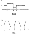
- Fig. 2 shows diagrammatically the amplitude of a customary selection pulse as a function of time t. Selection takes place between t 1 and t 2 and the rephasing of the spins between t 2 and t 3 .
- B tot steady field plus gradient field
- L L 1 s 2
- L is a constant which is dependent on G s and B 0 .
- the additional coils can be controlled, for example in such a manner that between t 2 and t 3 the amplitude of the magnetic field is given by:
- B 0 ⁇ G s s ⁇ L 1 s 2 + L 2 a 2
- a quadratic term occurs not only in the selection direction but also in one of the other directions. Because the selection has been terminated at that instant, this term does not contribute to the warping of the slices.
- a phase variation is introduced in the a direction or the e direction. Correction for this phase variation can be made in the signal processing phase. It is to be noted, however, that such a phase variation also occurs if no additional coils are used during the selection.
- the additional coils enable the second-order terms to be selected so that their adverse effects are minimized for a given experiment. For example, it can be ensured that the concomitant field upon acquisition and evolution is always dependent exclusively on the selection coordinate. To this end, the total field upon acquisition must be given by:
- B 0 + G a a + L 3 s 2 As a result, no distortions will occur in the acquisition and evolution directions, because the "same" offset is imparted to all spins, depending on the slice position s. This can be used only if the loss of signal during rephasing within the slice thickness is small.
- Such a method can also be used for EPI-like experiments.
- quadratic contributions are accumulated, so that in the case of a low field image artefacts may become particularly large and be visible even in the case of a field of 0.5 T.
- Fig. 3 shows diagrammatically the amplitude as a function of time t of the linear gradient during the acquisition in such an experiment.
- the sign of the linear gradient is reversed.
- the additional coils can ensure that at these instants the sign of the quadratic contribution is also reversed so as to compensate the preceding error.
- the additional coils are controlled so that:
- B 0 + G a a + L 3 s 2 for t 4 ⁇ t ⁇ t 5
- B 0 ⁇ G a a ⁇ L 3 s 2 + L 4 a 2 for t 5 ⁇ t ⁇ t 6
- B 0 + G a a ⁇ L 4 a 2 + L 5 s 2 for t 6 ⁇ t ⁇ t 7
- B 0 ⁇ G a a ⁇ L 5 s 2 + L 6 a 2 for t 7 ⁇ t ⁇ t 8 , etc .
- K 1 may be equal to G z 2 /(4B o ) during the selection (with z as the selection direction), whereas K 2 to K 5 are equal to zero.
- then equals B 0 + G z z +G z 2 z 2 /(4B 0 ) + ....
- K 1 as well as K 2 can be equal to -G z 2 /(4B 0 ), whereas K 3 , K 4 and K 5 are equal to zero.
- the additional coils can be designed subject to the same rules as known for the design of coil systems for generating uniform magnetic fields. Examples thereof are described in Magnetic Resonance in Medicine 1, 44-65 (1984) and in J.A.M. Dam and K. Pieterman, Surface cooled, vacuum impregnated superconducting magnet systems (thesis TU Delft, 1989), 120-121.
- Figs. 4, 5 and 6 show diagrammatically some examples of coil systems which are suitable for use as an additional coil system.
- Fig. 4 shows an example of an additional coil system for generating an additional magnetic field which satisfies the relation (9).
- Fig. 5 shows an example of an additional coil system for generating an additional magnetic field which satisfies the relation (10).
- Fig. 6 shows an example of an additional coil system for generating an additional magnetic field which satisfies the relation (12).
- Figs. 7 and 8 show examples of the results that can be obtained by means of the apparatus according to the invention.
- Fig. 7 shows the shape of slices extending perpendicularly to the X-axis
- the reference 59 representing the shape obtained by means of gradient systems customarily used thus far
- the reference 61 represents the shape obtained after addition of suitable additional gradient coil systems.
- Fig. 8 shows a similar diagram for slices extending at an angle of approximately 45° relative to the X- axis and the Z-axis.
- the shape of the slices obtained by means of conventional gradient coil systems is denoted by the reference 63 and that obtained by means of the apparatus according to the invention is denoted by the reference 65.
Landscapes
- Physics & Mathematics (AREA)
- Condensed Matter Physics & Semiconductors (AREA)
- General Physics & Mathematics (AREA)
- Nonlinear Science (AREA)
- Health & Medical Sciences (AREA)
- General Health & Medical Sciences (AREA)
- Nuclear Medicine, Radiotherapy & Molecular Imaging (AREA)
- Radiology & Medical Imaging (AREA)
- Engineering & Computer Science (AREA)
- Signal Processing (AREA)
- High Energy & Nuclear Physics (AREA)
- Magnetic Resonance Imaging Apparatus (AREA)
Abstract
Claims (2)
- Appareil de résonance magnétique, comprenant un système d'aimant (1) destiné à générer un champ magnétique statique d'amplitude B0 dans un espace de mesure (35) orienté parallèlement à un axe z d'un système de coordonnées orthogonales dans lequel les coordonnées sont désignées par les lettres x, y et z, des systèmes de bobines de gradient (3) et des moyens de commande (7, 9) pour alimenter les systèmes de bobines de gradient (3) en courants d'excitation présentant une variation prédéterminée en fonction du temps, les systèmes de bobines de gradient (3) comprenant un système de bobines de gradient linéaire et un système de bobines de gradient supplémentaire, ledit système de bobines de gradient linéaire comprenant des bobines de gradient générant chacune un champ de gradient orienté principalement parallèlement à l'axe z et présentant une variation spatiale comprenant un terme du premier ordre dépendant de l'une des coordonnées du système de coordonnées orthogonales, et ledit système de bobines supplémentaire comprenant des bobines de gradient générant chacune un champ magnétique supplémentaire orienté principalement parallèlement à l'axe z et présentant une variation spatiale comprenant au moins un terme du second ordre dépendant d'une manière prédéterminée d'une ou de plusieurs des coordonnées du système de coordonnées, afin de réduire sensiblement les effets des gradients de champs concomitants, les moyens de commande étant agencés pour alimenter le système de bobines de gradient linéaire et le système de bobines supplémentaire en courants d'excitation, caractérisé en ce que la composante z, Bz, de chacun des champs magnétiques supplémentaires générés par les bobines à partir du système de bobines supplémentaire satisfait à l'une des relations suivantes:


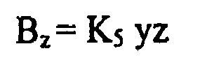
où K1 à K5 sont des constantes,
lesdits moyens de commande étant agencés pour commander ledit système de bobines de gradient linéaire de manière à procurer une impulsion de champ magnétique de gradient dotée d'un gradient linéaire dans une première direction, ladite impulsion donnant lieu à un champ magnétique concomitant, et
pour commander ledit système de bobines de gradient supplémentaire afin de créer, en même temps que ladite impulsion de champ magnétique de gradient linéaire, une impulsion de champ magnétique de gradient contrecarrant la distorsion de champ causée par ledit champ magnétique concomitant, donnant un champ magnétique total dont l'intensité varie uniquement dans ladite première direction et peut être décrite par la somme d'un terme d'ordre zéro, d'un terme linéaire et d'un terme quadratique,
lesdits moyen de commande étant en outre agencés pour procurer une impulsion de champ magnétique de gradient subséquente par le biais de l'activation simultanée desdits systèmes de bobines de gradient linéaire et supplémentaire de telle sorte que, dans le champ magnétique total existant pendant l'impulsion, les signes desdits termes linéaire et quadratique sont inversés comparés à l'impulsion de champ magnétique de gradient précédente, et l'intensité de champ magnétique totale devient en outre dépendante d'un autre terme quadratique qui ne dépend que d'une coordonnée dans une direction perpendiculaire à ladite première direction, l'appareil étant agencé pour compenser les variations de phase de la magnétisation en précession dues audit autre terme quadratique dans une étape de traitement de signaux. - Appareil de résonance magnétique, comprenant un système d'aimant (1) destiné à générer un champ magnétique statique d'amplitude B0 dans un espace de mesure (35) orienté parallèlement à un axe z d'un système de coordonnées orthogonales dans lequel les coordonnées sont désignées par les lettres x, y et z, des systèmes de bobines de gradient (3) et des moyens de commande (7, 9) pour alimenter les systèmes de bobines de gradient (3) en courants d'excitation présentant une variation prédéterminée en fonction du temps, les systèmes de bobines de gradient (3) comprenant un système de bobines de gradient linéaire et un système de bobines de gradient supplémentaire, ledit système de bobines de gradient linéaire comprenant des bobines de gradient générant chacune un champ de gradient orienté principalement parallèlement à l'axe z et présentant une variation spatiale comprenant un terme du premier ordre dépendant de l'une des coordonnées du système de coordonnées orthogonales, et ledit système de bobines supplémentaire comprenant des bobines de gradient générant chacune un champ magnétique supplémentaire orienté principalement parallèlement à l'axe z et présentant une variation spatiale comprenant au moins un terme du second ordre dépendant d'une manière prédéterminée d'une ou de plusieurs des coordonnées du système de coordonnées, afin de réduire sensiblement les effets des gradients de champs concomitants, les moyens de commande étant agencés pour alimenter le système de bobines de gradient linéaire et le système de bobines supplémentaire en courants d'excitation, caractérisé en ce que la composante z, Bz, de chacun des champs magnétiques supplémentaires générés par les bobines à partir du système de bobines supplémentaire satisfait à l'une des relations suivantes:


où K1 à K5 sont des constantes,
lesdits moyens de commande étant agencésa) pour commander ledit système de bobines de gradient linéaire de manière à procurer une impulsion de champ magnétique de gradient dotée d'un gradient linéaire dans une première direction, ladite impulsion donnant lieu à un champ magnétique concomitant, etb) pour commander ledit système de bobines de gradient supplémentaire afin de créer, en même temps que ladite impulsion de champ magnétique de gradient linéaire, une impulsion de champ magnétique de gradient contrecarrant la distorsion de champ causée par ledit champ magnétique concomitant, donnant un champ magnétique total, dont l'intensité peut être décrite par la somme d'un terme d'ordre zéro, d'un terme linéaire qui dépend d'une coordonnée dans ladite première direction et d'un terme quadratique qui ne dépend que d'une coordonnée dans une seconde direction orthogonale à ladite première direction, etc) pour procurer une seconde impulsion subséquente de champ magnétique à gradient par le biais d'une activation simultanée desdits systèmes de bobines de gradient linéaire et supplémentaire de telle sorte que, dans le champ magnétique total existant pendant l'impulsion, les signes desdits termes linéaire et quadratique soient inversés comparés à l'impulsion de champ magnétique de gradient précédente, et l'intensité du champ magnétique total devient en outre dépendante d'un autre terme quadratique qui ne dépend que d'une coordonnée dans ladite première direction, et(d) pour répéter l'étape (c) de telle sorte que, dans le champ magnétique total existant pendant chaque impulsion subséquente, les signes du terme linéaire et des deux termes quadratiques soient inversés comparés à l'impulsion de champ magnétique de gradient précédente, de sorte qu'une accumulation d'une variation de phase induite dans la magnétisation en précession par lesdits termes quadratiques peut être contrecarrée.
Priority Applications (1)
| Application Number | Priority Date | Filing Date | Title |
|---|---|---|---|
| EP97923291A EP0850422B1 (fr) | 1996-07-12 | 1997-06-11 | Appareil de rm comprenant des moyens pour la reduction des effets des gradients concomitants |
Applications Claiming Priority (4)
| Application Number | Priority Date | Filing Date | Title |
|---|---|---|---|
| EP96201973 | 1996-07-12 | ||
| EP96201973 | 1996-07-12 | ||
| PCT/IB1997/000676 WO1998002757A2 (fr) | 1996-07-12 | 1997-06-11 | Appareil a resonance magnetique |
| EP97923291A EP0850422B1 (fr) | 1996-07-12 | 1997-06-11 | Appareil de rm comprenant des moyens pour la reduction des effets des gradients concomitants |
Publications (2)
| Publication Number | Publication Date |
|---|---|
| EP0850422A2 EP0850422A2 (fr) | 1998-07-01 |
| EP0850422B1 true EP0850422B1 (fr) | 2006-04-05 |
Family
ID=8224181
Family Applications (1)
| Application Number | Title | Priority Date | Filing Date |
|---|---|---|---|
| EP97923291A Expired - Lifetime EP0850422B1 (fr) | 1996-07-12 | 1997-06-11 | Appareil de rm comprenant des moyens pour la reduction des effets des gradients concomitants |
Country Status (5)
| Country | Link |
|---|---|
| US (1) | US6107800A (fr) |
| EP (1) | EP0850422B1 (fr) |
| JP (1) | JP3884083B2 (fr) |
| DE (1) | DE69735617T2 (fr) |
| WO (1) | WO1998002757A2 (fr) |
Cited By (1)
| Publication number | Priority date | Publication date | Assignee | Title |
|---|---|---|---|---|
| DE102008028773B4 (de) * | 2008-06-17 | 2012-08-09 | Siemens Aktiengesellschaft | Betriebsverfahren für eine Magnetresonanzanlage mit Kompensation von Maxwell-Termen zweiter Ordnung |
Families Citing this family (6)
| Publication number | Priority date | Publication date | Assignee | Title |
|---|---|---|---|---|
| DE19826864A1 (de) | 1998-06-17 | 1999-12-23 | Philips Patentverwaltung | MR-Verfahren |
| DE10010421C2 (de) * | 2000-03-03 | 2002-01-17 | Siemens Ag | Verfahren zum Betrieb eines Magnetresonanztomographiegeräts und Magnetresonanztomographiegerät |
| JP2003255032A (ja) * | 2002-02-28 | 2003-09-10 | Hitachi Ltd | 核磁気共鳴装置用プローブ |
| DE102008018265B4 (de) | 2008-04-10 | 2011-12-08 | MRB Forschungszentrum für Magnet - Resonanz - Bayern e.V. | Gradientensystem, Kernspinresonanzapparatur, Verfahren zum Erzeu-gen eines bestimmten Gradientenfelds und Computer-Programm |
| DE102017213026A1 (de) * | 2017-07-28 | 2019-01-31 | Siemens Healthcare Gmbh | Gradientenspule zur Erzeugung eines Magnetfeldgradienten und eines Magnetfeldes höherer Ordnung |
| US11243287B2 (en) * | 2019-10-02 | 2022-02-08 | Synaptive Medical Inc. | Real-time compensation of high-order concomitant magnetic fields |
Family Cites Families (5)
| Publication number | Priority date | Publication date | Assignee | Title |
|---|---|---|---|---|
| JPS60189905A (ja) * | 1984-03-09 | 1985-09-27 | Mitsubishi Electric Corp | 高均一磁界発生装置 |
| DE3411222A1 (de) * | 1984-03-27 | 1985-10-10 | Philips Patentverwaltung Gmbh, 2000 Hamburg | Kernspintomograph |
| US5345178A (en) * | 1992-04-21 | 1994-09-06 | Siemens Aktiengesellschaft | Method for setting the current through shim coils and gradient coils in a nuclear magnetic resonance apparatus |
| DE4333440C1 (de) * | 1993-09-30 | 1995-04-06 | Siemens Ag | Verfahren zur Shimmung eines Magnetfeldes in einem Untersuchungsraum eines Kernspinresonanzgerätes |
| EP0721593B1 (fr) * | 1994-07-29 | 2002-04-17 | Koninklijke Philips Electronics N.V. | Appareil a resonance magnetique comprenant un systeme a gradient ameliore |
-
1997
- 1997-06-11 DE DE69735617T patent/DE69735617T2/de not_active Expired - Lifetime
- 1997-06-11 WO PCT/IB1997/000676 patent/WO1998002757A2/fr not_active Ceased
- 1997-06-11 JP JP50577998A patent/JP3884083B2/ja not_active Expired - Fee Related
- 1997-06-11 EP EP97923291A patent/EP0850422B1/fr not_active Expired - Lifetime
- 1997-06-23 US US08/880,374 patent/US6107800A/en not_active Expired - Fee Related
Non-Patent Citations (1)
| Title |
|---|
| COXON R.; MANSFIELD P.: "EPI spatial distortion in non-transverse plane", SOCIETY OF MAGNETIC RESONANCE IN MEDICINE, EIGHTH ANNUAL MEETING AND EXHIBITION, BOOK OF ABSTRACTS, vol. 1, 12 August 1989 (1989-08-12), AMSTERDAM, pages 361 * |
Cited By (1)
| Publication number | Priority date | Publication date | Assignee | Title |
|---|---|---|---|---|
| DE102008028773B4 (de) * | 2008-06-17 | 2012-08-09 | Siemens Aktiengesellschaft | Betriebsverfahren für eine Magnetresonanzanlage mit Kompensation von Maxwell-Termen zweiter Ordnung |
Also Published As
| Publication number | Publication date |
|---|---|
| DE69735617T2 (de) | 2007-01-25 |
| US6107800A (en) | 2000-08-22 |
| DE69735617D1 (de) | 2006-05-18 |
| JP3884083B2 (ja) | 2007-02-21 |
| EP0850422A2 (fr) | 1998-07-01 |
| JPH11512959A (ja) | 1999-11-09 |
| WO1998002757A2 (fr) | 1998-01-22 |
| WO1998002757A3 (fr) | 1998-03-26 |
Similar Documents
| Publication | Publication Date | Title |
|---|---|---|
| US6515478B1 (en) | Method for the correction of artifacts in magnetic resonance images | |
| US5391990A (en) | Iterative shimming method for a basic field magnet of a nuclear magnetic resonance tomography apparatus | |
| JP3445300B2 (ja) | 高速スピンエコーnmrパルス系列での勾配モーメントナリング法 | |
| CN104011557B (zh) | 用于校正mr成像中的主磁场b0的磁场不均匀性的mr设备 | |
| EP3640661B1 (fr) | Procédé et système irm pour la compensation active des champs magnétiques induits par courants de foucault dans l'imagerie par résonance magnétique | |
| EP1004893B1 (fr) | Une méthode de compensation de la magnétisation rémanente de matériaux ferromagnétiques d'un sytème d'IRM | |
| JP3682627B2 (ja) | 磁気共鳴撮像装置 | |
| US5823959A (en) | MR method for determining the magnetic field inhomogeneity in an examination zone, and MR apparatus for carrying out the method | |
| US20080164878A1 (en) | Minimum Energy Shim Coils For Magnetic Resonance | |
| JPH08206094A (ja) | 核スピン断層撮影装置 | |
| US4633179A (en) | Magnetic resonance imaging apparatus using shim coil correction | |
| EP0850422B1 (fr) | Appareil de rm comprenant des moyens pour la reduction des effets des gradients concomitants | |
| US6586935B1 (en) | Magnetic resonance image artifact correction using navigator echo information | |
| EP3828580B1 (fr) | Procédé et système de compensation de champs magnétiques parasites dans un système d'imagerie par résonance magnétique avec plusieurs zones d'examen | |
| US6545476B1 (en) | Method for shimming a magnet system of a MR tomography apparatus and MR tomography apparatus for the implementation of the method | |
| US6229309B1 (en) | MR method | |
| US12553973B2 (en) | Magnetic resonance system, magnetic resonance image correction method, and magnetic resonance imaging method | |
| US6850066B2 (en) | Systems and methods for gradient compensation in magnetic resonance imaging | |
| JP4319035B2 (ja) | 磁気共鳴イメージング装置 | |
| US6294916B1 (en) | NMR and ESR probes for closed loop control of gradient fields | |
| US5929638A (en) | MR method and device for carrying out the method | |
| US6297633B1 (en) | Magnetic resonance tonography system with non-uniform basic field magnet | |
| JPH01284239A (ja) | 磁気共鳴イメージング装置 | |
| EP0124096A2 (fr) | Appareil pour mesurer un signal de résonance magnétique nucléaire | |
| JP2734061B2 (ja) | Mr撮像装置 |
Legal Events
| Date | Code | Title | Description |
|---|---|---|---|
| PUAI | Public reference made under article 153(3) epc to a published international application that has entered the european phase |
Free format text: ORIGINAL CODE: 0009012 |
|
| AK | Designated contracting states |
Kind code of ref document: A2 Designated state(s): DE FR GB NL |
|
| RAP3 | Party data changed (applicant data changed or rights of an application transferred) |
Owner name: KONINKLIJKE PHILIPS ELECTRONICS N.V. |
|
| 17P | Request for examination filed |
Effective date: 19980928 |
|
| 17Q | First examination report despatched |
Effective date: 20031127 |
|
| GRAP | Despatch of communication of intention to grant a patent |
Free format text: ORIGINAL CODE: EPIDOSNIGR1 |
|
| RTI1 | Title (correction) |
Free format text: MR DEVICE WITH MEANS FOR REDUCING THE EFFECTS OF CONCOMITANT FIELD GRADIENTS |
|
| GRAS | Grant fee paid |
Free format text: ORIGINAL CODE: EPIDOSNIGR3 |
|
| GRAA | (expected) grant |
Free format text: ORIGINAL CODE: 0009210 |
|
| AK | Designated contracting states |
Kind code of ref document: B1 Designated state(s): DE FR GB NL |
|
| PG25 | Lapsed in a contracting state [announced via postgrant information from national office to epo] |
Ref country code: NL Free format text: LAPSE BECAUSE OF FAILURE TO SUBMIT A TRANSLATION OF THE DESCRIPTION OR TO PAY THE FEE WITHIN THE PRESCRIBED TIME-LIMIT Effective date: 20060405 |
|
| REG | Reference to a national code |
Ref country code: GB Ref legal event code: FG4D |
|
| REF | Corresponds to: |
Ref document number: 69735617 Country of ref document: DE Date of ref document: 20060518 Kind code of ref document: P |
|
| PG25 | Lapsed in a contracting state [announced via postgrant information from national office to epo] |
Ref country code: GB Free format text: LAPSE BECAUSE OF NON-PAYMENT OF DUE FEES Effective date: 20060705 |
|
| NLV1 | Nl: lapsed or annulled due to failure to fulfill the requirements of art. 29p and 29m of the patents act | ||
| ET | Fr: translation filed | ||
| PLBE | No opposition filed within time limit |
Free format text: ORIGINAL CODE: 0009261 |
|
| STAA | Information on the status of an ep patent application or granted ep patent |
Free format text: STATUS: NO OPPOSITION FILED WITHIN TIME LIMIT |
|
| GBPC | Gb: european patent ceased through non-payment of renewal fee |
Effective date: 20060705 |
|
| 26N | No opposition filed |
Effective date: 20070108 |
|
| PGFP | Annual fee paid to national office [announced via postgrant information from national office to epo] |
Ref country code: FR Payment date: 20090626 Year of fee payment: 13 |
|
| REG | Reference to a national code |
Ref country code: FR Ref legal event code: ST Effective date: 20110228 |
|
| PG25 | Lapsed in a contracting state [announced via postgrant information from national office to epo] |
Ref country code: FR Free format text: LAPSE BECAUSE OF NON-PAYMENT OF DUE FEES Effective date: 20100630 |
|
| PGFP | Annual fee paid to national office [announced via postgrant information from national office to epo] |
Ref country code: DE Payment date: 20120830 Year of fee payment: 16 |
|
| REG | Reference to a national code |
Ref country code: DE Ref legal event code: R119 Ref document number: 69735617 Country of ref document: DE Effective date: 20140101 |
|
| PG25 | Lapsed in a contracting state [announced via postgrant information from national office to epo] |
Ref country code: DE Free format text: LAPSE BECAUSE OF NON-PAYMENT OF DUE FEES Effective date: 20140101 |