EP0850632B1 - Lieu de traitement médical ou dentaire avec fauteuil de traitement - Google Patents
Lieu de traitement médical ou dentaire avec fauteuil de traitement Download PDFInfo
- Publication number
- EP0850632B1 EP0850632B1 EP19970122796 EP97122796A EP0850632B1 EP 0850632 B1 EP0850632 B1 EP 0850632B1 EP 19970122796 EP19970122796 EP 19970122796 EP 97122796 A EP97122796 A EP 97122796A EP 0850632 B1 EP0850632 B1 EP 0850632B1
- Authority
- EP
- European Patent Office
- Prior art keywords
- medical
- suction
- switch
- dental
- station according
- Prior art date
- Legal status (The legal status is an assumption and is not a legal conclusion. Google has not performed a legal analysis and makes no representation as to the accuracy of the status listed.)
- Expired - Lifetime
Links
- 229910000497 Amalgam Inorganic materials 0.000 claims description 6
- 230000008021 deposition Effects 0.000 claims 1
- 238000010586 diagram Methods 0.000 description 3
- 210000003127 knee Anatomy 0.000 description 3
- 210000002414 leg Anatomy 0.000 description 3
- 230000008901 benefit Effects 0.000 description 2
- 238000010276 construction Methods 0.000 description 2
- 230000000694 effects Effects 0.000 description 2
- 238000000605 extraction Methods 0.000 description 2
- 210000003296 saliva Anatomy 0.000 description 2
- 238000011144 upstream manufacturing Methods 0.000 description 2
- 239000002351 wastewater Substances 0.000 description 2
- 230000004913 activation Effects 0.000 description 1
- 230000004888 barrier function Effects 0.000 description 1
- 210000001124 body fluid Anatomy 0.000 description 1
- 239000010839 body fluid Substances 0.000 description 1
- 238000000151 deposition Methods 0.000 description 1
- 230000005611 electricity Effects 0.000 description 1
- 230000002349 favourable effect Effects 0.000 description 1
- 239000012530 fluid Substances 0.000 description 1
- 230000003993 interaction Effects 0.000 description 1
- 239000008141 laxative Substances 0.000 description 1
- 230000002475 laxative effect Effects 0.000 description 1
- 239000007788 liquid Substances 0.000 description 1
- 239000010865 sewage Substances 0.000 description 1
- 230000008719 thickening Effects 0.000 description 1
- XLYOFNOQVPJJNP-UHFFFAOYSA-N water Substances O XLYOFNOQVPJJNP-UHFFFAOYSA-N 0.000 description 1
Images


Classifications
-
- A—HUMAN NECESSITIES
- A61—MEDICAL OR VETERINARY SCIENCE; HYGIENE
- A61C—DENTISTRY; APPARATUS OR METHODS FOR ORAL OR DENTAL HYGIENE
- A61C1/00—Dental machines for boring or cutting ; General features of dental machines or apparatus, e.g. hand-piece design
- A61C1/0007—Control devices or systems
- A61C1/0015—Electrical systems
- A61C1/0023—Foot control
-
- A—HUMAN NECESSITIES
- A61—MEDICAL OR VETERINARY SCIENCE; HYGIENE
- A61G—TRANSPORT, PERSONAL CONVEYANCES, OR ACCOMMODATION SPECIALLY ADAPTED FOR PATIENTS OR DISABLED PERSONS; OPERATING TABLES OR CHAIRS; CHAIRS FOR DENTISTRY; FUNERAL DEVICES
- A61G15/00—Operating chairs; Dental chairs; Accessories specially adapted therefor, e.g. work stands
- A61G15/14—Dental work stands; Accessories therefor
- A61G15/16—Storage, holding or carrying means for dental handpieces or the like
Definitions
- the invention relates to a medical or dental treatment place according to the preamble of claim 1 such treatment place is generally known in practice and z. Tie DE 1 805 515 A and DE 28 23 858 A1 described.
- Most of the types of treatment to be performed at a treatment center are body fluids and / or during treatment from the treatment site Aspirate treatment fluids, which by using a so-called Suction handpiece is used at a dental treatment center So - called saliva ejector, with which saliva and from the patient 's mouth if necessary, treatment liquid can be aspirated.
- the invention has for its object in a medical or dental Treatment place of the type specified at the beginning to improve the usability.
- the treatment place according to the invention is a from the stand or workplace Doctor and / or the helper ergonomically accessible secondary switch for Turn off and preferably also switch on the suction of the suction device again Treatment chair and / or provided in the leg or foot area, the optional can be actuated.
- the effectiveness of the suction device can be handled more easily switched off or off and, if necessary, also switched on.
- Another advantage of the configuration according to the invention is that the Effectiveness of the suction device regardless of the position or movement of the Suction handpiece can be switched on and off. It is e.g. possible the effectiveness of the suction handpiece optionally switch on and off when it is on the Treatment center is in use, e.g. in the patient's mouth.
- This secondary switch is preferably arranged so that either the doctor and the assistant can reach him in the working position. This is the function of the invention both feasible if there is a helper and if the Dentist works without a helper.
- a preferred arrangement area for the switch is the leg area of the Treatment chair or the doctor and / or the assistant. Such an arrangement allows the switch to be operated with one knee or foot, one Hand is not needed and this can perform other activities at the same time.
- the subclaims contain features that are ergonomically favorable Operation of the dental chair allow to be simple and inexpensive manufacturable construction methods and improve the function of the treatment chair.
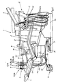
- the main parts of the treatment station 1 are a treatment chair 2 with a adjustable backrest 3 and a headrest 4, a first receiving device 5, which are preferably horizontally movable on a support arm 6 of the treatment chair 2 is held and has a plurality of holding devices 7 for treatment instruments 8, and a second receiving device 9, which is attached to a support arm 11 of the treatment chair 2 is preferably also held horizontally movable and a plurality of holding devices 14 for several treatment instruments.
- the receiving device 5 arranged on the right of the treatment chair in FIG. 1 has several holding devices 7 for associated treatment instruments 8. Also the Receiving device 9 arranged on the left of the treatment chair 2 has several Holding devices 14 for associated treatment instruments 15.
- the Treatment instruments 8, 15 or handpieces Ha, Hb are - as far as necessary - each through a flexible supply line 16, 17 with a supply device connected, the treatment instrument 8, 15 depending on its type with drive energy and / or associated media, such as electricity, light, water, air and the like supplied.
- suction handpieces whose supply line 17a, 17b each through a suction line is formed which extends to a common suction device 18 which e.g. can be arranged in a stand 21 carrying a so-called cuspidor 19, as indicated in Fig. 1, or separately or at
- the presence of several treatment chairs can be arranged centrally
- the first receiving device 5 is assigned to the treating doctor, while the second receiving device 9 is assigned to a helper whose workplace is related the doctor's workplace on the other side of the treatment chair 2 or on the other side thereof Headboard is arranged.
- the treatment instruments intended for the doctor 8 can also be formed by a suction handpiece at least one.
- the holding devices 7, 14 are each through an approximately vertical receiving slot 22 formed in the associated receiving device 5, 9, which is open at the side, so that a rear tapered section of the associated treatment instrument 8, 15 or Handpiece or the supply line 16, 17 can be inserted laterally, the Handpiece with a head-shaped thickening on the upper edge of the Receiving slot 22 rests.
- the holding devices 7, 14 can each be e.g. primary formed by a light barrier Switch 23 may be assigned to the associated when placing and removing Handpiece gives a signal that to switch on and off when removing and depositing of the respective handpiece can serve.
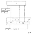
- the Holding devices of the suction handpieces 15a, 15b each have such a switch 23, that by a signal line with the existing one, shown only in FIG. 3 Control device S is connected and the effectiveness of the suction device 18 at Removal switches on and switches off when put down.
- the treatment chair 2 is adjustable in height and by a not shown Height adjustable drive.
- There is a foot switch 24 which is flexible electrical line 25 with the treatment chair and the electrical control device connected is. Due to the flexibility of the line 25, the foot switch 24 can The doctor's workplace and / or the assistant's workplace can be assigned.
- the treatment chair 2 is assigned a safety device with an under the treatment chair 2 close to or on the floor step plate 26, the is pliable or resilient downwards and one when loaded from above arranged below, indicated switch 27 operated by a Signal line is also connected to the control device and during a movement the tread plate 26 down the drive for the vertical adjustment of the Dental chair 2 switches off. This creates a risk of crushing under the Treatment chair avoided.
- the tread plate 26 is located under the seat of the Treatment chair 2, above which a free space of the projecting treatment chair 2 is available.
- a foot switch or a footplate 26 a switch 27 with or without a safety device described above as a secondary switch 27 to Einund Switch off the suction of the suction device 18 to use.
- the tread plate 26 and a double occupancy of the Switch 27 is used to selectively turn the suction of the suction device 18 on and off off. This requires a signal that indicates the respective priority of the Double occupancy controls.
- the associated switch 23 can be used in each case, which is switched when the associated handpiece 15a, 15b is removed.
- a laxative from the bowl 19 Suction line section 20a a collection container 31 for the waste water with an in Downstream valve, a so-called shell valve 32, provided to open and close the electrically or electrically / pneumatically by a directional valve 33 is close and preferably by the force of a spring 34 in its closed position is acted upon.
- the flexible suction lines 17a, 17b of the suction handpieces are in Parallel connection in each case by a suction line section 20b with a common one Suction line 20 connected to which the suction line section 20a is also connected.
- the suction line sections 20b each have a valve, a so-called selection valve V1, arranged, preferably upstream of which a filter F is arranged.
- a so-called Suction flow valve V2 In of the suction line 20 extending to the suction device 18 is a valve, a so-called Suction flow valve V2, arranged to open and close the suction line 20.
- valves V1, V2 are already electrical or electrical / pneumatic to open and close by an associated directional control valve 35, 36 and preferably acted upon by the force of a spring 34 in the closed position.
- an amalgam separator 37 is integrated, which separates the amalgam, the suction exhaust air and Waste water leave the suction device 18 separately. This is a so-called Wet system suction.
- the collecting container 31 is a level meter 38 for minimum and maximum levels assigned, on whose signals the control device S the valve 32 for the purpose Emptying controls.
- FIG. 3 differs from the above Embodiment in that the amalgam separator 37 as a separating amalgam separator combination 37a upstream of valve V2 in the flow direction , wherein the bowl 19 is connected to the amalgam separator combination 37a and from the combination 37a a discharge line 39 via a siphon 41 to Sewage network extends.
- This is a dry system extraction.
- suction device 18 and the Separator combination 37a the treatment chair 2 z. B. in the frame 21 or in the presence of several dental chair units with a central suction device 18 to provide a separator combination 37a.
- the effectiveness of the suction device 18 can in each case by opening and closing the relevant suction handpiece associated valve V1 or V2 or by an input or Switching off the suction device 18 can be switched on or off.
- The is accordingly Control device S set up. It can be designed so that when actuated the switch 27, the effectiveness of the suction device 18 remains switched off until the switch 27 is released. It is also possible, the double assignment of the switch 27 is so control that when the switch 27 or the tread plate 26 is actuated, the suction device 18th is turned off.
- switch 28 instead of or in addition to the switch 27 Leg area of the workplace for the doctor and / or the workplace for the assistant to arrange the one or the effectiveness of the suction device 18 when actuated switches off or switches off if this has previously been switched on.
- the switch 28 or the electrical control is preferably configured in this way trained that when the switch is actuated again after it is switched off the suction device 18 is switched on again.
- switch 28 e.g. in Knee height on one or the other side or on both sides of the treatment chair 2 to be arranged so that it can be actuated by a knee movement. It is also possible that Switch 28 on the existing foot switch 24 or on an additional foot switch to arrange, the fixed or by a flexible electrical line with the Dental chair can be connected and thus can be adjusted.
- This alternative embodiment is suitable for a treatment place with only one Suction handpiece or several suction handpieces 15a, 15b. If several Suction handpieces 15a, 15b are present, they are always connected to the suction flow at the same time connected because the valves V1 and these controlling switching signals are missing. Since the Suction handpieces 15a, 15b each generate only one intake air flow, it is not considered disruptive to look at if the one or more located in the receiving device 9 Suction handpieces also suck air when not in use.
- each Suction handpiece 15a, 15b in the easily accessible area at the workplace of the doctor and / or the assistant, e.g. at the treatment chair 2 or directly to the Suction handpieces to arrange an additional switch (not shown) at the Actuation the associated valve V1 is opened so that only the associated Suction handpiece is connected to the suction stream while that or the others Suction handpieces remain switched off by the associated valve (s) V1.
Landscapes
- Health & Medical Sciences (AREA)
- Public Health (AREA)
- Life Sciences & Earth Sciences (AREA)
- Animal Behavior & Ethology (AREA)
- General Health & Medical Sciences (AREA)
- Veterinary Medicine (AREA)
- Water Supply & Treatment (AREA)
- Oral & Maxillofacial Surgery (AREA)
- Dentistry (AREA)
- Epidemiology (AREA)
- Engineering & Computer Science (AREA)
- Accommodation For Nursing Or Treatment Tables (AREA)
- Dental Tools And Instruments Or Auxiliary Dental Instruments (AREA)
Claims (11)
- Poste de traitement médical ou dentaire (1) comportant:caractérisé en ce que,un fauteuil de soins (2)un ou plusieurs instruments à main (8,15),lequel ou lesquels, en cas de non utilisation, peut ou peuvent être respectivement déposé(s) dans un dispositif de support (7,14),et dont un ou plusieurs instruments à main (8,15) est ou sont respectivement constitué(s) par un instrument à main aspirant (15a, 15b),qui est raccordé par une conduite d'aspiration flexible (17a,17b) à un appareil d'aspiration (18),
il est prévu un commutateur primaire (23) pour le branchement et le débranchement automatiques du fonctionnement de l'appareil d'aspiration (18) lors de la prise et de la dépose de l'instrument à main aspirant (15a, 15b) et
Il est prévu un commutateur secondaire (27;28) pour le débranchement et le branchement du fonctionnement de l'appareil d'aspiration (18),qui est disposé dans une position accessible au poste de travail du médecin et/ou d'une assistante au niveau du fauteuil de soins (2) et/ou dans la région des jambes ou des pieds du médecin et/ou de l'assistante. - Poste de traitement médical ou dentaire selon la revendication 1,
Caractérisé en ce que,
le commutateur secondaire (27) est un commutateur à pied ou coopère avec une pédale horizontale (26) ou un commutateur à jambe (28). - Poste de traitement médical ou dentaire selon la revendication 2,
Caractérisé en ce que,
la pédale (26) est agencée sur le sol existant ou sur un petit socle du fauteuil de soins (2). - Poste de traitement médical ou dentaire selon la revendication 2 ou 3,
Caractérisé en ce que,
la pédale (26) s'étend sur toute ou quasiment sur toute la largeur du fauteuil de soins (2). - Poste de traitement médical ou dentaire selon l'une des revendications précédentes,
Caractérisé en ce que,
lors d'actionnements consécutifs répétés du commutateur secondaire (27) conçu en qualité d'inverseur va-et-vient, le dispositif d'aspiration (18) est alternativement débranché et branché. - Poste de traitement médical ou dentaire selon l'une des revendications précédentes,
Caractérisé en ce que,
le commutateur secondaire (27) est constitué par un commutateur existant ayant une double position fonctionnelle. - Poste de traitement médical ou dentaire selon la revendication 6,
Caractérisé en ce que,
le commutateur primaire (23) commande la priorité de la double position fonctionnelle du commutateur secondaire (27) de telle sorte qu'après un actionnement du commutateur primaire (23) le branchement ou débranchement de l'appareil d'aspiration (18) a la priorité vis-à-vis de l'autre position. - Poste de traitement médical ou dentaire selon l'une des revendications précédentes,
Caractérisé en ce que,
le commutateur primaire (23) est disposé sur le dispositif de support (7, 14) et lors d'une prise ou dépose de l'instrument à main aspirant concerné (15a, 15b) est actionné par celui-ci. - Poste de traitement médical ou dentaire selon l'une des revendications précédentes,
Caractérisé en ce que,
le commutateur secondaire (27) et/ou la pédale (26) est ou sont agencé(s) sous une protubérance latérale du fauteuil de soins (2) et font partie d'un circuit de commutation de sécurité pour la mise hors service du mouvement de réglage de redressement du fauteuil de soins (2). - Fauteuil de soins médicaux ou dentaires selon l'une des revendications précédentes,
Caractérisé en ce que,
une soupape (V1, V2) est disposée respectivement dans une section de conduite d'aspiration (17a, 17b) raccordée à au moins un instrument à main aspirant (15a,15b) et/ou dans une conduite d'aspiration commune (20), soupape qui peut être ouverte ou fermée sélectivement au moyen d'un moteur. - Poste de traitement médical ou dentaire selon l'une des revendications précédentes,
Caractérisé en ce que,
un séparateur d'amalgame est intégré dans le dispositif d'aspiration ou dans une conduite d'aspiration (20) menant à l'appareil d'aspiration (18), de préférence dans la direction d'écoulement en amont d'une soupape (V2).
Applications Claiming Priority (4)
| Application Number | Priority Date | Filing Date | Title |
|---|---|---|---|
| DE29622496U | 1996-12-27 | ||
| DE29622496 | 1996-12-27 | ||
| DE29717025U DE29717025U1 (de) | 1996-12-27 | 1997-09-23 | Ärztlicher oder zahnärztlicher Behandlungsplatz mit einem Behandlungsstuhl |
| DE29717025U | 1997-09-23 |
Publications (3)
| Publication Number | Publication Date |
|---|---|
| EP0850632A2 EP0850632A2 (fr) | 1998-07-01 |
| EP0850632A3 EP0850632A3 (fr) | 1999-06-02 |
| EP0850632B1 true EP0850632B1 (fr) | 2003-05-28 |
Family
ID=26059792
Family Applications (1)
| Application Number | Title | Priority Date | Filing Date |
|---|---|---|---|
| EP19970122796 Expired - Lifetime EP0850632B1 (fr) | 1996-12-27 | 1997-12-23 | Lieu de traitement médical ou dentaire avec fauteuil de traitement |
Country Status (3)
| Country | Link |
|---|---|
| EP (1) | EP0850632B1 (fr) |
| JP (1) | JPH10272164A (fr) |
| DK (1) | DK0850632T3 (fr) |
Families Citing this family (1)
| Publication number | Priority date | Publication date | Assignee | Title |
|---|---|---|---|---|
| NL1031827C2 (nl) | 2006-05-17 | 2007-11-20 | Univ Eindhoven Tech | Operatierobot. |
Family Cites Families (2)
| Publication number | Priority date | Publication date | Assignee | Title |
|---|---|---|---|---|
| DE1805515A1 (de) * | 1968-10-26 | 1970-05-14 | Siemens Ag | Mit einem Patientenstuhl gekuppelter zahnaerztlicher Geraetestaender |
| DE3302558A1 (de) * | 1983-01-26 | 1984-07-26 | Kaltenbach & Voigt Gmbh & Co, 7950 Biberach | Fusssteuervorrichtung, insbesondere fuer zahnaerztliche geraete |
-
1997
- 1997-12-23 DK DK97122796T patent/DK0850632T3/da active
- 1997-12-23 EP EP19970122796 patent/EP0850632B1/fr not_active Expired - Lifetime
- 1997-12-29 JP JP9368783A patent/JPH10272164A/ja not_active Withdrawn
Also Published As
| Publication number | Publication date |
|---|---|
| JPH10272164A (ja) | 1998-10-13 |
| EP0850632A2 (fr) | 1998-07-01 |
| DK0850632T3 (da) | 2003-07-21 |
| EP0850632A3 (fr) | 1999-06-02 |
Similar Documents
| Publication | Publication Date | Title |
|---|---|---|
| DE3032161C2 (de) | Saug- und Sammelvorrichtung für eine Harnabsaugvorrichtung | |
| EP0538641B1 (fr) | Laser chirurgical avec un système d'évacuation des fumées | |
| DE3232701C2 (de) | Verfahren und Vorrichtung zum Beseitigen von Schadstoffen aus einem zahnärztlichen Behandlungszimmer | |
| EP3517012B1 (fr) | Station de base pour un aspirateur | |
| DE2713320C2 (fr) | ||
| EP0023036A1 (fr) | Installation d'aspiration dentaire | |
| DE112013005467B4 (de) | Mit einer Blende versehene Absaugwanne für dentale Tätigkeiten ausserhalb des Mundraums | |
| DE2214248A1 (de) | Zahnärztliches Gerät | |
| DE3026763A1 (de) | Vakuum-spueltoilettensystem | |
| DE2535164C2 (de) | Schlammabzugsvorrichtung eines Dekantierers zur Wasseraufbereitung nach dem Schlammbettverfahren mit pulsierendem Schlammbett | |
| DE3382803T2 (de) | Spülklosettbecken | |
| EP0850632A2 (fr) | Lieu de traitement médical ou dentaire avec fauteuil de traitement | |
| DE29717025U1 (de) | Ärztlicher oder zahnärztlicher Behandlungsplatz mit einem Behandlungsstuhl | |
| DE202009008764U1 (de) | Mobiler Pflegestuhl | |
| EP2456390A1 (fr) | Dispositif collecteur destiné à recueillir des particules présentes dans le fluide buccal provenant de la bouche d'un patient pendant des traitements dentaires | |
| DE9402455U1 (de) | Absaugvorrichtung, insbesondere für Dentallabor-Arbeitsplätze | |
| DE3514331C2 (fr) | ||
| DE9405232U1 (de) | Vorrichtung zur Absaugung übler Gerüche in WC-Anlagen o.dgl. | |
| EP1752110B1 (fr) | Adaptateur pour un système d'aspiration dentaire | |
| DE8904379U1 (de) | Zahnärztliche Absaugeinrichtung enthaltend mehrere Abwasserquellen | |
| DE1466974B1 (de) | Dentaleinheit | |
| DE212005000060U1 (de) | Einstellbares/r Krankenhaus- oder Pflegebett, Behandlungs- oder Untersuchungstisch | |
| EP0386449A2 (fr) | Toilette pour aéronef | |
| DE3726394A1 (de) | Vorrichtung zur absaugung von aerosol | |
| DE2163501A1 (de) | Saugeinrichtung, insbesondere fuer medizinische zwecke |
Legal Events
| Date | Code | Title | Description |
|---|---|---|---|
| PUAI | Public reference made under article 153(3) epc to a published international application that has entered the european phase |
Free format text: ORIGINAL CODE: 0009012 |
|
| AK | Designated contracting states |
Kind code of ref document: A2 Designated state(s): DE DK IT SE |
|
| AX | Request for extension of the european patent |
Free format text: AL;LT;LV;MK;RO;SI |
|
| PUAL | Search report despatched |
Free format text: ORIGINAL CODE: 0009013 |
|
| AK | Designated contracting states |
Kind code of ref document: A3 Designated state(s): AT BE CH DE DK ES FI FR GB GR IE IT LI LU MC NL PT SE |
|
| AX | Request for extension of the european patent |
Free format text: AL;LT;LV;MK;RO;SI |
|
| 17P | Request for examination filed |
Effective date: 19991109 |
|
| AKX | Designation fees paid |
Free format text: DE DK IT SE |
|
| 17Q | First examination report despatched |
Effective date: 20020206 |
|
| GRAH | Despatch of communication of intention to grant a patent |
Free format text: ORIGINAL CODE: EPIDOS IGRA |
|
| GRAH | Despatch of communication of intention to grant a patent |
Free format text: ORIGINAL CODE: EPIDOS IGRA |
|
| GRAA | (expected) grant |
Free format text: ORIGINAL CODE: 0009210 |
|
| AK | Designated contracting states |
Designated state(s): DE DK IT SE |
|
| RAP1 | Party data changed (applicant data changed or rights of an application transferred) |
Owner name: KALTENBACH & VOIGT GMBH & CO. KG |
|
| REF | Corresponds to: |
Ref document number: 59710170 Country of ref document: DE Date of ref document: 20030703 Kind code of ref document: P |
|
| REG | Reference to a national code |
Ref country code: DK Ref legal event code: T3 |
|
| REG | Reference to a national code |
Ref country code: SE Ref legal event code: TRGR |
|
| PLBE | No opposition filed within time limit |
Free format text: ORIGINAL CODE: 0009261 |
|
| STAA | Information on the status of an ep patent application or granted ep patent |
Free format text: STATUS: NO OPPOSITION FILED WITHIN TIME LIMIT |
|
| 26N | No opposition filed |
Effective date: 20040302 |
|
| PGFP | Annual fee paid to national office [announced via postgrant information from national office to epo] |
Ref country code: SE Payment date: 20041228 Year of fee payment: 8 Ref country code: DK Payment date: 20041228 Year of fee payment: 8 |
|
| PG25 | Lapsed in a contracting state [announced via postgrant information from national office to epo] |
Ref country code: SE Free format text: LAPSE BECAUSE OF NON-PAYMENT OF DUE FEES Effective date: 20051224 |
|
| PG25 | Lapsed in a contracting state [announced via postgrant information from national office to epo] |
Ref country code: DK Free format text: LAPSE BECAUSE OF NON-PAYMENT OF DUE FEES Effective date: 20060102 |
|
| REG | Reference to a national code |
Ref country code: DK Ref legal event code: EBP |
|
| EUG | Se: european patent has lapsed | ||
| PGFP | Annual fee paid to national office [announced via postgrant information from national office to epo] |
Ref country code: IT Payment date: 20151230 Year of fee payment: 19 Ref country code: DE Payment date: 20151229 Year of fee payment: 19 |
|
| REG | Reference to a national code |
Ref country code: DE Ref legal event code: R119 Ref document number: 59710170 Country of ref document: DE |
|
| PG25 | Lapsed in a contracting state [announced via postgrant information from national office to epo] |
Ref country code: IT Free format text: LAPSE BECAUSE OF NON-PAYMENT OF DUE FEES Effective date: 20161223 |
|
| PG25 | Lapsed in a contracting state [announced via postgrant information from national office to epo] |
Ref country code: DE Free format text: LAPSE BECAUSE OF NON-PAYMENT OF DUE FEES Effective date: 20170701 |