EP0850656B1 - Elément de raidissement pour augmenter le flux d'un liquide dans un dispositif médical - Google Patents
Elément de raidissement pour augmenter le flux d'un liquide dans un dispositif médical Download PDFInfo
- Publication number
- EP0850656B1 EP0850656B1 EP97310499A EP97310499A EP0850656B1 EP 0850656 B1 EP0850656 B1 EP 0850656B1 EP 97310499 A EP97310499 A EP 97310499A EP 97310499 A EP97310499 A EP 97310499A EP 0850656 B1 EP0850656 B1 EP 0850656B1
- Authority
- EP
- European Patent Office
- Prior art keywords
- cross
- catheter
- stylet
- stiffening member
- section
- Prior art date
- Legal status (The legal status is an assumption and is not a legal conclusion. Google has not performed a legal analysis and makes no representation as to the accuracy of the status listed.)
- Expired - Lifetime
Links
Images




Classifications
-
- A—HUMAN NECESSITIES
- A61—MEDICAL OR VETERINARY SCIENCE; HYGIENE
- A61M—DEVICES FOR INTRODUCING MEDIA INTO, OR ONTO, THE BODY; DEVICES FOR TRANSDUCING BODY MEDIA OR FOR TAKING MEDIA FROM THE BODY; DEVICES FOR PRODUCING OR ENDING SLEEP OR STUPOR
- A61M25/00—Catheters; Hollow probes
- A61M25/01—Introducing, guiding, advancing, emplacing or holding catheters
- A61M25/0102—Insertion or introduction using an inner stiffening member, e.g. stylet or push-rod
-
- A—HUMAN NECESSITIES
- A61—MEDICAL OR VETERINARY SCIENCE; HYGIENE
- A61M—DEVICES FOR INTRODUCING MEDIA INTO, OR ONTO, THE BODY; DEVICES FOR TRANSDUCING BODY MEDIA OR FOR TAKING MEDIA FROM THE BODY; DEVICES FOR PRODUCING OR ENDING SLEEP OR STUPOR
- A61M25/00—Catheters; Hollow probes
- A61M25/01—Introducing, guiding, advancing, emplacing or holding catheters
- A61M25/06—Body-piercing guide needles or the like
- A61M25/0612—Devices for protecting the needle; Devices to help insertion of the needle, e.g. wings or holders
-
- A—HUMAN NECESSITIES
- A61—MEDICAL OR VETERINARY SCIENCE; HYGIENE
- A61M—DEVICES FOR INTRODUCING MEDIA INTO, OR ONTO, THE BODY; DEVICES FOR TRANSDUCING BODY MEDIA OR FOR TAKING MEDIA FROM THE BODY; DEVICES FOR PRODUCING OR ENDING SLEEP OR STUPOR
- A61M25/00—Catheters; Hollow probes
-
- A—HUMAN NECESSITIES
- A61—MEDICAL OR VETERINARY SCIENCE; HYGIENE
- A61M—DEVICES FOR INTRODUCING MEDIA INTO, OR ONTO, THE BODY; DEVICES FOR TRANSDUCING BODY MEDIA OR FOR TAKING MEDIA FROM THE BODY; DEVICES FOR PRODUCING OR ENDING SLEEP OR STUPOR
- A61M25/00—Catheters; Hollow probes
- A61M25/0043—Catheters; Hollow probes characterised by structural features
Definitions
- the present invention relates generally to the field of medical devices.
- this invention pertains to a stylet that helps increase the rigidity of a medical device, particularly when the medical device is being inserted.
- Peripherally inserted central catheters are used to access the vascular system.
- PICCs are used when long-term-vascular access is required (e.g., more than two weeks indwelling time in a patient) to avoid multiple injections of the patient.
- a PICC is a long catheter that is often inserted mid-way on a patient's arm and the end of the catheter is often placed in the superior vena cava of the heart.
- PICCs often provide access to a patient's vascular system for chemotherapy or other types of intravenous medication.
- the catheter must be soft and pliable for ease of navigation and to avoid trauma to a blood vessel.
- the catheter must also be made of bio-compatible materials so that it will not irritate a patient's veins during the catheter's long dwelling time.
- PICC lines made of a soft bio-compatible material are very difficult to insert into a patient because its soft or pliable construction causes the PICC to often collapse and bend before entering the patient's veins.
- a flexible metal stylet or guidewire
- Guidewires cause several problems. There is increased friction between the guidewire and the inner wall of the catheter since the catheter often makes many turns and twists before reaching its final destination. As a result, it is often difficult to manipulate and then remove the guidewire.
- the use of the guidewire also introduces the possibility that the guidewire may perforate a catheter when it is forced against the catheter.
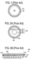
- a cross-section of a prior art guidewire 102 is shown in a small catheter 100 with minimal space for the fluid flow area 104.
- a cross-sectional area of guidewire 102 occupies about 70% of the cross-sectional area of the lumen of catheter 100. Consequently, only about 30% of the cross-sectional area of catheter's 100 lumen is available as the fluid flow area 104.
- FIG 2A Another prior art embodiment of a guidewire 200 is shown in Figure 2A .
- the guidewire 200 is made of three elements: a flat ribbon of material 207 adjacent to a core 209, both of which are disposed within a twisted-helical coil 205.
- the resulting fluid flow area 203 between the guidewire 200 and the catheter 201 is minimal.
- FIG. 2B A side view of the guidewire 200 of Figure 2A is illustrated in Figure 2B .
- the helical coil 205 is welded on both ends of the ribbon 207 at 211a and 211b.
- the twists of the helical coil 205 are often not visible to the naked eye, but for the sake of clarity, the space between each of the coils in coil 205 have been exaggerated in Figure 2B .
- the coil 205 often flexes as it twists and turns with the catheter 201. This allows some fluid to flow in between the coils 205 and around the core 209, which provides stiffness, and the flat ribbon 207.
- the core 209 can also be welded to the flat ribbon 207.
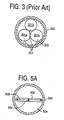
- Figure 3 illustrates a cross-section of another prior art embodiment in which the guidewire 301 is made of three separate wires 301a-c, which are braided together. Each wire may have a diameter of approximately 0.2 mm (0.008 inches) while the internal diameter of the catheter 300 may be 0.81 mm (0.032 inch).
- Figure 3 illustrates one disadvantage of the prior art systems. The length of the guidewire cannot be changed without altering or compromising the structural integrity of the guidewire. For example, guidewire 301 of Figure 3 cannot be cut without compromising or destroying the structural integrity of the guidewire 301 as its three wires 301a-c will unravel and separate. The same is true for the guidewire 200 of Fig. 2 and its three components, 205, 207 and 209.
- a guidewire (or stylet) serves as a stiffening member in a medical device, such as for example, a PICC catheter, during insertion of the medical device. It is also desirable that the shape of the stiffening member helps increase fluid flow around the guidewire (or stylet) disposed within the medical device.
- the present invention describes a vascular access device as defined in claim 1.
- the present invention comprises an elongated, substantially rectangular stylet that is disposed within a catheter, such that the stylet can occupy less than half of the lumen area of the catheter. As a result, adequate fluid flow is allowed between the stylet and the inner wall of the catheter. This increases patient comfort.
- the stylet is made of substantially flat stock such that in cross-section, the longer dimension of the stylet closely approximates or is slightly smaller than the internal diameter of the catheter.
- the flat stock is twisted over the length of the stylet to achieve equal rigidity or bendability over the entire length of the stylet in any axis.
- pitches i.e., number of twists or turns per inch
- the pitch within a single stylet may be varied to create multiple stiffnesses within a single stylet.
- the proximal end can have a greater pitch than the digital end of a stylet to create a softer proximal end. This is beneficial since the proximal end is inserted first into the patient.
- the elongated, substantially rectangular stylet comprises the majority of the cross-sectional area of the substantially rectangular stiffening member.
- substantially rectangular as defined, can also include a cross-sectional area of a single element that is shaped like various versions of an I-beam, a dog-bone, an ellipse, an oval, and a rectangle.
- the cross-section of the substantially rectangular stylet has a long first axis and a short second axis that is not aligned with the first axis. The first and second axes, however, are coupled together and are part of a single element stylet.
- the cross-sectional area of the stiffening member is usually such that one dimension (the "long” dimension) is at least twice or most preferentially, eight times the length of the other dimension (the "short” dimension); in this way, the stiffening member is substantially rectangular at least in cross-sectional view. This allows the flushing fluid to flow through at least half of the lumen area within the catheter, and more preferably through about 80% of the catheter's lumen area.
- a cross-sectional area of the elongated stylet is a percentage up to 65% of a cross-sectional area of the catheter's lumen.
- the available fluid flow area is the area not occupied by the elongated stylet within the catheter's lumen.
- the cross-sectional area of the elongated stylet is formed substantially by a single stiffening member.
- a coating can be placed around the single stiffening member. The coating does not substantially decrease the fluid flow around the stylet.
- the coating can be selected from a group consisting of a hydrogel, or TeflonTM, which applies to a tetrafluorethylene fluorocarbon polymer and a fluorinated ethylene-propylene resin.
- the present invention provides several advantages over the prior art.
- the present invention increases fluid flow within a catheter without sacrificing the mechanical stiffening provided by the stylet. This is especially important in flushable guidewire systems where unhindered flow of a flushing solution is essential.
- the flushing solution helps reduce the friction between the guidewire (or stylet) and the inner wall of the catheter while the catheter is twisting and turning through the blood vessel.
- the flushing solution aids in manipulating and finally removing the stylet. This reduces the possibility that the guidewire may become jammed in the catheter and require removal of the catheter from the patient. It is also helpful to infuse fluid through the catheter while advancing the catheter through the patient.
- the present invention allows maximum stylet effectiveness while still retaining full flushing capabilities.
- the present stylet invention may also be easily cut to adjust the length of the catheter without compromising or destroying the structural integrity of the stylet.
- the structural integrity of the prior art guidewires 200 and 301 of Figures 2 and 3 are lost if the guidewires 200 and 301 are cut, because components (205, 207, 209 and 301a-c, respectively) will unravel and separate.
- the stylet of the present invention does not need to be removed before the catheter is cut.
- the stylet does not need to be presized to fit the exact length of the catheter. Because a physician or a nurse cannot usualiy determine with absolute accuracy the length of catheter needed for a particular patient, the present invention provides additional flexibility and time-efficiency to the busy medical practitioner.
- the present stylet is much easier to manufacture than prior art examples since it is a single element.
- the prior art guidewires illustrated in Figure 3 and in Figure 2A comprise three elements.
- the present invention should decrease manufacturing costs and also decrease overall health-care costs.
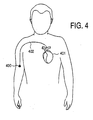
- a PICC 402 is used when long-term-vascular access is required, for example, more than two weeks, in order to avoid traumatizing the patient with multiple injections.
- a PICC is a longer catheter that is often inserted midway on a patient's arm 400 initially and the end of the catheter is often placed in the superior vena cava of the heart 401.
- a PICC must often travel anywhere from six to twenty inches, depending on the size of the patient, before its distal end (the end farthest from the original entry point) reaches its final indwelling point.
- a stylet is often used to help stiffen the catheter, which is often made of a soft bio-compatible material.
- the soft construction of a catheter often causes the PICC to collapse and/or bend before entering a patient's veins.
- a flexible metal stylet enables one to more quickly and efficiently insert a PICC. Since the PICC 402 and thus the stylet, must travel through many natural barriers and a fairly long distance through the patient's body, maximum fluid flow between the stylet and the catheter is necessary for increased patient comfort and decreased incidents of trauma to the patient's veins.
- FIG. 5A a cross-section of one embodiment of the present invention is illustrated.
- a single-elongated, substantially rectangular stiffening member 502 is shown within a catheter 500.
- Substantially rectangular is defined to mean that in cross-section, a first dimension or first axis 508 of the stiffening member 502 is at least twice the length of a second dimension or second axis 506 that is perpendicular to the first dimension.
- first axis 508 is eight-times the length of second axis 506.
- stiffening member in cross-section
- first axis 508 and second axis 506 can be used within the scope of the present invention.
- first (or long) axis 508 could be six times longer than second (or short) axis 506.
- first axis 508 provides most of the bending stiffness of elongated stiffening member 502. Bending stiffness is the force required to bend an object. For example, steel has a greater bending stiffness than rubber.
- a fluid flow area 504 through at least more than half of the internal area or lumen of the catheter 500 is shown. The fluid flow area 504 is much greater than the prior art fluid flow areas (104, 203 and 303) illustrated in Figures 1, 2A and 3, respectively.
- stiffening member 502 can operate as a stylet by providing column strength to the catheter 500 to aid insertion of the catheter, its substantially rectangular shape (as seen in cross-section) does not greatly reduce the fluid flow like prior art guidewires.
- the stylet has a cross-sectional area that is defined substantially by the cross-sectional area of the elongated, substantially rectangular stiffening member 502.
- an additional treatment such as a coating (e.g., a hydrogel or a TeflonTM or TeflonTM type material) can be placed around the stiffening member 502.
- a coating e.g., a hydrogel or a TeflonTM or TeflonTM type material
- TeflonTM applies to tetrafluorethylene fluorocarbon polymers and fluorinated ethylene-propylene resins.
- the coating should not substantially increase the diameter or cross-sectional area of the stiffening member 502. Thus, the coating should not dramatically decrease fluid flow area 504.
- a cross-section of the flat section of stiffening member 502 is shown that is less than the internal diameter of the catheter 500. It is to be appreciated that the flat section of stiffening member 502, as shown in cross-section, may also closely approximate the internal diameter of catheter 500 in another embodiment.
- Stiffening member 502 may be made of metal or plastic. It will be apparent to one skilled in the art that stiffening member 502 may be made of any bio-compatible material that provides column strength to catheter 500 with minimal irritation to the patient's blood vessel. It will also be apparent to one of skill in the art that the present invention may also be used in other catheters, such as, a mid-line catheter and is not restricted to PICCs.
- FIG. 5B A cross-section of another embodiment of a stiffening member is shown in Figure 5B .
- Stiffening member 510 is disposed within the lumen of catheter 500 with a fluid flow area 511.
- the length of the long axis or first axis of stiffening member 510 is about four times greater than the length of its short axis or second axis.
- stiffening member 510 had a first axis of 0.032th of an inch, a second axis of about 0.008th of an inch and the internal diameter of the catheter is 0.035th of an inch
- the cross-sectional area of stiffening member 510 is about 27% of the cross-sectional area of the lumen for catheter 500. This means that there is a fluid flow area 511 of about 73% in an embodiment with those dimensions.
- FIG. 5C The cross-section of an even larger embodiment of a similarly shaped stiffening member is illustrated in Figure 5C .
- the stiffening member 512 is disposed within the lumen of catheter 500.
- the fluid flow area 513 of Fig. 5C is less than the fluid flow area 511 of Fig. 5B because the size of the stiffening member has increased.
- stiffening member 512 occupies about 48% of the lumen area of the catheter 500 in cross-section.
- Figure 5C illustrates an embodiment where the long axis is about twice the length of the short axis. This results in a fluid flow of about 52% of the cross-sectional area of the lumen of the catheter 500.
- the ratio of long axis to short axis in the cross-section of the various stiffening members shown in Figs. 5A-C is meant to be illustrative and not limiting.
- Figures 6A-C illustrate a cross-section of a series of different dog-bone or dumbbell-shaped embodiments for a stiffening member.
- the internal diameter of the catheter 600 is 0.035th of an inch for an exemplary catheter.
- the long axis (defined like 508 of Fig. 5A )of the stiffening member 602, 604, and 608 of each respective figure ( Figs. 6A-C ) is 0.032th of an inch.
- the thin middle portion of stiffening member 602 can have a thickness of about 0.004th of an inch and the two thicker end portions of stiffening member 602 (which are contiguous to the middle portion) can be about 0.008th of an inch in an exemplary embodiment. If one considers the thickness of the end portions to be a "short axis", in this case 0.008th of an inch, then the "long axis" of 0.032th of an inch is four times greater than the short axis.
- the stiffening member 602, in cross-section occupies about 16.8% of the cross-sectional area of the lumen of catheter 600.
- the fluid flow area 603, in this embodiment is about 83.2%, which is a significant increase over the prior art.
- the middle portion of stiffening member 604 is wider than the middle portion of Fig. 6A , such that the cross-sectional area of stiffening member 604 is increased to about 27% of the cross-sectional area of the lumen of catheter 600.
- the short axis (defined by the thickness of the two end portions), however, is slightly smaller than the short axis of Fig. 6A . Consequently, the fluid flow area 605 has decreased accordingly to about 73% of the cross-sectional area of the lumen of catheter 600.
- the middle portion and the two end portions of stiffening member 608 are further increased in size.
- the middle portion can be about 0.012th of an inch and the two end portions ("short axis") can be about 0.012th of an inch, which means the long axis of 0.032th of an inch is about 2.67 times greater than the short axis in this embodiment.
- the stiffening member 608 occupies in cross-section, about 38.6% of the cross-sectional area of the lumen of catheter 600.
- the fluid flow area 609 is about 61.4% of the cross-sectional area of the lumen of catheter 600.
- Figures 6A-C illustrate how changing the size of the substantially rectangular dumbbell-shaped or dog-bone embodiment of the stiffening member affects the resulting fluid flow area. It is to be noted that the fluid flow area is still greater than the fluid flow area available in prior art Figure 1 , which had a fluid flow area of about 30%.
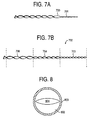
- the stiffening member 700 or stylet is made of substantially flat rectangular stock that can be twisted to provide equal rigidity or bendability in all directions.
- substantially flat in this case, is defined to mean without any major curves that will change the substantially rectangular cross-section of the stiffening member 700.
- the pitch i.e., twists or turns per inch
- the tip 701 shown in Figure 7A is narrowed but still maintained the same pitch as the rest of the stiffening member 700.
- tip 701 of stiffening member or stylet 700 can have different shapes, for example, a flat-shaped tip or a rounded tip. It will also be apparent to one of skill in the art that both ends of the stylet could have, for example, a flat-shaped tip or a rotary-swaged rounded tip.
- the embodiment shown in Figure 7A is meant to be illustrative and not limiting.
- FIG. 7B A side-view of another embodiment of the present invention is shown in Figure 7B .
- a stiffening member 702 having three different pitches is illustrated.
- the proximal portion 703 of stiffening member 702 has the greatest pitch and is thus, the softest portion of stiffening member 702.
- the distal portion 706 has the smallest pitch and consequently, is the stiffest portion of stiffening member 702.
- Mid-section 704 has a pitch that is between the pitch of proximal portion 703 and of distal portion 706. Thus, mid-section 704 is stiffer than proximal portion 703, but softer than distal portion 706. It is to be appreciated that any number of different pitches can be obtained within a single stiffening member 702.
- FIG. 8 a cross-section of another embodiment of the present invention is illustrated.
- a single elongated, substantially rectangular stiffening member 804 is shown within a catheter 800.
- the substantially rectangular shaped member is an elliptical-shaped member 804 that can be twisted, in one embodiment, to provide equal rigidity along any axis.
- the elliptical shape fits within "substantially rectangular" as defined earlier.
- a cross-section of elliptical stiffening member 804 has a first axis that is longer than a second-axis that is perpendicular to the first-axis.
- the first-axis is the "long” dimension and the second-axis is the "short” dimension of substantially rectangular stiffening member 804.
- the portion of stiffening member 804 that is aligned along the first axis provides most of the mechanical strength.
- the diameter of the cross-section of the first-axis can closely approximate or be less than the diameter of the catheter.
- elliptical stiffening member 804 can be formed so that more than half of the lumen area of catheter 800 is available for fluid flow 802.
- a cross-section of stiffening member 804 can also substantially define the cross-sectional area of the stylet. It will be appreciated that an additional treatment, such as a coating (e.g., a hydrogel or TeflonTM ) can be placed around the stiffening member 804. The coating does not substantially increase the diameter or cross-sectional area of the stiffening member 804. In other words, the coating should not dramatically decrease fluid flow area 802.
- a coating e.g., a hydrogel or TeflonTM
- the pitch of elliptically-shaped stiffening member 804 may be varied to change the stiffness of the stylet.
- stiffening member 804 can be twisted at one pitch on its proximal end and another pitch at its distal end to produce different stiffnesses within a single stiffening member 804.
- one end or both ends of elliptically-shaped member 804 may have many different shapes. For instance, one end or both ends can be narrowed to form a tip.
- the tip can have different configurations, for example, a flat-shaped tip or a rounded tip that can be obtained by a rotary swage.
- Fig. 8 is meant to be illustrative and not limiting.
- Figures 9A-C illustrate how the present invention can be defined by how a cross-sectional area of a stylet is a certain percentage of the cross-sectional area of the catheter's lumen. More specifically, Figs. 9A-C illustrate a cross-section of an I-beam embodiment of the present invention relative to the cross-section of the catheter's lumen in which the I-beam embodiment is disposed.
- the internal diameter of the catheter 900 can be 0.035th of an inch, and the axis along the length of the two ends can increase from about 0.012th of an inch in Fig. 9A , to about 0.024th of an inch in Fig. 9B , and then to about 0.030th of an inch in Fig. 9C .
- Figures 9A-C illustrate how the fluid flow area decreases as the cross-sectional area of the stiffening member increases from Figures 9A-C .
- stiffening member 902 has a cross-sectional area that is about 18% of the cross-sectional area of the lumen of catheter 900.
- fluid flow area 903 that is about 82% of the cross-sectional area of the lumen of catheter 900.
- the stiffening member 904 is larger and its cross-section occupies about 27.2% of the cross-sectional area of the lumen of catheter 900.
- the fluid flow area 905 is about 72.8% of the cross-sectional area of the lumen of catheter 900.
- the ends of the I-beam have increased such that the cross-sectional area of the stiffening member 906 has increased to about 38.6% of the cross-sectional area of the lumen of catheter 900.
- the fluid flow area 907 is about 62.4% of the cross-sectional area of the lumen of catheter 900, which is still better than the fluid flow area of the single-element guidewire in the prior art shown in Figure 1 . It will be apparent to one skilled in the art that the percentages given for Figures 9A-C are illustrative and not meant to be limiting.
- an additional treatment such as a coating (e.g., a hydrogel or a TeflonTM or a TeflonTM - type material) can also be placed around each of the stiffening members (902, 904, 906) illustrated in Figures 9A-C , respectively.
- This coating should not substantially increase the cross-sectional area of the stiffening member or decrease dramatically the fluid flow area.
- each of the stiffening members (902, 904, 906) shown in Figs. 9A-C can be twisted and can have varying pitches within a single stiffening member.
- a stiffening member that is shaped like a circular or ellipsoidal O-ring would also fall within the scope of the present invention.
- FIG. 10 A cross-section of an "X-shaped” or “cross-shaped” embodiment of the present invention is illustrated in Figure 10 .
- An "X-shaped" stiffening member 1004 formed of two substantially rectangular elongated members is disposed within catheter 100 with fluid flow area 1005.
- One substantially rectangular elongated member has a long axis 1003 that is at least twice the length of its short axis 1006.
- the second substantially rectangular elongated member also has a long axis 1001 that is at least twice the length of its short axis 1002. It is to be appreciated that long axis 1001 and long axis 1003 and each of their respective short axes (1002, 1006) do not have to be equivalent as shown in Fig. 10 .
- stiffening member 1004 can be twisted at one pitch or several different pitches throughout its entire length.
- an additional treatment such as a coating (e.g., a hydrogel or a TeflonTM or TeflonTM-type material) can be placed around stiffening member 1004.
- the coating should not substantially increase the diameter or cross-sectional area of stiffening member 1004. Thus, the coating should not greatly decrease the fluid flow area 1005.
- a stiffening member such as a stylet
- a medical device such as a PICC.
- the medical device can be, for example, a stent, a cannula, a scope or any other device that uses a stylet or a guidewire. It will be appreciated that numerous modifications may be made in practicing the present invention without departing from scope of the invention, which is defined by the following claims.
Landscapes
- Health & Medical Sciences (AREA)
- Life Sciences & Earth Sciences (AREA)
- Biophysics (AREA)
- Pulmonology (AREA)
- Engineering & Computer Science (AREA)
- Anesthesiology (AREA)
- Biomedical Technology (AREA)
- Heart & Thoracic Surgery (AREA)
- Hematology (AREA)
- Animal Behavior & Ethology (AREA)
- General Health & Medical Sciences (AREA)
- Public Health (AREA)
- Veterinary Medicine (AREA)
- Media Introduction/Drainage Providing Device (AREA)
- Infusion, Injection, And Reservoir Apparatuses (AREA)
Claims (9)
- Dispositif d'accès vasculaire comprenant :un cathéter (500, 600, 800, 900, 1 000) ayant une lumière (504, 511, 513, 603, 605, 609, 802, 903, 905, 907, 1 005) ; etun stylet allongé (502, 510, 512, 602, 604, 608, 702, 804, 902, 904, 906, 1 004) disposé à l'intérieur de la lumière (504, 511, 513, 603, 605, 609, 802, 903, 905, 907, 1 005), dans lequel le stylet (502, 510, 512, 602, 604, 608, 702, 804, 902, 904, 906, 1 004) comprend une partie allongée ayant une section transversale substantiellement rectangulaire et qui s'étend à travers la lumière (504, 511, 513, 603, 605, 609, 802, 903, 905, 907, 1 005) qui, en coupe transversale, se rapproche étroitement d'un diamètre interne de la lumière (504, 511, 513, 603, 605, 609, 802, 903, 905, 907, 1 005) et qui permet au fluide de couler à travers plus que la moitié de la lumière (504, 511, 513, 603, 605, 609, 802, 903, 905, 907, 1 005) autour du stylet (502, 510, 512, 602, 604, 608, 702, 804, 902, 904, 906, 1 004).
- Dispositif d'accès vasculaire selon la revendication 1, dans lequel la section transversale du stylet allongé (502, 510, 512, 602, 604, 608) a une forme rectangulaire substantiellement plate.
- Dispositif d'accès vasculaire selon la revendication 1, dans lequel le stylet allongé (1 004) comprend une seconde section transversale substantiellement rectangulaire pour former une croix avec la première section transversale rectangulaire.
- Dispositif d'accès vasculaire selon la revendication 1, dans lequel la section transversale du stylet allongé (602, 604, 608, 902, 904, 906) est en forme comme un faisceau en I ou comme un os de chien.
- Dispositif d'accès vasculaire selon l'une quelconque des revendications précédentes, dans lequel le stylet allongé (502, 510, 512, 602, 604, 608, 702, 804, 902, 904, 906, 1 004) a un bout resserré (701).
- Dispositif d'accès vasculaire selon l'une quelconque des revendications précédentes, dans lequel le stylet allongé (502, 510, 512, 602, 604, 608, 702, 804, 902, 904, 906, 1 004) inclut un revêtement autour d'un organe de renforcement, dans lequel l'organe de renforcement comprend la plus grande partie du stylet allongé (502, 510, 512, 602, 604, 608, 702, 804, 902, 904, 906, 1 004) et dans lequel le revêtement ne diminue substantiellement pas le flux de fluide autour du stylet (502, 510, 512, 602, 604, 608, 702, 804, 902, 904, 906, 1 004).
- Dispositif d'accès vasculaire selon la revendication 6, dans lequel le revêtement est choisi parmi un groupe se composant d'un hydrogel, d'un polymère de fluorocarbone de tétrafluoroéthylène et d'une résine de propylène éthylène fluoré.
- Dispositif d'accès vasculaire selon l'une quelconque des revendications précédentes, dans lequel l'aire en coupe transversale du stylet allongé (502, 510, 512, 602, 604, 608, 702, 804, 902, 904, 906, 1 004) est dans la fourchette de 16 % à 50 % de l'air en coupe transversale de la lumière (504, 511, 513, 603, 605, 609, 802, 903, 905, 907, 1 005).
- Dispositif d'accès vasculaire selon l'une quelconque des revendications précédentes, dans lequel le stylet allongé (502, 510, 512, 602, 604, 608, 702, 804, 902, 904, 906, 1 004) peut être coupé selon une longueur prédéterminée sans compromettre, changer ou détruire son intégrité structurelle.
Applications Claiming Priority (2)
| Application Number | Priority Date | Filing Date | Title |
|---|---|---|---|
| US772399 | 1996-12-23 | ||
| US08/772,399 US6059771A (en) | 1996-12-23 | 1996-12-23 | Stiffening member to increase fluid flow within a medical device |
Publications (2)
| Publication Number | Publication Date |
|---|---|
| EP0850656A1 EP0850656A1 (fr) | 1998-07-01 |
| EP0850656B1 true EP0850656B1 (fr) | 2004-09-29 |
Family
ID=25094939
Family Applications (1)
| Application Number | Title | Priority Date | Filing Date |
|---|---|---|---|
| EP97310499A Expired - Lifetime EP0850656B1 (fr) | 1996-12-23 | 1997-12-23 | Elément de raidissement pour augmenter le flux d'un liquide dans un dispositif médical |
Country Status (8)
| Country | Link |
|---|---|
| US (2) | US6059771A (fr) |
| EP (1) | EP0850656B1 (fr) |
| JP (1) | JPH10216236A (fr) |
| CN (1) | CN1191756A (fr) |
| AU (1) | AU726407B2 (fr) |
| CA (1) | CA2225440C (fr) |
| DE (1) | DE69730936T2 (fr) |
| ES (1) | ES2229322T3 (fr) |
Families Citing this family (54)
| Publication number | Priority date | Publication date | Assignee | Title |
|---|---|---|---|---|
| CA2297122A1 (fr) | 1997-07-24 | 1999-02-04 | James F. Mcguckin, Jr. | Catheter de dialyse a tunnel central fixe dote d'une gaine separable facultative |
| IE20010244A1 (en) * | 2000-04-28 | 2002-04-03 | Medtronic Inc | Occlusion resistant medical catheter with flexible core |
| JP2002078802A (ja) * | 2000-09-07 | 2002-03-19 | Asahi Intecc Co Ltd | カテーテル |
| US8323228B2 (en) | 2007-04-12 | 2012-12-04 | Rex Medical L.P. | Dialysis catheter |
| US7011645B2 (en) | 2001-01-09 | 2006-03-14 | Rex Medical, L.P. | Dialysis catheter |
| US6858019B2 (en) * | 2001-01-09 | 2005-02-22 | Rex Medical, L.P. | Dialysis catheter and methods of insertion |
| US7097635B2 (en) * | 2001-01-09 | 2006-08-29 | Rex Medical, L.P. | Guidewire retrieval member for catheter insertion |
| US6986752B2 (en) * | 2001-01-09 | 2006-01-17 | Rex Medical, Lp | Peritoneal dialysis catheter and insertion method |
| US7077829B2 (en) | 2001-01-09 | 2006-07-18 | Rex Medical, L.P. | Dialysis catheter |
| US6685664B2 (en) | 2001-06-08 | 2004-02-03 | Chf Solutions, Inc. | Method and apparatus for ultrafiltration utilizing a long peripheral access venous cannula for blood withdrawal |
| US6758836B2 (en) | 2002-02-07 | 2004-07-06 | C. R. Bard, Inc. | Split tip dialysis catheter |
| US7588581B2 (en) * | 2002-03-26 | 2009-09-15 | Medtronic, Inc. | Placement of chronic micro-catheter device and method |
| US7953497B1 (en) | 2002-08-06 | 2011-05-31 | Boston Scientific Neuromodulation Corporation | Insertion stylet |
| US20040073171A1 (en) * | 2002-10-10 | 2004-04-15 | Rogers Bobby E. | Needle-free valve and catheter assembly |
| US20090165784A1 (en) * | 2007-12-28 | 2009-07-02 | Tyco Healthcare Group Lp | Lubricious intubation device |
| EP1435253B1 (fr) | 2002-12-31 | 2007-01-17 | Abbott Laboratories Vascular Enterprises Limited | Cathéter avec partie plus flexible entre la tige et la pointe distale et procédé de fabrication |
| US7393339B2 (en) | 2003-02-21 | 2008-07-01 | C. R. Bard, Inc. | Multi-lumen catheter with separate distal tips |
| WO2004093655A2 (fr) * | 2003-04-23 | 2004-11-04 | Applied Medical Resources Corporation | Guide metallique helicoidal |
| US20040243095A1 (en) | 2003-05-27 | 2004-12-02 | Shekhar Nimkar | Methods and apparatus for inserting multi-lumen spit-tip catheters into a blood vessel |
| US7641621B2 (en) | 2003-08-25 | 2010-01-05 | Boston Scientific Scimed, Inc. | Elongated intra-lumenal medical device |
| US7658723B2 (en) | 2004-05-27 | 2010-02-09 | Abbott Laboratories | Catheter having plurality of stiffening members |
| US7785439B2 (en) | 2004-09-29 | 2010-08-31 | Abbott Laboratories Vascular Enterprises Limited | Method for connecting a catheter balloon with a catheter shaft of a balloon catheter |
| US7628769B2 (en) * | 2004-05-27 | 2009-12-08 | Abbott Laboratories | Catheter having overlapping stiffening members |
| US7794448B2 (en) | 2004-05-27 | 2010-09-14 | Abbott Laboratories | Multiple lumen catheter and method of making same |
| US7815627B2 (en) * | 2004-05-27 | 2010-10-19 | Abbott Laboratories | Catheter having plurality of stiffening members |
| US7785318B2 (en) | 2004-05-27 | 2010-08-31 | Abbott Laboratories | Catheter having plurality of stiffening members |
| EP1748815B1 (fr) * | 2004-05-27 | 2009-09-16 | Abbott Laboratories | Catheter presentant un premier et un second tube de fil-guide et espace entre ces tubes |
| US8992454B2 (en) | 2004-06-09 | 2015-03-31 | Bard Access Systems, Inc. | Splitable tip catheter with bioresorbable adhesive |
| FR2876919B1 (fr) * | 2004-10-26 | 2007-07-27 | Millipore Corp | Aiguille de maintien comportant des joues de prehension. |
| FR2876923B1 (fr) * | 2004-10-26 | 2007-03-30 | Millipore Corp | Aiguille de prelevement double et procede pour sa realisation. |
| JP4693091B2 (ja) * | 2004-12-21 | 2011-06-01 | 朝日インテック株式会社 | カテーテル及びその製造方法 |
| US20060200190A1 (en) * | 2005-03-02 | 2006-09-07 | Lorenzo Juan A | Embolic coil with twisted wire |
| US20070244413A1 (en) * | 2006-04-12 | 2007-10-18 | Medtronic Vascular, Inc. | Medical guidewire tip construction |
| US8177753B2 (en) * | 2007-06-01 | 2012-05-15 | Arrow International, Inc. | Catheter insertion assembly |
| EP2214765A4 (fr) | 2007-10-17 | 2011-08-10 | Bard Access Systems Inc | Fabrication de cathéters à pointe divisée |
| US8292841B2 (en) | 2007-10-26 | 2012-10-23 | C. R. Bard, Inc. | Solid-body catheter including lateral distal openings |
| US8066660B2 (en) | 2007-10-26 | 2011-11-29 | C. R. Bard, Inc. | Split-tip catheter including lateral distal openings |
| JP5452498B2 (ja) | 2007-11-01 | 2014-03-26 | シー・アール・バード・インコーポレーテッド | 三重管腔端を含むカテーテル組立体 |
| US9579485B2 (en) | 2007-11-01 | 2017-02-28 | C. R. Bard, Inc. | Catheter assembly including a multi-lumen configuration |
| US8317744B2 (en) | 2008-03-27 | 2012-11-27 | St. Jude Medical, Atrial Fibrillation Division, Inc. | Robotic catheter manipulator assembly |
| US8591450B2 (en) | 2010-06-07 | 2013-11-26 | Rex Medical L.P. | Dialysis catheter |
| JP5863790B2 (ja) * | 2011-06-13 | 2016-02-17 | 日星電気株式会社 | ガイドワイヤのための樹脂製チューブ、ガイドワイヤのための樹脂製チューブの製造方法及びガイドワイヤ |
| US9554822B2 (en) * | 2011-09-02 | 2017-01-31 | Abbott Cardiovascular Systems Inc. | Thrombectomy catheter with aspiration and guidewire lumens defining an asymmetrical taper and cutting edge with offset tip |
| US20130096482A1 (en) * | 2011-10-18 | 2013-04-18 | Medtronic Xomed, Inc. | Alternate geometry stylet for ventricular shunt catheter placement |
| USD748252S1 (en) | 2013-02-08 | 2016-01-26 | C. R. Bard, Inc. | Multi-lumen catheter tip |
| JP5896480B2 (ja) * | 2013-10-02 | 2016-03-30 | 朝日インテック株式会社 | ガイドワイヤ |
| JP2015070896A (ja) * | 2013-10-02 | 2015-04-16 | 朝日インテック株式会社 | シャフト及びそのシャフトを用いたガイドワイヤ |
| JP6061341B2 (ja) | 2013-12-06 | 2017-01-18 | 朝日インテック株式会社 | ガイドワイヤ |
| JP5888755B2 (ja) * | 2014-02-24 | 2016-03-22 | 朝日インテック株式会社 | カテーテル |
| WO2016011091A1 (fr) | 2014-07-14 | 2016-01-21 | C. R. Bard, Inc. | Appareils, systèmes et procédés pour introduction de cathéters à pointe divisée ayant des propriétés de raidissement et de guidage améliorées |
| EP2990068A1 (fr) * | 2014-09-01 | 2016-03-02 | Cabinet Cardiologie Champel SA | Dispositif permettant de faciliter l'insertion d'un élément endovasculaire sur un fil de guidage |
| CA3179728A1 (fr) * | 2020-05-27 | 2021-12-02 | Paul M. O'DONNELL | Catheter urinaire multi-flex |
| CN114901340B (zh) | 2020-10-01 | 2024-08-16 | 泰利福医疗公司 | 具有改进的穿引能力的探针 |
| JP7509922B2 (ja) * | 2020-12-22 | 2024-07-02 | 朝日インテック株式会社 | ガイドワイヤ |
Citations (1)
| Publication number | Priority date | Publication date | Assignee | Title |
|---|---|---|---|---|
| JPH0232899B2 (fr) * | 1982-07-31 | 1990-07-24 | Tore Monofuiramento Kk |
Family Cites Families (39)
| Publication number | Priority date | Publication date | Assignee | Title |
|---|---|---|---|---|
| US3620883A (en) * | 1968-09-25 | 1971-11-16 | George S Nalle Jr | Apparatus for extruding plastic netting |
| US3608612A (en) * | 1969-09-10 | 1971-09-28 | Overhead Door Corp | Door operator |
| US3769158A (en) * | 1971-11-24 | 1973-10-30 | Nuclear Fuel Services | End fitting retainer for nuclear fuel assembly |
| US4210323A (en) * | 1978-05-18 | 1980-07-01 | Feather Jack V | Body engaging exercising device |
| US4253462A (en) * | 1979-08-09 | 1981-03-03 | Medtronic, Inc. | Stylet |
| US4498482A (en) * | 1979-12-13 | 1985-02-12 | Medtronic, Inc. | Transvenous pacing lead having improved stylet |
| US4381013A (en) * | 1981-03-19 | 1983-04-26 | Medtronic, Inc. | "J" Stylet wire |
| US4661094A (en) * | 1985-05-03 | 1987-04-28 | Advanced Cardiovascular Systems | Perfusion catheter and method |
| US4732162A (en) * | 1985-10-18 | 1988-03-22 | Martell Medical Products, Inc. | Automatic and position-sensitive syringe and method for nonaspirating or aspirating obtaining of blood samples |
| US4854330A (en) * | 1986-07-10 | 1989-08-08 | Medrad, Inc. | Formed core catheter guide wire assembly |
| US4850960A (en) * | 1987-07-08 | 1989-07-25 | Joseph Grayzel | Diagonally tapered, bevelled tip introducing catheter and sheath and method for insertion |
| US4796642A (en) * | 1987-12-28 | 1989-01-10 | Cordis Leads, Inc. | Pacing lead stylet |
| US4917670A (en) | 1988-03-22 | 1990-04-17 | Hurley Ronald J | Continuous spinal anesthesia administering apparatus and method |
| US4935008A (en) * | 1988-07-20 | 1990-06-19 | Lewis Jr Ronald L | Double lumen introducing needle |
| US5007903A (en) * | 1988-11-22 | 1991-04-16 | Real World Design & Development Company | Syringe adapted to prevent needle sticks |
| US4932939A (en) * | 1989-03-06 | 1990-06-12 | Magre George R | Safety syringe |
| US5254088A (en) * | 1990-02-02 | 1993-10-19 | Ep Technologies, Inc. | Catheter steering mechanism |
| US5273527A (en) * | 1992-05-12 | 1993-12-28 | Ovamed Corporation | Delivery catheter |
| JPH0683726B2 (ja) * | 1990-10-12 | 1994-10-26 | 日本精線株式会社 | カテーテル用ガイドワイヤ |
| US5238005A (en) * | 1991-11-18 | 1993-08-24 | Intelliwire, Inc. | Steerable catheter guidewire |
| ZA931943B (en) * | 1992-03-30 | 1993-11-16 | Pameda Nv | Inflatable shaft catheter |
| US5413560A (en) * | 1992-03-30 | 1995-05-09 | Pameda N.V. | Method of rapid catheter exchange |
| ZA932947B (en) * | 1992-04-28 | 1993-10-27 | Schering Plough Healthcare | Applicator for semisolid medications |
| US5437288A (en) * | 1992-09-04 | 1995-08-01 | Mayo Foundation For Medical Education And Research | Flexible catheter guidewire |
| US5299580A (en) * | 1992-10-09 | 1994-04-05 | Scimed Life Systems, Inc. | Guidewire with safety ribbon with substantially axially symmetric flexibility |
| US5348541A (en) * | 1993-05-05 | 1994-09-20 | Lyell Mark S | Suprapubic catheter placement apparatus (lyell sound) |
| US5357961A (en) * | 1993-05-12 | 1994-10-25 | Hdc Corporation | Catheter guidewire and flushing apparatus and method of insertion |
| US5382238A (en) * | 1993-05-20 | 1995-01-17 | Quinton Instrument Company | Catheter stiffeners |
| US5437632A (en) * | 1993-06-02 | 1995-08-01 | Target Therapeutics, Inc. | Variable stiffness balloon catheter |
| US5370640A (en) * | 1993-07-01 | 1994-12-06 | Kolff; Jack | Intracorporeal catheter placement apparatus and method |
| US5395328A (en) * | 1994-01-19 | 1995-03-07 | Daig Corporation | Steerable catheter tip having an X-shaped lumen |
| US5498249A (en) * | 1994-03-24 | 1996-03-12 | Radius International, Inc. | Catheter stylet |
| US5460614A (en) * | 1994-08-15 | 1995-10-24 | Cordis Corporation | Guidewire trapping catheter |
| US5498251A (en) * | 1994-11-29 | 1996-03-12 | Dalton; Michael J. | Tissue perfusion catheter |
| JP3318921B2 (ja) * | 1995-02-21 | 2002-08-26 | ニプロ株式会社 | スタイレットおよびスタイレット用コネクター |
| US5611345A (en) * | 1995-04-24 | 1997-03-18 | Hibbeln; John F. | Medical instrument with improved ultrasonic visibility |
| US5676653A (en) * | 1995-06-27 | 1997-10-14 | Arrow International Investment Corp. | Kink-resistant steerable catheter assembly |
| EP0904127B1 (fr) * | 1996-05-17 | 2005-02-23 | Biosense Webster, Inc. | Catheter a autoalignement |
| US5826576A (en) * | 1996-08-08 | 1998-10-27 | Medtronic, Inc. | Electrophysiology catheter with multifunction wire and method for making |
-
1996
- 1996-12-23 US US08/772,399 patent/US6059771A/en not_active Expired - Lifetime
-
1997
- 1997-12-22 CA CA002225440A patent/CA2225440C/fr not_active Expired - Fee Related
- 1997-12-22 JP JP9365812A patent/JPH10216236A/ja active Pending
- 1997-12-22 AU AU49213/97A patent/AU726407B2/en not_active Ceased
- 1997-12-23 EP EP97310499A patent/EP0850656B1/fr not_active Expired - Lifetime
- 1997-12-23 DE DE69730936T patent/DE69730936T2/de not_active Expired - Fee Related
- 1997-12-23 CN CN97129753A patent/CN1191756A/zh active Pending
- 1997-12-23 ES ES97310499T patent/ES2229322T3/es not_active Expired - Lifetime
-
2000
- 2000-02-01 US US09/495,619 patent/US6770038B2/en not_active Expired - Lifetime
Patent Citations (1)
| Publication number | Priority date | Publication date | Assignee | Title |
|---|---|---|---|---|
| JPH0232899B2 (fr) * | 1982-07-31 | 1990-07-24 | Tore Monofuiramento Kk |
Also Published As
| Publication number | Publication date |
|---|---|
| CN1191756A (zh) | 1998-09-02 |
| AU726407B2 (en) | 2000-11-09 |
| JPH10216236A (ja) | 1998-08-18 |
| AU4921397A (en) | 1998-06-25 |
| US20020065486A1 (en) | 2002-05-30 |
| DE69730936T2 (de) | 2005-10-06 |
| EP0850656A1 (fr) | 1998-07-01 |
| US6059771A (en) | 2000-05-09 |
| US6770038B2 (en) | 2004-08-03 |
| DE69730936D1 (de) | 2004-11-04 |
| ES2229322T3 (es) | 2005-04-16 |
| CA2225440A1 (fr) | 1998-06-23 |
| CA2225440C (fr) | 2002-03-26 |
Similar Documents
| Publication | Publication Date | Title |
|---|---|---|
| EP0850656B1 (fr) | Elément de raidissement pour augmenter le flux d'un liquide dans un dispositif médical | |
| AU2013207563B2 (en) | Guidewire with highly flexible tip | |
| KR102770735B1 (ko) | 일체형 코일 혈관 장치 | |
| CN101107023B (zh) | 导管插入装置 | |
| US8382739B2 (en) | Composite medical device and method of forming | |
| EP0850657B1 (fr) | Stylet thermiquement ramollissable | |
| JP2022553959A (ja) | 迅速挿入型中心静脈カテーテル及びその方法 | |
| US7896861B2 (en) | Catheter with a pre-shaped distal tip | |
| US20060253102A1 (en) | Non-expandable transluminal access sheath | |
| JPH07148264A (ja) | マイクロカテーテル | |
| CN112546402B (zh) | 能够弯曲的导丝 | |
| CN106456942B (zh) | 具有改善刚度的抗扭结导丝 | |
| CA2102250A1 (fr) | Fil-guide de catheter flexible | |
| CN102202717B (zh) | 能通过具有支管的解剖结构的导航引导线 | |
| WO2010075000A1 (fr) | Gaine d'intubateur à rigidité variable dotée d'une zone de transition | |
| US20250195833A1 (en) | Variable radius braid for a medical device | |
| WO2010060889A1 (fr) | Microcathéter | |
| WO2024116319A1 (fr) | Dispositif médical et son procédé de fabrication | |
| MXPA98000181A (en) | A member of reinforcement to increase the deflated flow within a med device | |
| JP7800811B2 (ja) | 可変断面形状を有するカテーテル編組ワイヤ | |
| AU2023309003A1 (en) | Coronary/vascular wire | |
| EP4598615A1 (fr) | Cathéter à surface de contact réduite | |
| JPH0556152U (ja) | カテーテル用ガイドワイヤ |
Legal Events
| Date | Code | Title | Description |
|---|---|---|---|
| PUAI | Public reference made under article 153(3) epc to a published international application that has entered the european phase |
Free format text: ORIGINAL CODE: 0009012 |
|
| AK | Designated contracting states |
Kind code of ref document: A1 Designated state(s): BE CH DE ES FR GB IT LI SE |
|
| AX | Request for extension of the european patent |
Free format text: AL;LT;LV;MK;RO;SI |
|
| 17P | Request for examination filed |
Effective date: 19981126 |
|
| AKX | Designation fees paid |
Free format text: BE CH DE ES FR GB IT LI SE |
|
| RBV | Designated contracting states (corrected) |
Designated state(s): BE CH DE ES FR GB IT LI SE |
|
| TPAD | Observations filed by third parties |
Free format text: ORIGINAL CODE: EPIDOS TIPA |
|
| 17Q | First examination report despatched |
Effective date: 20020211 |
|
| GRAP | Despatch of communication of intention to grant a patent |
Free format text: ORIGINAL CODE: EPIDOSNIGR1 |
|
| GRAS | Grant fee paid |
Free format text: ORIGINAL CODE: EPIDOSNIGR3 |
|
| GRAA | (expected) grant |
Free format text: ORIGINAL CODE: 0009210 |
|
| AK | Designated contracting states |
Kind code of ref document: B1 Designated state(s): BE CH DE ES FR GB IT LI SE |
|
| REG | Reference to a national code |
Ref country code: GB Ref legal event code: FG4D |
|
| REG | Reference to a national code |
Ref country code: CH Ref legal event code: EP |
|
| REF | Corresponds to: |
Ref document number: 69730936 Country of ref document: DE Date of ref document: 20041104 Kind code of ref document: P |
|
| REG | Reference to a national code |
Ref country code: SE Ref legal event code: TRGR |
|
| REG | Reference to a national code |
Ref country code: CH Ref legal event code: NV Representative=s name: E. BLUM & CO. PATENTANWAELTE |
|
| REG | Reference to a national code |
Ref country code: ES Ref legal event code: FG2A Ref document number: 2229322 Country of ref document: ES Kind code of ref document: T3 |
|
| PLBE | No opposition filed within time limit |
Free format text: ORIGINAL CODE: 0009261 |
|
| STAA | Information on the status of an ep patent application or granted ep patent |
Free format text: STATUS: NO OPPOSITION FILED WITHIN TIME LIMIT |
|
| ET | Fr: translation filed | ||
| 26N | No opposition filed |
Effective date: 20050630 |
|
| REG | Reference to a national code |
Ref country code: CH Ref legal event code: PFA Owner name: JOHNSON & JOHNSON MEDICAL, INC. Free format text: JOHNSON & JOHNSON MEDICAL, INC.#2500 ARBROOK BOULEVARD#ARLINGTON, TEXAS 76014 (US) -TRANSFER TO- JOHNSON & JOHNSON MEDICAL, INC.#2500 ARBROOK BOULEVARD#ARLINGTON, TEXAS 76014 (US) |
|
| PGFP | Annual fee paid to national office [announced via postgrant information from national office to epo] |
Ref country code: CH Payment date: 20081230 Year of fee payment: 12 |
|
| PGFP | Annual fee paid to national office [announced via postgrant information from national office to epo] |
Ref country code: SE Payment date: 20081205 Year of fee payment: 12 Ref country code: IT Payment date: 20081224 Year of fee payment: 12 |
|
| PGFP | Annual fee paid to national office [announced via postgrant information from national office to epo] |
Ref country code: FR Payment date: 20081212 Year of fee payment: 12 Ref country code: ES Payment date: 20090120 Year of fee payment: 12 |
|
| PGFP | Annual fee paid to national office [announced via postgrant information from national office to epo] |
Ref country code: DE Payment date: 20081219 Year of fee payment: 12 |
|
| PGFP | Annual fee paid to national office [announced via postgrant information from national office to epo] |
Ref country code: GB Payment date: 20081217 Year of fee payment: 12 |
|
| PGFP | Annual fee paid to national office [announced via postgrant information from national office to epo] |
Ref country code: BE Payment date: 20090119 Year of fee payment: 12 |
|
| BERE | Be: lapsed |
Owner name: *JOHNSON & JOHNSON MEDICAL INC. Effective date: 20091231 |
|
| EUG | Se: european patent has lapsed | ||
| REG | Reference to a national code |
Ref country code: CH Ref legal event code: PL |
|
| GBPC | Gb: european patent ceased through non-payment of renewal fee |
Effective date: 20091223 |
|
| REG | Reference to a national code |
Ref country code: FR Ref legal event code: ST Effective date: 20100831 |
|
| PG25 | Lapsed in a contracting state [announced via postgrant information from national office to epo] |
Ref country code: LI Free format text: LAPSE BECAUSE OF NON-PAYMENT OF DUE FEES Effective date: 20091231 Ref country code: FR Free format text: LAPSE BECAUSE OF NON-PAYMENT OF DUE FEES Effective date: 20091231 Ref country code: CH Free format text: LAPSE BECAUSE OF NON-PAYMENT OF DUE FEES Effective date: 20091231 Ref country code: BE Free format text: LAPSE BECAUSE OF NON-PAYMENT OF DUE FEES Effective date: 20091231 |
|
| PG25 | Lapsed in a contracting state [announced via postgrant information from national office to epo] |
Ref country code: DE Free format text: LAPSE BECAUSE OF NON-PAYMENT OF DUE FEES Effective date: 20100701 |
|
| PG25 | Lapsed in a contracting state [announced via postgrant information from national office to epo] |
Ref country code: GB Free format text: LAPSE BECAUSE OF NON-PAYMENT OF DUE FEES Effective date: 20091223 |
|
| PG25 | Lapsed in a contracting state [announced via postgrant information from national office to epo] |
Ref country code: IT Free format text: LAPSE BECAUSE OF NON-PAYMENT OF DUE FEES Effective date: 20091223 |
|
| REG | Reference to a national code |
Ref country code: ES Ref legal event code: FD2A Effective date: 20110405 |
|
| PG25 | Lapsed in a contracting state [announced via postgrant information from national office to epo] |
Ref country code: SE Free format text: LAPSE BECAUSE OF NON-PAYMENT OF DUE FEES Effective date: 20091224 |
|
| PG25 | Lapsed in a contracting state [announced via postgrant information from national office to epo] |
Ref country code: ES Free format text: LAPSE BECAUSE OF NON-PAYMENT OF DUE FEES Effective date: 20110323 |
|
| PG25 | Lapsed in a contracting state [announced via postgrant information from national office to epo] |
Ref country code: ES Free format text: LAPSE BECAUSE OF NON-PAYMENT OF DUE FEES Effective date: 20091224 |