EP0850687A2 - Voriichtung zur Feststoffbehandlung in einem Wirbelschichtbett und deren Verwendung - Google Patents
Voriichtung zur Feststoffbehandlung in einem Wirbelschichtbett und deren Verwendung Download PDFInfo
- Publication number
- EP0850687A2 EP0850687A2 EP97403156A EP97403156A EP0850687A2 EP 0850687 A2 EP0850687 A2 EP 0850687A2 EP 97403156 A EP97403156 A EP 97403156A EP 97403156 A EP97403156 A EP 97403156A EP 0850687 A2 EP0850687 A2 EP 0850687A2
- Authority
- EP
- European Patent Office
- Prior art keywords
- particles
- treatment
- fluidized bed
- enclosure
- fluid
- Prior art date
- Legal status (The legal status is an assumption and is not a legal conclusion. Google has not performed a legal analysis and makes no representation as to the accuracy of the status listed.)
- Ceased
Links
Images


Classifications
-
- C—CHEMISTRY; METALLURGY
- C10—PETROLEUM, GAS OR COKE INDUSTRIES; TECHNICAL GASES CONTAINING CARBON MONOXIDE; FUELS; LUBRICANTS; PEAT
- C10G—CRACKING HYDROCARBON OILS; PRODUCTION OF LIQUID HYDROCARBON MIXTURES, e.g. BY DESTRUCTIVE HYDROGENATION, OLIGOMERISATION, POLYMERISATION; RECOVERY OF HYDROCARBON OILS FROM OIL-SHALE, OIL-SAND, OR GASES; REFINING MIXTURES MAINLY CONSISTING OF HYDROCARBONS; REFORMING OF NAPHTHA; MINERAL WAXES
- C10G11/00—Catalytic cracking, in the absence of hydrogen, of hydrocarbon oils
- C10G11/14—Catalytic cracking, in the absence of hydrogen, of hydrocarbon oils with preheated moving solid catalysts
- C10G11/18—Catalytic cracking, in the absence of hydrogen, of hydrocarbon oils with preheated moving solid catalysts according to the "fluidised-bed" technique
-
- B—PERFORMING OPERATIONS; TRANSPORTING
- B01—PHYSICAL OR CHEMICAL PROCESSES OR APPARATUS IN GENERAL
- B01J—CHEMICAL OR PHYSICAL PROCESSES, e.g. CATALYSIS OR COLLOID CHEMISTRY; THEIR RELEVANT APPARATUS
- B01J19/00—Chemical, physical or physico-chemical processes in general; Their relevant apparatus
- B01J19/32—Packing elements in the form of grids or built-up elements for forming a unit or module inside the apparatus for mass or heat transfer
-
- B—PERFORMING OPERATIONS; TRANSPORTING
- B01—PHYSICAL OR CHEMICAL PROCESSES OR APPARATUS IN GENERAL
- B01J—CHEMICAL OR PHYSICAL PROCESSES, e.g. CATALYSIS OR COLLOID CHEMISTRY; THEIR RELEVANT APPARATUS
- B01J8/00—Chemical or physical processes in general, conducted in the presence of fluids and solid particles; Apparatus for such processes
- B01J8/08—Chemical or physical processes in general, conducted in the presence of fluids and solid particles; Apparatus for such processes with moving particles
- B01J8/12—Chemical or physical processes in general, conducted in the presence of fluids and solid particles; Apparatus for such processes with moving particles moved by gravity in a downward flow
-
- B—PERFORMING OPERATIONS; TRANSPORTING
- B01—PHYSICAL OR CHEMICAL PROCESSES OR APPARATUS IN GENERAL
- B01J—CHEMICAL OR PHYSICAL PROCESSES, e.g. CATALYSIS OR COLLOID CHEMISTRY; THEIR RELEVANT APPARATUS
- B01J8/00—Chemical or physical processes in general, conducted in the presence of fluids and solid particles; Apparatus for such processes
- B01J8/18—Chemical or physical processes in general, conducted in the presence of fluids and solid particles; Apparatus for such processes with fluidised particles
- B01J8/24—Chemical or physical processes in general, conducted in the presence of fluids and solid particles; Apparatus for such processes with fluidised particles according to "fluidised-bed" technique
- B01J8/34—Chemical or physical processes in general, conducted in the presence of fluids and solid particles; Apparatus for such processes with fluidised particles according to "fluidised-bed" technique with stationary packing material in the fluidised bed, e.g. bricks, wire rings, baffles
-
- C—CHEMISTRY; METALLURGY
- C10—PETROLEUM, GAS OR COKE INDUSTRIES; TECHNICAL GASES CONTAINING CARBON MONOXIDE; FUELS; LUBRICANTS; PEAT
- C10G—CRACKING HYDROCARBON OILS; PRODUCTION OF LIQUID HYDROCARBON MIXTURES, e.g. BY DESTRUCTIVE HYDROGENATION, OLIGOMERISATION, POLYMERISATION; RECOVERY OF HYDROCARBON OILS FROM OIL-SHALE, OIL-SAND, OR GASES; REFINING MIXTURES MAINLY CONSISTING OF HYDROCARBONS; REFORMING OF NAPHTHA; MINERAL WAXES
- C10G11/00—Catalytic cracking, in the absence of hydrogen, of hydrocarbon oils
- C10G11/14—Catalytic cracking, in the absence of hydrogen, of hydrocarbon oils with preheated moving solid catalysts
- C10G11/18—Catalytic cracking, in the absence of hydrogen, of hydrocarbon oils with preheated moving solid catalysts according to the "fluidised-bed" technique
- C10G11/182—Regeneration
-
- B—PERFORMING OPERATIONS; TRANSPORTING
- B01—PHYSICAL OR CHEMICAL PROCESSES OR APPARATUS IN GENERAL
- B01J—CHEMICAL OR PHYSICAL PROCESSES, e.g. CATALYSIS OR COLLOID CHEMISTRY; THEIR RELEVANT APPARATUS
- B01J2208/00—Processes carried out in the presence of solid particles; Reactors therefor
- B01J2208/00796—Details of the reactor or of the particulate material
- B01J2208/00823—Mixing elements
- B01J2208/00831—Stationary elements
- B01J2208/0084—Stationary elements inside the bed, e.g. baffles
-
- B—PERFORMING OPERATIONS; TRANSPORTING
- B01—PHYSICAL OR CHEMICAL PROCESSES OR APPARATUS IN GENERAL
- B01J—CHEMICAL OR PHYSICAL PROCESSES, e.g. CATALYSIS OR COLLOID CHEMISTRY; THEIR RELEVANT APPARATUS
- B01J2219/00—Chemical, physical or physico-chemical processes in general; Their relevant apparatus
- B01J2219/32—Details relating to packing elements in the form of grids or built-up elements for forming a unit of module inside the apparatus for mass or heat transfer
- B01J2219/322—Basic shape of the elements
- B01J2219/32203—Sheets
- B01J2219/32206—Flat sheets
-
- B—PERFORMING OPERATIONS; TRANSPORTING
- B01—PHYSICAL OR CHEMICAL PROCESSES OR APPARATUS IN GENERAL
- B01J—CHEMICAL OR PHYSICAL PROCESSES, e.g. CATALYSIS OR COLLOID CHEMISTRY; THEIR RELEVANT APPARATUS
- B01J2219/00—Chemical, physical or physico-chemical processes in general; Their relevant apparatus
- B01J2219/32—Details relating to packing elements in the form of grids or built-up elements for forming a unit of module inside the apparatus for mass or heat transfer
- B01J2219/322—Basic shape of the elements
- B01J2219/32203—Sheets
- B01J2219/3221—Corrugated sheets
-
- B—PERFORMING OPERATIONS; TRANSPORTING
- B01—PHYSICAL OR CHEMICAL PROCESSES OR APPARATUS IN GENERAL
- B01J—CHEMICAL OR PHYSICAL PROCESSES, e.g. CATALYSIS OR COLLOID CHEMISTRY; THEIR RELEVANT APPARATUS
- B01J2219/00—Chemical, physical or physico-chemical processes in general; Their relevant apparatus
- B01J2219/32—Details relating to packing elements in the form of grids or built-up elements for forming a unit of module inside the apparatus for mass or heat transfer
- B01J2219/322—Basic shape of the elements
- B01J2219/32203—Sheets
- B01J2219/32213—Plurality of essentially parallel sheets
-
- B—PERFORMING OPERATIONS; TRANSPORTING
- B01—PHYSICAL OR CHEMICAL PROCESSES OR APPARATUS IN GENERAL
- B01J—CHEMICAL OR PHYSICAL PROCESSES, e.g. CATALYSIS OR COLLOID CHEMISTRY; THEIR RELEVANT APPARATUS
- B01J2219/00—Chemical, physical or physico-chemical processes in general; Their relevant apparatus
- B01J2219/32—Details relating to packing elements in the form of grids or built-up elements for forming a unit of module inside the apparatus for mass or heat transfer
- B01J2219/322—Basic shape of the elements
- B01J2219/32203—Sheets
- B01J2219/32224—Sheets characterised by the orientation of the sheet
- B01J2219/32227—Vertical orientation
-
- B—PERFORMING OPERATIONS; TRANSPORTING
- B01—PHYSICAL OR CHEMICAL PROCESSES OR APPARATUS IN GENERAL
- B01J—CHEMICAL OR PHYSICAL PROCESSES, e.g. CATALYSIS OR COLLOID CHEMISTRY; THEIR RELEVANT APPARATUS
- B01J2219/00—Chemical, physical or physico-chemical processes in general; Their relevant apparatus
- B01J2219/32—Details relating to packing elements in the form of grids or built-up elements for forming a unit of module inside the apparatus for mass or heat transfer
- B01J2219/324—Composition or microstructure of the elements
- B01J2219/32466—Composition or microstructure of the elements comprising catalytically active material
Definitions
- the present invention relates to the operations of treatment of cracked catalyst particles catalytic in the fluid state, and more particularly the stripping and regeneration of the catalyst. More specifically, it relates to a device and a process for treating, with a fluid circulating against the current, the particles of catalyst in a dense fluidized bed, in particular to eliminate the pollutants entrained with these particles and / or adsorbed thereon.
- Catalyst particles are rapidly deactivated during the short time they are in contact with the charge, mainly due to adsorption of hydrocarbons, as well as a deposit of coke and other contaminants on their active sites . It is therefore necessary to continuously stripped the deactivated grains of catalyst, to recover the adsorbed hydrocarbons and entrained in the empty volumes separating these grains, then to regenerate these grains of catalyst, also continuously, by controlled combustion of coke, in a regeneration section with one or more stages. The catalyst grains are then recycled to the reaction zone.
- These two treatment operations namely stripping and regeneration, are carried out in a dense fluidized bed, that is to say with a density of between 400 and 800 kg / m 3 .
- stripping is carried out in an enclosure located at the outlet of the column reaction, whether ascending or descending, after separation of effluents from the reaction zone.
- stripping operates in dense fluidized phase.
- a gaseous fluid of preferably very polar (water vapor for example), is injected at the base of the enclosure and backwashing the suspension of deactivated grains of catalyst. It allows the displacement and recovery of hydrocarbons, which are either entrained in the empty spaces left between the grains of deactivated catalysts, or adsorbed to their area.
- the stripped catalyst grains are evacuated by an outlet located at the base of the enclosure.
- the residence time of the catalyst particles in the stripper must be as homogeneous as possible. Indeed, if the catalyst remains for an insufficient time in the stripper, an excess of hydrocarbons remains deposited at its surface and is then sent to the regenerator. This leads at too high a regeneration temperature, harmful to correct operation of the unit, to the detriment of the quantity recoverable hydrocarbons recovered in the area of splitting.
- Regeneration usually takes place against the current, within a dense fluidized bed, at the top of which is introduced the coked catalyst to be regenerated and at the base of which a gas of combustion rich in oxygen, for example air, is allowed by a blower.
- the residence time of the particles of catalyst in the regeneration enclosure should be the most homogeneous possible.
- U.S. Patent 2,781,301 proposes, in a oil purification chamber circulating against the current adsorbent particles, introduce a plurality of vertical internal partitions.
- the aim is to decrease in back-mixing phenomena (trend of particles to be carried upwards by the fluid ascending), as well as better speed control passage.
- U.S. Patent 2,481,439 provides an enclosure for stripping comprising a plurality of linings spaced apart from each other, each of these linings consisting of grids stacked one at a time above others and welded so as to form vertical cells.
- the spaces between these linings turn out to be areas of privileged turbulence, where randomly produce vortices and back-mixing.
- the catalyst particles do not progress so not continuously and uniformly, which results in a lack of uniformity of the residence time of the particles in the stripping enclosure.
- the present object of the invention is to provide a device and a method for the treatment of fluidized solid particles, which allow a homogenization of the residence time of these particles in the treatment area, while achieving intimate contact between the solid and the fluid treatment.
- This device makes it possible to achieve the aforementioned objectives.
- independent treatment cells created by the interposition of vertical partitions continuous extend over most of the length of the dense fluidized bed of particles to be treated. These cells therefore have a height / diameter ratio high, which is much higher than that of pregnant classics. In this way, the recirculation currents and the retromix, which are all the more important as this ratio is low, are very clearly attenuated: within each cell, there is a piston type flow, which allows all solid particles to progress by uniformly.
- the segregation between the rising vapor and the solid descending is avoided, to the extent that, unlike the techniques of the prior art, the elementary processing cells of the invention are comparable to as many empty speakers.
- the invention avoids therefore the use of inclined obstacles on the walls from which the catalyst is likely to accumulate.
- the device according to the present invention is not subject erosion by the flow of catalyst particles, unlike many devices of the prior art.
- this process being characterized in that, during the step treatment, catalyst particles and said fluid gases pass through a plurality of cells elementary processing, independent of each others, defined inside said enclosure by a partition of continuous vertical partitions, which divide the dense fluidized bed in a plurality of fluidized beds dense contiguous, flowing up and down so independent from each other.
- the term “dense fluidized bed” means a fluidized bed whose density is between 400 and 800 kg / m 3 .
- Vertical partitions according to the invention can extend over a height between 50 and 90%, and preferably between 60 and 80% of the height of the bed dense fluidized.
- the number of cells of elementary processing defined by the partitions vertical according to the invention is such that the ratio between their height and their hydraulic diameter is included between 3 and 10 and preferably between 5 and 7.
- this number of elementary processing cells is between 2 and 50, preferably between 3 and 40 and, even more preferably, between 5 and 20.
- At least one means of homogeneous particle distribution is arranged above the partition partition vertical.
- Such distribution means can be placed either at the outlet of the conduit for introducing the catalytic particles, either in the dense fluidized bed itself, and they can be used alternately or additionally.
- At least one means of distribution homogeneous treatment fluid can be arranged underneath of the partitioning of vertical partitions. This or these distribution means can be placed either at level of the outlet of the fluid supply line, either in the dense fluidized bed, and they can be used alternately or in addition.
- the particles and the stripping fluid are distributed so uniform over the entire section of the stripping chamber.
- Each elementary cell is thus well supplied with both in particles and in fluid. Stripping within each cell is then particularly satisfactory, due to the piston type flow which reign.
- these distribution means homogeneous are likely are able to orient to their exit the catalyst particles or the fluid in two different directions. About 50% of the particles are deviated in a first direction and the remaining 50% are deflected in a second direction forming an angle of 10 to 90 degrees with the first direction. It is the same for the fluid above its supply line.
- the distribution means can be constituted by the assembly of pleated sheets cut transversely by compared to their plans.
- These pleated sheets can be perforated, striated or rough, and are assembled in a way such that the pleat edge of each sheet forms an angle substantially 45 to 135 degrees with the pleat edge of the adjacent sheet. According to a particularly preferred mode of invention, this angle is 90 degrees, thus defining networks of channels crossed at right angles. These crosses advantageously allow close contact between the fluid and particles inside the lining.
- the arrangement of the sheets promotes distribution homogeneous particles or fluid.
- 50% of catalyst particles (or fluid) are diverted to each intersection formed by the pleat edges of a first sheet with one second pleat edges adjacent sheet metal.
- static mixers such as those sold by Companies named Sulzer-SMV or Kenics, although not intended for such an application, can be adapted and modified to allow a homogeneous distribution of particles or fluid.
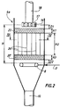
- the catalytic cracking device by the FCC process shown schematically in Figure 1 is of a type known per se. It basically includes a column 1, said load lifter, powered at its base, by the line 2, in charge to be treated and, via line 3, in particles a cracking catalyst.
- a lifting gas for example water vapor, is introduced into column 1 by the line 35.
- Column 1 opens at its top into a capacity 4, where the cracked charge is separated and at the base of which the deactivated particles of catalyst are stripped in a stripping chamber 4 a .
- the enclosure of a stripping 4 is eccentric with respect to the column.
- this enclosure can take other forms and positions.
- this enclosure can be concentric with the column, which requires a suitable drawing of the elements.
- the treated charge is separated in a cyclone 5, which is housed in capacity 4, at the top of which is provided an evacuation line 6 for the cracked charge, while deactivated particles move by gravity to the stripping chamber 4a.
- Line 7 supplies fluid stripping, usually steam, fluidizing gas injectors or diffusers 8 arranged regularly at the base of the stripping chamber 4a. The stripping is therefore carried out in a dense fluidized bed, against the current particles.
- the deactivated particles of catalyst thus stripped are discharged at the base of the stripping chamber 4a towards a regenerator 9, via a conduit 10, on which is provided with a control valve 11.
- the regenerator 9 the coke deposited on the particles of catalyst is burned with air, injected at the base of the regenerator through a line 12, which supplies injectors 13 regularly spaced.
- Catalyst particles treated, entrained by the flue gas, are separated by cyclones 14, from where the combustion gas is discharged by a line 15, while the catalyst particles are discharged to the base of regenerator 9, from where they are recycled through line 3, fitted with a regulation 16, towards the elevator supply 1.
- the device according to the invention can be used in the stripping enclosure 4a of Figure 1.
- This enclosure 4a comprises at its top a conduit 18 allowing the introduction of particles of catalyst deactivated to stripper and, at its base, a line 7 supplying diffusers 8 with a gaseous fluid of stripping.
- a dense fluidized bed of catalyst therefore extends over a height H of the enclosure, between the conduit 18 of introduction particles and the fluid supply line 7.
- a first means of homogeneous distribution of the catalyst descending is provided at the outlet of conduit 18.
- This means is constituted by an annular distributor 17, which distributes the particles through lateral openings 19.
- a second means 20 for homogeneous distribution of the particles is disposed within the dense fluidized bed itself and extends over a height H 1 of the stripping enclosure.
- the distance D 1 is for example equal to 0.1H, where H is the total height of the dense fluidized bed, but can be between 0.05H and 0.2H.
- the height H 1 is for example equal to 0.1H, but can be between 0.05H and 0.2H.
- the distribution means 20 homogeneous placed in the dense fluidized bed consists of pleated sheets cut transversely to their plan. These pleated sheets are assembled in such a way that the edge of the pleat 22 of each sheet forms an angle of substantially 90 degrees with the pleat edge 22 'of the adjacent sheet metal. Thus, the folds of each sheet intersect with the folds of the adjacent sheet metal and constitute cells forming a network of crossed channels 23, 24.
- the cell section is chosen to avoid any particle obstruction phenomenon.
- the corrugated sheets are welded to each other at the level of the pleat edge 22, 22 '.
- Catalyst particles penetrate and are guided in channels 23, 24.
- the arrangement of the channels allows deflect the particles at each intersection formed by the folds of a first sheet with the folds of a second adjacent sheet, thus causing a distribution homogeneous catalyst particles.
- a partition of continuous vertical partitions 26 is disposed below the distribution means 20 and extends over a height H 2 of the dense fluidized bed.
- the height H 2 is for example equal to 2H / 3, but it can be between H / 2 and 9H / 10.
- the partitions are shown immediately below the distribution means 20, but they can be spaced therefrom by a distance ranging for example up to 0.1H.
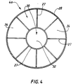
- the partition of vertical partitions is made up of a set of sheets 27 welded either to each other or to the wall 28 circular of the stripping chamber 4a.
- This set defines, in top view, a plurality of cells 30 elementary stripping, first of all an area central 32 substantially concentric with the wall 28 of the stripping enclosure, at the periphery of which extend from truncated angular sectors 34.
- the area central 32, and the truncated angular sectors 34 have substantially equal sections.
- the sheets welded to the walls of the stripping chamber are arranged along diameters thereof, so that the elementary stripping cells are parts of the stripping enclosure.
- a means 20 'of uniform distribution of the stripping fluid is inserted between the lower end of the partitions vertical 26 and diffusers 8 of said fluid. It is similar to means 20 of homogeneous distribution of particles to be stripped, shown in Figure 3, and it does will therefore not be described again.
- This means for distributing the stripping fluid is disposed at a distance D 2 from the fluid supply line, and it further extends over a height H 3 of the stripping enclosure.
- the distance D 2 is for example equal to 0.1H, but it can be between 0.05H and 0.2H.
- the height H 3 is for example equal to H / 10, but it can be between 0.05H and 0.2H.
- the means 20 'of distribution is shown immediately below the partitions vertical, but it can be spaced from a distance of for example up to 0.1H.
- FIG. 5 illustrates the application of the invention to the regeneration enclosure 9 of FIG. 1.
- the particles deactivated catalyst from the containment stripping 4a are directed towards the regeneration enclosure 9 via a conduit 10. It is provided, at the outlet of this conduit, a means of homogeneous distribution of particles, which consists of an extension 36 of the downstream part of the duct, curved upwards. This extension allows the trajectories 37 followed by the catalyst to be distributed along the entire section of enclosure 9.
- the catalyst is maintained in bed conditions dense fluidized, between the conduit 10 and the device supply 13 with regeneration fluid.
- Partition continuous vertical partitions 26, similar to that described with reference to Figures 2 and 4 extends over a substantial fraction of the height H 'of this fluidized bed dense, for example equal to 2H '/ 3 but which can be understood between H '/ 2 and 9H' / 10.
- This partition defines a plurality 38 independent regeneration cells which, due to their high height / diameter ratio, ensure good homogeneity of the residence time of the catalyst particles.
- injectors 13 evenly distributed at the end of line 12 fluid supply, are extended by diffusers not shown, which allow the fluid to disperse on along the entire cross section of the enclosure.
- the catalyst regenerated is discharged to the base of enclosure 9 and is directed by line 3 towards the base of the column of reaction.
- the invention is not limited to the forms of implementation artwork described above. Those skilled in the art can adapt the subject of the invention to any other type of stripper, like ring strippers, or any other type of regenerator.
- the invention further relates to any partition of continuous vertical partitions, of a any geometry.
- the tests are carried out in a commercial unit at a pressure of approximately 2.10 5 Pa (2 bars).
- the feedstock treated is a mixture of vacuum distillate and atmospheric residue.
- test No 1 the stripping enclosure comprises baffles of conventional structure, while in tests No 2 and 3, the stripping enclosure comprises continuous vertical partitions as shown in Figure 4 described above.
- Test # 2 Test # 3 Stripping steam (t / h) 3 3 1.5
- Regenerator temperature (° C) 740 690 704 C / O report 5.0 6.4 5.7 ⁇ Coke (% by weight) 0.9 0.7 0.1 Coke hydrogen (% by weight) 7.5 6.0 6.6
- Post-combustion (° C) 27 5 11 Addition of fresh catalyst particles (t / d) 5 3.1 4
- the efficiency of stripping increases the ratio C / O (mass ratio of catalyst C in contact with the load O) within the device and therefore increase the load conversion, by putting it in presence of a larger number of active sites of the particles of catalyst.
- the stability of the catalyst particles of the device is increased, which reduces the addition daily fresh catalyst particles and racking daily deactivated catalyst particles, while maintaining the adequate volume of particles in the device.
- Test No. 3 was conducted with stripping vapor reduced by around 1.5 t / h. The results are also satisfactory vis-à-vis those of test No. 1. So the stripping according to the invention allows a reduction in the consumption of stripping steam, while improving its efficiency compared to the prior art. In addition, this translates into energy savings and reduced volume of polluted water resulting from the condensation of the steam used for stripping.
- the homogenization of the residence time of the particles of catalyst in stripper and improved contact between the stripping fluid and the particles translate in particular by reducing the training of hydrocarbons to the regenerator, a drop in the content into hydrogen coke and the elimination of the phenomenon of afterburner.
Landscapes
- Chemical & Material Sciences (AREA)
- Organic Chemistry (AREA)
- Chemical Kinetics & Catalysis (AREA)
- Oil, Petroleum & Natural Gas (AREA)
- Engineering & Computer Science (AREA)
- General Chemical & Material Sciences (AREA)
- Physics & Mathematics (AREA)
- Thermal Sciences (AREA)
- Combustion & Propulsion (AREA)
- Devices And Processes Conducted In The Presence Of Fluids And Solid Particles (AREA)
- Production Of Liquid Hydrocarbon Mixture For Refining Petroleum (AREA)
Applications Claiming Priority (2)
| Application Number | Priority Date | Filing Date | Title |
|---|---|---|---|
| FR9616292 | 1996-12-31 | ||
| FR9616292A FR2757785B1 (fr) | 1996-12-31 | 1996-12-31 | Dispositif pour le traitement de particules solides en lit fluidise, et son utilisation |
Publications (2)
| Publication Number | Publication Date |
|---|---|
| EP0850687A2 true EP0850687A2 (de) | 1998-07-01 |
| EP0850687A3 EP0850687A3 (de) | 1998-07-08 |
Family
ID=9499366
Family Applications (1)
| Application Number | Title | Priority Date | Filing Date |
|---|---|---|---|
| EP97403156A Ceased EP0850687A3 (de) | 1996-12-31 | 1997-12-24 | Voriichtung zur Feststoffbehandlung in einem Wirbelschichtbett und deren Verwendung |
Country Status (3)
| Country | Link |
|---|---|
| EP (1) | EP0850687A3 (de) |
| FR (1) | FR2757785B1 (de) |
| ZA (1) | ZA9711678B (de) |
Cited By (7)
| Publication number | Priority date | Publication date | Assignee | Title |
|---|---|---|---|---|
| EP1036838A3 (de) * | 1999-03-17 | 2000-12-27 | Kellogg Brown & Root, Inc. | Stufenweise Katalysatorregenerierung in ein Wirbelschichtbett mit Ablenkplatte |
| EP1577368A1 (de) * | 2004-03-19 | 2005-09-21 | Uop Llc | Strippungsvorrichtung und Verfahren |
| FR2966161A1 (fr) * | 2010-10-15 | 2012-04-20 | Total Raffinage Marketing | Procede de reaction et de stripage etage dans une unite de fcc pour maximisation de la production d'olefines |
| FR2969643A1 (fr) * | 2010-12-27 | 2012-06-29 | Total Raffinage Marketing | Procede de craquage catalytique pour le traitement d'une coupe a faible carbone conradson |
| WO2014195243A1 (en) * | 2013-06-03 | 2014-12-11 | L'Air Liquide, Société Anonyme pour l'Etude et l'Exploitation des Procédés Georges Claude | Shaft reactor for solid-state post-condensation |
| EP3078414A4 (de) * | 2013-12-03 | 2017-06-07 | Dalian Institute Of Chemical Physics Chinese Academy of Sciences | Reaktionsvorrichtung zur herstellung von leichten olefinen aus methanol und/oder dimethylether |
| WO2018108751A1 (fr) * | 2016-12-15 | 2018-06-21 | IFP Energies Nouvelles | Procede de craquage catalytique de naphta avec compartimentage du reacteur en lit fluidise turbulent |
Family Cites Families (6)
| Publication number | Priority date | Publication date | Assignee | Title |
|---|---|---|---|---|
| US2481439A (en) * | 1945-08-07 | 1949-09-06 | Standard Oil Dev Co | Gas-solids contacting apparatus including means for stripping solid particles |
| US2781301A (en) * | 1952-02-20 | 1957-02-12 | Socony Mobil Oil Co Inc | Method for purifying liquid hydrocarbons with solid adsorbents |
| JPS53131283A (en) * | 1977-04-19 | 1978-11-15 | Mitsui Eng & Shipbuild Co Ltd | Fluidized-bed reactor |
| FR2610638B1 (fr) * | 1987-02-11 | 1990-04-13 | Total France | Perfectionnements aux procedes et dispositifs pour le craquage catalytique de charges d'hydrocarbures |
| EP0602287B1 (de) * | 1992-12-18 | 1997-03-05 | Shell Internationale Researchmaatschappij B.V. | Reaktor für katalytische Verfahren |
| FR2728805B1 (fr) * | 1994-12-29 | 1997-03-28 | Total Raffinage Distribution | Procede et dispositif pour le strippage de solides fluidises et utilisation dans un procede de craquage a l'etat fluide |
-
1996
- 1996-12-31 FR FR9616292A patent/FR2757785B1/fr not_active Expired - Fee Related
-
1997
- 1997-12-24 EP EP97403156A patent/EP0850687A3/de not_active Ceased
- 1997-12-29 ZA ZA9711678A patent/ZA9711678B/xx unknown
Cited By (18)
| Publication number | Priority date | Publication date | Assignee | Title |
|---|---|---|---|---|
| EP1036838A3 (de) * | 1999-03-17 | 2000-12-27 | Kellogg Brown & Root, Inc. | Stufenweise Katalysatorregenerierung in ein Wirbelschichtbett mit Ablenkplatte |
| EP1577368A1 (de) * | 2004-03-19 | 2005-09-21 | Uop Llc | Strippungsvorrichtung und Verfahren |
| US7332132B2 (en) | 2004-03-19 | 2008-02-19 | Uop Llc | Stripping apparatus and process |
| US9388095B2 (en) | 2010-10-15 | 2016-07-12 | Total Raffinage Marketing | Multistage cracking and stripping process in an FCC unit |
| WO2012049416A3 (fr) * | 2010-10-15 | 2012-06-21 | Total Raffinage Marketing | Procede de craquage et de stripage multi-etage dans une unite de fcc. |
| FR2966161A1 (fr) * | 2010-10-15 | 2012-04-20 | Total Raffinage Marketing | Procede de reaction et de stripage etage dans une unite de fcc pour maximisation de la production d'olefines |
| US9719026B2 (en) | 2010-12-27 | 2017-08-01 | Total Raffinage France | Catalytic cracking process for the treatment of a fraction having a low conradson carbon residue |
| FR2969643A1 (fr) * | 2010-12-27 | 2012-06-29 | Total Raffinage Marketing | Procede de craquage catalytique pour le traitement d'une coupe a faible carbone conradson |
| WO2012089952A1 (fr) * | 2010-12-27 | 2012-07-05 | Total Raffinage Marketing | Procede de craquage catalytique pour le traitement d'une coupe a faible carbone conradson. |
| RU2605547C2 (ru) * | 2010-12-27 | 2016-12-20 | Тоталь Рафинаж Франс | Способ каталитического крекинга для обработки фракции, имеющей низкий углеродный остаток конрадсона |
| US9657233B2 (en) | 2010-12-27 | 2017-05-23 | Total Raffinage France | Catalytic cracking process for the treatment of a fraction having a low conradson carbon residue |
| KR101908540B1 (ko) | 2010-12-27 | 2018-10-17 | 토탈 라피나쥬 프랑스 | 소량의 콘라드슨 탄소를 갖는 분획을 처리하기 위한 촉매 크래킹 방법 |
| WO2014195243A1 (en) * | 2013-06-03 | 2014-12-11 | L'Air Liquide, Société Anonyme pour l'Etude et l'Exploitation des Procédés Georges Claude | Shaft reactor for solid-state post-condensation |
| EP3078414A4 (de) * | 2013-12-03 | 2017-06-07 | Dalian Institute Of Chemical Physics Chinese Academy of Sciences | Reaktionsvorrichtung zur herstellung von leichten olefinen aus methanol und/oder dimethylether |
| WO2018108751A1 (fr) * | 2016-12-15 | 2018-06-21 | IFP Energies Nouvelles | Procede de craquage catalytique de naphta avec compartimentage du reacteur en lit fluidise turbulent |
| FR3060415A1 (fr) * | 2016-12-15 | 2018-06-22 | IFP Energies Nouvelles | Procede de craquage catalytique de naphta avec compartimentage du reacteur en lit fluidise turbulent |
| CN110290861A (zh) * | 2016-12-15 | 2019-09-27 | Ifp 新能源公司 | 借助湍流流化床反应器中的隔室的石脑油催化裂化方法 |
| CN110290861B (zh) * | 2016-12-15 | 2022-06-07 | Ifp 新能源公司 | 借助湍流流化床反应器中的隔室的石脑油催化裂化方法 |
Also Published As
| Publication number | Publication date |
|---|---|
| EP0850687A3 (de) | 1998-07-08 |
| FR2757785B1 (fr) | 1999-11-26 |
| ZA9711678B (en) | 1998-09-29 |
| FR2757785A1 (fr) | 1998-07-03 |
Similar Documents
| Publication | Publication Date | Title |
|---|---|---|
| EP0719850B1 (de) | Verfahren und Einrichtung zur Strippung von suspendierten Feststoffen und Anwendung in Fliesskrackverfahren | |
| EP0332536B1 (de) | Verfahren und Vorrichtung zum Regenerieren eines Katalysators in einem Fliessbett | |
| EP1017762B1 (de) | Einrichtung zum trennen und abscheiden und ihre verwendung in einem katalytischen wirbelbettkrackverfahren | |
| EP1922391B1 (de) | Filterplatte für einen festbettreaktor mit gleichstrom-gas-flüssigkeits-abwärtsfluss | |
| CA1259577A (fr) | Procede et appareil pour craquage catalytique en lit fluide | |
| EP0960929B1 (de) | Verfahren und Vorrichtung zur Einführung von Katalysatorteilchen in einem katalytischen Wirbelschichtspaltungsreaktor | |
| EP1232122B1 (de) | Verfahren und vorrichtung zur reinigung von wässrigen abfällen durch katalytische oxidation | |
| FR3051375A1 (fr) | Dispositif de filtration et de distribution pour reacteur catalytique. | |
| FR2802211A1 (fr) | Procede et dispositif de craquage catalytique comprenant en parallele au moins un reacteur a ecoulement ascendant et au moins un reacteur a ecoulement descendant | |
| EP3374073A1 (de) | Filterungs- und verteilungsvorrichtung für einen katalytischen reaktor | |
| EP1170355B1 (de) | Verfahren und Einrichtung zum Cracken von Kohlenwasserstoffen in zwei aufeinanderfolgenden Reaktionstufen | |
| CN1474865A (zh) | 消耗催化剂分布器 | |
| CA1293466C (fr) | Procede et appareil de craquage catalytique d'une charge hydrocarbonee soumise a un pretraitement par des particules de solides peu actives | |
| EP0850687A2 (de) | Voriichtung zur Feststoffbehandlung in einem Wirbelschichtbett und deren Verwendung | |
| EP2162207B1 (de) | Gehäuse mit einer granularen schicht und mit verteilung einer gasphase und einer flüssigphase, die entsprechend einem ansteigenden fluss in besagtem gehäuse fliessen | |
| EP2560923B1 (de) | Anaerobe abwasseraufbereitung in einem aufstromreaktor und umsetzungsverfahren | |
| EP2366760A1 (de) | Verfahren zum katalytischen Cracken mit feiner Kontrolle des Restgehalts an Koks auf dem Katalysator nach Regenerierung | |
| EP0282371A1 (de) | Verfahren und Vorrichtung für das katalytische Kracken von Kohlenwasserstoffeinsätzen | |
| FR3043339A1 (fr) | Dispositif de filtration et de distribution pour reacteur catalytique | |
| CA3020940A1 (fr) | Panier amovible pour reacteur catalytique | |
| FR2615199A1 (fr) | Procede de vapocraquage dans une zone reactionnelle en lit fluide | |
| FR2767715A1 (fr) | Dispositif de separation et de stripage et son utilisation en craquage catalytique en lit fluidise | |
| FR2770225A1 (fr) | Procede et dispositif de vaporisation selective des charges d'hydrocarbures en craquage catalytique | |
| EP0778332B1 (de) | Verfahren und Einrichtung zur Visbreaking von schweren Kohlenwasserstoffeinsätzen | |
| FR2631857A1 (fr) | Reacteur a lit fluidise entraine comprenant un moyen de regulation du flux de particules solides et son utilisation dans un procede de craquage catalytique |
Legal Events
| Date | Code | Title | Description |
|---|---|---|---|
| PUAI | Public reference made under article 153(3) epc to a published international application that has entered the european phase |
Free format text: ORIGINAL CODE: 0009012 |
|
| PUAL | Search report despatched |
Free format text: ORIGINAL CODE: 0009013 |
|
| AK | Designated contracting states |
Kind code of ref document: A2 Designated state(s): AT BE CH DE DK ES FI FR GB GR IE IT LI LU NL PT SE |
|
| AX | Request for extension of the european patent |
Free format text: AL;LT;LV;MK;RO;SI |
|
| AK | Designated contracting states |
Kind code of ref document: A3 Designated state(s): AT BE CH DE DK ES FI FR GB GR IE IT LI LU MC NL PT SE |
|
| AX | Request for extension of the european patent |
Free format text: AL;LT;LV;MK;RO;SI |
|
| 17P | Request for examination filed |
Effective date: 19981019 |
|
| AKX | Designation fees paid |
Free format text: AT BE CH DE DK ES FI FR GB GR IE IT LI LU NL PT SE |
|
| RBV | Designated contracting states (corrected) |
Designated state(s): AT BE CH DE DK ES FI FR GB GR IE IT LI LU NL PT SE |
|
| GRAG | Despatch of communication of intention to grant |
Free format text: ORIGINAL CODE: EPIDOS AGRA |
|
| 17Q | First examination report despatched |
Effective date: 20020322 |
|
| STAA | Information on the status of an ep patent application or granted ep patent |
Free format text: STATUS: THE APPLICATION HAS BEEN REFUSED |
|
| 18R | Application refused |
Effective date: 20020915 |