EP0850734A2 - Presse de placage - Google Patents
Presse de placage Download PDFInfo
- Publication number
- EP0850734A2 EP0850734A2 EP97103176A EP97103176A EP0850734A2 EP 0850734 A2 EP0850734 A2 EP 0850734A2 EP 97103176 A EP97103176 A EP 97103176A EP 97103176 A EP97103176 A EP 97103176A EP 0850734 A2 EP0850734 A2 EP 0850734A2
- Authority
- EP
- European Patent Office
- Prior art keywords
- station
- veneer
- loading
- ironing system
- conveyor belt
- Prior art date
- Legal status (The legal status is an assumption and is not a legal conclusion. Google has not performed a legal analysis and makes no representation as to the accuracy of the status listed.)
- Withdrawn
Links
Images

Classifications
-
- B—PERFORMING OPERATIONS; TRANSPORTING
- B27—WORKING OR PRESERVING WOOD OR SIMILAR MATERIAL; NAILING OR STAPLING MACHINES IN GENERAL
- B27D—WORKING VENEER OR PLYWOOD
- B27D3/00—Veneer presses; Press plates; Plywood presses
- B27D3/02—Veneer presses; Press plates; Plywood presses with a plurality of press plates, i.e. multi- platen hot presses
-
- B—PERFORMING OPERATIONS; TRANSPORTING
- B27—WORKING OR PRESERVING WOOD OR SIMILAR MATERIAL; NAILING OR STAPLING MACHINES IN GENERAL
- B27D—WORKING VENEER OR PLYWOOD
- B27D3/00—Veneer presses; Press plates; Plywood presses
- B27D3/04—Veneer presses; Press plates; Plywood presses with endless arrangement of moving press plates, belts, or the like
-
- B—PERFORMING OPERATIONS; TRANSPORTING
- B30—PRESSES
- B30B—PRESSES IN GENERAL
- B30B7/00—Presses characterised by a particular arrangement of the pressing members
- B30B7/02—Presses characterised by a particular arrangement of the pressing members having several platens arranged one above the other
- B30B7/023—Feeding or discharging means
Definitions
- the invention relates to a veneer ironing system with the Features of the preamble of claim 1.
- the invention is therefore based on the object To create a veneer ironing system that is more compact Construction, through a high throughput and economical Possibility of operation and thus high efficiency overall distinguished.
- the reversal station is the material at least horizontally designed to be displaceably accommodating and is the reversing station the material at least vertically displaceable designed, this enables the different Treatment stages that the material has to go through to be arranged one above the other, so that despite high throughput a minimum of space is required.
- the pressing station has at least a first one, the material treating press chamber and a post-treatment second press chamber
- the first press chamber is the material designed to withstand pressure and heat and the second Bale chamber for cooling the material under Pressurizing designed, so it is ensures that the veneer is ironed in an optimal manner can, without the material going through several pressing stations must, rather, the entire machining process in one only press station can be made.
- the first bale chamber has at least two on top of each other arranged a pressure and heat treatment of the material serving floors and has the second bale chamber at least two superimposed cooling the Materials under pressurized floors on so is thereby ensured that the press station at the same time four batches of material to be processed are fed can, i.e. two batches can be loaded at the same time and subjected to the same treatment process.
- bale chamber is arranged one above the other, the result is resulting in an extremely compact design, i.e. space-saving and therefore inexpensive construction.
- the press station has at least one multi-day press, so it becomes an optimal processing option treating batches guaranteed.
- the conveyor belt is running in two directions designed controllable, so one and the same Conveyor belt for both loading and unloading be used for service and this also in the presence of only one or two conveyor belts.
- At least instruct the loading and unloading station the loading and at least one of the removal of the processed conveyor belt and are the Conveyor belts can be at least partially displaced vertically arranged, this enables one of the conveyor belts Assign material feed, i.e. in the direction of the press, while the other conveyor belt is used for material removal, i.e. in a direction opposite the First loading side of the press, due to the vertical shiftability corresponding to the multi-daylight press is to be operated, i.e. the individual conveyor belts can be assigned to individual floors.
- Such a configuration opens up the Possibility, e.g. upper conveyor belt in optimal Way, because for this purpose the lower conveyor e.g. can be moved into a lower position so that the upper conveyor belt must be arranged at an optimal working height.
- the reverse station has at least one of the feeders and / or removal of the material from or into the press station serving conveyor belt and at least the conveyor belt partially vertically displaceable, so it is ensured that from one to the other Processing station or from one to the other
- the easiest way to transport batches to be transported Way can be transported without it requires a great deal of design effort, rather can the batches processed in a first level to the Reversal station can be spent in the simplest way, then by switching the direction of the conveyor belt and vertical displacement of the second processing level to be fed.
- the loading and Loading and unloading loading and unloading station Unloading station provided, on the one hand, the necessary Feed the system or the press station with too processed material guaranteed and on the other ensures that the people operating the system no time-consuming and therefore expensive journeys need, but the loading and unloading of the system at one Can make station so that this becomes a total contributes to the high utilization of the plant.
- the loading and unloading station has at least one conveyor belt on, it becomes an ergonomically favorable way of loading and Unloading activity of the system selected.
- At least that of the loading and unloading station facing side of the loading and unloading station at least partially vertically displaceable it is achieved in that in the presence of multiple conveyor belts within the Loading and unloading station these belts in the simplest Way with the materials to be processed, i.e. Batches can be filled or loaded without it complicated conversions of the loading and unloading station.
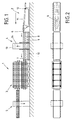
- the invention Veneer ironing system 1 a loading and unloading station 2, one first, in the direction of view Fig.1 right of the multi-daylight press 3 arranged loading and unloading station 4 and one, 1 to the left of the press 3 in the direction of view Fig.1 second removal and loading station 5.
- the loading station 2 is dash-dotted, as in Fig.2 indicated with the veneers to be ironed 6, in here present embodiment manual transfer load, which is 6 in the veneers to be ironed e.g. 12 to 24 sheets can be stacked, e.g. to be arranged in about 5 adjacent rows are.
- veneer sheets 6 to be ironed are then removed from the Loading station 2 in the loading and unloading station 4 spent in such a way that one batch each, indicated in Fig.2 on the top 7 of the four conveyor belts 7,8,9,10 existing loading and unloading station.
- the conveyor belt forming the tray 11 being the Loading station 2, in the present embodiment at his, facing the loading and unloading station Side is height adjustable, i.e. to the Swivel axis 12 is arranged pivotably, it is also it would be conceivable that the tray formed by the conveyor belt 11 is designed to be vertically displaceable overall.
- the Feeding and removal station 4 facing end in such a way proceed that the top of the tray 11 in alignment to the second conveyor belt 8, i.e. to, the second level of Feeding and removal station 4 forming conveyor belt is arranged so that the second batch on the second Conveyor belt 8 of the loading and unloading station 4 can be spent.
- the top 18 of the second conveyor belt 8 of the loading and Removal station 4 is after that previously described vertical movement on one level with the top 19 des, the second upper floor of press 3 down limiting conveyor belt 20th
- the press 3 closed in a conventional manner and the veneers 6.6a in conventionally ironed, i.e. under heat and Exposure to pressure.
- the batches 6,6a are replaced by a Conveying movement in the direction of arrow 34 on the lower belts 9.10 of the loading and unloading station 4, where the loading and unloading station 2 with its tray 11 in one appropriate alignment is brought, i.e. on the one hand Removal of the batch 6 placed on the upper conveyor belt 9, so that the conveyor belt 9 of the loading and Removal station 4 facing end of the tray 11 on a vertical plane is arranged with this, and batch 6 via a normal conveying movement through the conveyor belt 9 the tray 11 is spent.
Landscapes
- Life Sciences & Earth Sciences (AREA)
- Engineering & Computer Science (AREA)
- Mechanical Engineering (AREA)
- Wood Science & Technology (AREA)
- Forests & Forestry (AREA)
- Veneer Processing And Manufacture Of Plywood (AREA)
Applications Claiming Priority (2)
| Application Number | Priority Date | Filing Date | Title |
|---|---|---|---|
| DE19651327A DE19651327A1 (de) | 1996-12-11 | 1996-12-11 | Furnierbügelanlage |
| DE19651327 | 1996-12-11 |
Publications (2)
| Publication Number | Publication Date |
|---|---|
| EP0850734A2 true EP0850734A2 (fr) | 1998-07-01 |
| EP0850734A3 EP0850734A3 (fr) | 2000-10-25 |
Family
ID=7814260
Family Applications (1)
| Application Number | Title | Priority Date | Filing Date |
|---|---|---|---|
| EP97103176A Withdrawn EP0850734A3 (fr) | 1996-12-11 | 1997-02-27 | Presse de placage |
Country Status (4)
| Country | Link |
|---|---|
| EP (1) | EP0850734A3 (fr) |
| CZ (1) | CZ84697A3 (fr) |
| DE (1) | DE19651327A1 (fr) |
| SK (1) | SK35297A3 (fr) |
Cited By (1)
| Publication number | Priority date | Publication date | Assignee | Title |
|---|---|---|---|---|
| CN115816582A (zh) * | 2022-12-19 | 2023-03-21 | 湖南宏森新材料科技有限责任公司 | 一种环保低甲醛生态板热压装置及其生产工艺 |
Family Cites Families (5)
| Publication number | Priority date | Publication date | Assignee | Title |
|---|---|---|---|---|
| FR1473653A (fr) * | 1966-03-31 | 1967-03-17 | Teleflex Italiana S P A | Appareillage automatique d'alimentation de presses, particulièrement de presses pour panneaux ligneux |
| DE2527034C3 (de) * | 1975-06-18 | 1979-09-27 | Maschinenfabrik J. Dieffenbacher Gmbh & Co, 7519 Eppingen | Anlage zur Herstellung von Schichtstoffplatten |
| DE8806883U1 (de) * | 1988-05-26 | 1988-10-20 | WM Wild Maschinen GmbH, 33397 Rietberg | Vorrichtung zum Heißverpressen von plattenförmigen Werkstücken |
| DE3991595T1 (de) * | 1989-02-27 | 1991-02-21 | Raute Oy | Zufuehr- und abfuehrvorrichtung fuer eine presse |
| JP3761258B2 (ja) * | 1996-08-20 | 2006-03-29 | 株式会社名南製作所 | ベニヤ単板圧締処理装置 |
-
1996
- 1996-12-11 DE DE19651327A patent/DE19651327A1/de not_active Withdrawn
-
1997
- 1997-02-27 EP EP97103176A patent/EP0850734A3/fr not_active Withdrawn
- 1997-03-18 SK SK352-97A patent/SK35297A3/sk unknown
- 1997-03-20 CZ CZ97846A patent/CZ84697A3/cs unknown
Cited By (1)
| Publication number | Priority date | Publication date | Assignee | Title |
|---|---|---|---|---|
| CN115816582A (zh) * | 2022-12-19 | 2023-03-21 | 湖南宏森新材料科技有限责任公司 | 一种环保低甲醛生态板热压装置及其生产工艺 |
Also Published As
| Publication number | Publication date |
|---|---|
| DE19651327A1 (de) | 1998-06-18 |
| CZ84697A3 (cs) | 1999-06-16 |
| SK35297A3 (en) | 1999-05-07 |
| EP0850734A3 (fr) | 2000-10-25 |
Similar Documents
| Publication | Publication Date | Title |
|---|---|---|
| DE3019017C2 (fr) | ||
| DE2612206A1 (de) | Heb- und senkbare formlingsbeschickungs- und pressunterlagen-entleerungsvorrichtung fuer eine mehretagenpresse | |
| DE2547149C3 (de) | Stapelvorrichtung zur Beschickung einer Etagenpresse | |
| DE2303353A1 (de) | Verfahren und vorrichtung zum handhaben gleichartiger gegenstaende, z. b. von ziegeln | |
| DE2411660A1 (de) | Vorrichtung zum kuehlen der pressunterlagen im zuge der herstellung von spanplatten, faserplatten u. dgl. | |
| EP0558035B1 (fr) | Dispositif pour empiler des coupelles, notamment des coupelles de vaisselles | |
| DE4224522C1 (de) | Verfahren und Pressenanlage zur Herstellung plattenförmiger, beidseitig mit Furnier versehener Werkstücke | |
| DE2547803B2 (de) | Verfahren und Vorrichtung zum Abführen von Werkstücken aus einer Schneidpresse | |
| EP1338346B1 (fr) | Dispositif de tri à sorties superposées | |
| EP0453806B1 (fr) | Installation pour empiler des pièces constituées d'éléments plats séparés ou de paquets desdits éléments plats | |
| EP0383168B1 (fr) | Presse à plusieurs étages pour des pièces de grande taille | |
| DE10223858A1 (de) | Vorrichtung für die Beschickung und/oder Abstapelung einer Bearbeitungsvorrichtung | |
| EP0850734A2 (fr) | Presse de placage | |
| EP0422600A1 (fr) | Dispositif de transport pour pièces à usiner planes | |
| EP1930119A1 (fr) | Installation mécanique pour le traitement de pièces | |
| CH664710A5 (en) | Sorting wooden planks according to size or quality - using sensors to control endless belts for storing and transporting planks | |
| CH675093A5 (en) | Handling workpieces and machining tools | |
| AT339028B (de) | Heb- und senkbare formlingsbeschickungs- und pressunterlagen-entleerungsvorrichtung fur eine mehretagenpresse | |
| DE2226897C3 (de) | Formungs- und Pressenstraße für die Herstellung von Spanplatten | |
| EP0383169B1 (fr) | Dispositif de transport pour pièces pressées dans une presse transfert pour pièces de grande taille | |
| DE19712319A1 (de) | Durchlaufpresse | |
| DE4314600B4 (de) | Vorrichtung zur lageweisen Stapelung von gruppierten Gegenständen | |
| EP3841045A2 (fr) | Dispositif de palettisation et procédé pour faire fonctionner un dispositif de palettisation | |
| DE3529219A1 (de) | Verfahren zur niveaugleichen stapelung von erzeugnissen ohne eigene steifigkeit auf mehrere stapel | |
| DE4411555C2 (de) | Vorrichtung zum Wechseln von Paletten |
Legal Events
| Date | Code | Title | Description |
|---|---|---|---|
| PUAI | Public reference made under article 153(3) epc to a published international application that has entered the european phase |
Free format text: ORIGINAL CODE: 0009012 |
|
| 17P | Request for examination filed |
Effective date: 19970312 |
|
| AK | Designated contracting states |
Kind code of ref document: A2 Designated state(s): AT BE CH DE DK ES FI FR GB IE IT LI NL PT SE |
|
| AX | Request for extension of the european patent |
Free format text: LT PAYMENT 970312;LV PAYMENT 970312;SI PAYMENT 970312 |
|
| PUAL | Search report despatched |
Free format text: ORIGINAL CODE: 0009013 |
|
| RIC1 | Information provided on ipc code assigned before grant |
Free format text: 7B 27D 3/04 A, 7B 27N 3/22 B, 7B 30B 7/02 B, 7B 27D 3/02 B |
|
| AK | Designated contracting states |
Kind code of ref document: A3 Designated state(s): AT BE CH DE DK ES FI FR GB IE IT LI NL PT SE |
|
| AX | Request for extension of the european patent |
Free format text: LT PAYMENT 19970312;LV PAYMENT 19970312;SI PAYMENT 19970312 |
|
| AKX | Designation fees paid |
Free format text: AT BE CH DE DK ES FI FR GB IE IT LI NL PT SE |
|
| AXX | Extension fees paid |
Free format text: LT PAYMENT 19970312;LV PAYMENT 19970312;SI PAYMENT 19970312 |
|
| STAA | Information on the status of an ep patent application or granted ep patent |
Free format text: STATUS: THE APPLICATION IS DEEMED TO BE WITHDRAWN |
|
| 18D | Application deemed to be withdrawn |
Effective date: 20020903 |