EP0850799A2 - Anzeigeeinheit mit durchleuchtbarem Anzeigeelement - Google Patents
Anzeigeeinheit mit durchleuchtbarem Anzeigeelement Download PDFInfo
- Publication number
- EP0850799A2 EP0850799A2 EP97120607A EP97120607A EP0850799A2 EP 0850799 A2 EP0850799 A2 EP 0850799A2 EP 97120607 A EP97120607 A EP 97120607A EP 97120607 A EP97120607 A EP 97120607A EP 0850799 A2 EP0850799 A2 EP 0850799A2
- Authority
- EP
- European Patent Office
- Prior art keywords
- display unit
- unit according
- diffuser
- light
- display
- Prior art date
- Legal status (The legal status is an assumption and is not a legal conclusion. Google has not performed a legal analysis and makes no representation as to the accuracy of the status listed.)
- Granted
Links
Images

Classifications
-
- G—PHYSICS
- G09—EDUCATION; CRYPTOGRAPHY; DISPLAY; ADVERTISING; SEALS
- G09F—DISPLAYING; ADVERTISING; SIGNS; LABELS OR NAME-PLATES; SEALS
- G09F9/00—Indicating arrangements for variable information in which the information is built-up on a support by selection or combination of individual elements
- G09F9/30—Indicating arrangements for variable information in which the information is built-up on a support by selection or combination of individual elements in which the desired character or characters are formed by combining individual elements
- G09F9/35—Indicating arrangements for variable information in which the information is built-up on a support by selection or combination of individual elements in which the desired character or characters are formed by combining individual elements being liquid crystals
-
- G—PHYSICS
- G02—OPTICS
- G02F—OPTICAL DEVICES OR ARRANGEMENTS FOR THE CONTROL OF LIGHT BY MODIFICATION OF THE OPTICAL PROPERTIES OF THE MEDIA OF THE ELEMENTS INVOLVED THEREIN; NON-LINEAR OPTICS; FREQUENCY-CHANGING OF LIGHT; OPTICAL LOGIC ELEMENTS; OPTICAL ANALOGUE/DIGITAL CONVERTERS
- G02F1/00—Devices or arrangements for the control of the intensity, colour, phase, polarisation or direction of light arriving from an independent light source, e.g. switching, gating or modulating; Non-linear optics
- G02F1/01—Devices or arrangements for the control of the intensity, colour, phase, polarisation or direction of light arriving from an independent light source, e.g. switching, gating or modulating; Non-linear optics for the control of the intensity, phase, polarisation or colour
- G02F1/13—Devices or arrangements for the control of the intensity, colour, phase, polarisation or direction of light arriving from an independent light source, e.g. switching, gating or modulating; Non-linear optics for the control of the intensity, phase, polarisation or colour based on liquid crystals, e.g. single liquid crystal display cells
- G02F1/133—Constructional arrangements; Operation of liquid crystal cells; Circuit arrangements
- G02F1/1333—Constructional arrangements; Manufacturing methods
- G02F1/1335—Structural association of cells with optical devices, e.g. polarisers or reflectors
- G02F1/1336—Illuminating devices
- G02F1/133602—Direct backlight
- G02F1/133606—Direct backlight including a specially adapted diffusing, scattering or light controlling members
-
- G—PHYSICS
- G09—EDUCATION; CRYPTOGRAPHY; DISPLAY; ADVERTISING; SEALS
- G09F—DISPLAYING; ADVERTISING; SIGNS; LABELS OR NAME-PLATES; SEALS
- G09F13/00—Illuminated signs; Luminous advertising
- G09F13/04—Signs, boards or panels, illuminated from behind the insignia
- G09F13/0409—Arrangements for homogeneous illumination of the display surface, e.g. using a layer having a non-uniform transparency
-
- G—PHYSICS
- G02—OPTICS
- G02F—OPTICAL DEVICES OR ARRANGEMENTS FOR THE CONTROL OF LIGHT BY MODIFICATION OF THE OPTICAL PROPERTIES OF THE MEDIA OF THE ELEMENTS INVOLVED THEREIN; NON-LINEAR OPTICS; FREQUENCY-CHANGING OF LIGHT; OPTICAL LOGIC ELEMENTS; OPTICAL ANALOGUE/DIGITAL CONVERTERS
- G02F1/00—Devices or arrangements for the control of the intensity, colour, phase, polarisation or direction of light arriving from an independent light source, e.g. switching, gating or modulating; Non-linear optics
- G02F1/01—Devices or arrangements for the control of the intensity, colour, phase, polarisation or direction of light arriving from an independent light source, e.g. switching, gating or modulating; Non-linear optics for the control of the intensity, phase, polarisation or colour
- G02F1/13—Devices or arrangements for the control of the intensity, colour, phase, polarisation or direction of light arriving from an independent light source, e.g. switching, gating or modulating; Non-linear optics for the control of the intensity, phase, polarisation or colour based on liquid crystals, e.g. single liquid crystal display cells
- G02F1/133—Constructional arrangements; Operation of liquid crystal cells; Circuit arrangements
- G02F1/1333—Constructional arrangements; Manufacturing methods
- G02F1/1335—Structural association of cells with optical devices, e.g. polarisers or reflectors
- G02F1/1336—Illuminating devices
- G02F1/133602—Direct backlight
- G02F1/133606—Direct backlight including a specially adapted diffusing, scattering or light controlling members
- G02F1/133607—Direct backlight including a specially adapted diffusing, scattering or light controlling members the light controlling member including light directing or refracting elements, e.g. prisms or lenses
-
- H—ELECTRICITY
- H01—ELECTRIC ELEMENTS
- H01H—ELECTRIC SWITCHES; RELAYS; SELECTORS; EMERGENCY PROTECTIVE DEVICES
- H01H2219/00—Legends
- H01H2219/054—Optical elements
- H01H2219/056—Diffuser; Uneven surface
-
- H—ELECTRICITY
- H10—SEMICONDUCTOR DEVICES; ELECTRIC SOLID-STATE DEVICES NOT OTHERWISE PROVIDED FOR
- H10W—GENERIC PACKAGES, INTERCONNECTIONS, CONNECTORS OR OTHER CONSTRUCTIONAL DETAILS OF DEVICES COVERED BY CLASS H10
- H10W90/00—Package configurations
Definitions
- the invention relates to a display unit with a transilluminatable display element, on the back of a light source and between light source and a diffuser is arranged.
- a display unit with a liquid crystal cell, with one on the side of the liquid crystal cell facing away from an observer Light box and a light source arranged in it transmissive lighting of the liquid crystal cell known.
- a transparent, light-scattering Spreading disc arranged between the Light source and the liquid crystal cell. The spreading disc causes an equalization of the light emitted by the light source and thus an illumination the liquid crystal cell without major jumps in brightness in the display plane.
- a display unit with a radiolucent display element of said Art so designed that high brightness in a display area is guaranteed without using a more powerful light source becomes.
- the assembly of the display unit should be simple and the variety of components can be kept low.
- the object is achieved in that between the Light source and the display element an approximately disc-shaped, clear Element is arranged, the one facing the display element Surface is rasterized approximately pyramid-shaped and on the display element opposite side of the diffuser is arranged.
- the display element is a viewing window, e.g. Part of a combination instrument Krafflahrzeugs can be.
- the lens is preferably colored and In a further advantageous embodiment, symbols and / or Have characters. This is the one of an activated display element further increase outgoing information content.
- the display element is particularly advantageously a liquid crystal cell. Especially in the case of liquid crystal cells, information is very useful needs a lot of light. An increase in the number of light sources or the However, using stronger light sources requires a lot of space, an impermissibly high heat generation and higher costs.
- the diffuser is a roughened one Surface of the clear element. In this way there is Display unit made up of very few elements. But it can also be advantageous if the diffuser is made of a transparent material, in which scattered pigments or scattering particles are arranged. The light-scattering properties of the diffuser can be further improved in this way will. If the diffuser is disc-shaped, it can be particularly simple manufactured and installed in the display unit.
- a further simplifying embodiment of the display unit is the diffuser forming a single component connected to the clear element. Especially it makes sense to use this component as a 2-component molded part to execute.
- Such a molded part is in a particularly few process steps producible and has inside, i.e. between diffuser and clear element, no transition surface. The absence Such a light transition surface is particularly favorable because this minimizes the loss of light. Step on a transition surface usually light losses of at least 4%.
- the diffuser and the clear element are not a single component connected forming, it may be advantageous if between the diffuser and an air gap is arranged in the clear element. To this Wise becomes an accumulation of water vapor leading to staining avoided between the two components.
- the light source is advantageously an LED or an incandescent lamp, which makes a particularly simple construction of the display unit and an inexpensive Manufacturing can be achieved. Since the display unit according to the invention but also significant advantages when illuminating larger display elements, e.g. LCD color screens, offers, it is also cheap, when the light source is a fluorescent lamp. Becomes a colored fluoroscopy of the display element, the light source can be advantageous emit colored light. The same effect can be achieved if the diffuser is colored.
- the approximately pyramid-shaped grid of the surface preferably has of the clear element pyramids with square or rectangular Footprint on. Since the surface is a light-active element, special importance is attached to their optical quality. A grid with square or rectangular pyramids is particularly easy to manufacture and already ensures a significant one Light collection. It is necessary to make the pyramid structure as fine to design that this is not visible on the display element in order to get no optically disturbing effect.
- the pyramid-shaped surface structure can be matched to the geometric Shape of the display element and that in the intended application typically occurring viewing angle. Accordingly, the structure can be chosen so that the display element under the aforementioned Viewing angle is particularly brightly lit.
- the roughly pyramid-shaped grid of the surface of the light-clear element therefore preferably has pyramids with a triangular or polygonal base on.
- the light-clear element preferably has a coding.
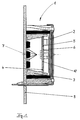
- a display unit 1 shown in FIG. 1 is replaced by a printed circuit board 9 held.
- On the circuit board 9 are light sources 7 and one as a housing component trained light box 3 arranged.
- the display element 2 can be illuminated by the light sources 7.
- a light-clear element 5 Between the display element 2 and light sources 7 is a light-clear element 5 arranged with a rastered surface 6 and a diffuser 4. Between Diffuser 4 and clear element 5 there is an air gap 10, the formation of water spots due to condensation counteracts.
- the clear element 5 is with its screened Surface 6 of the display element 2 and the diffuser 4 of the light sources 7 facing.
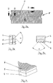
- FIG. 2 The effect of a pyramid structure of the rasterized surface 6 of the light-clear element 5 is illustrated in FIG. 2.
- a light beam 11, the perpendicular to the diffuser disc 4 is due to the pyramid structure (with an angle ⁇ of 90 °) deflected by 180 ° and reflected back. If it strikes a scattering pigment 12 after re-entry into the diffuser 4, see it is sprinkled and can be returned to the Meet the pyramid structure of the surface 6 (light beam 13).
- the Light beam 13 broken away from Lot 14 according to the law of refraction. However, this means that it is broken towards the display element normal 15 becomes.
- the angle ⁇ at which a light beam strikes the surface 6, is greater than 45 ° minus the critical angle of the total reflection, so the Light beam on the surface (pyramid structure) is broken, otherwise it will he reflects. Is a light beam 16 of the light source 7 on a pigment in the diffuser disc 4 is scattered and thus hits at a larger angle seen from the display element normal 15 to the pyramid structure, so it is broken again towards the display element normal 15.
- the aforementioned effects lead to a greater luminance in Direction of the display element normals and to a more uniform Illumination of the display element.
- the display element is preferred from a different one than that corresponding to the display element normals Viewed in the direction, the surface structure of the light-clear element to be chosen so that in this other direction a larger one Luminance is present.
- FIG. 3a shows a front view of a pyramid structure screened surface 6 of a light-clear element 5.
- a coding 8 represents the correct installation position when installing the clear element 5 in the display unit.
- 3b and 3c the cuts along lines A-A and B-B of the component of Fig. 3a can be seen, the light-clear element 5 is a single component with connected to the diffuser 4. This component is e.g. a 2-component molded part made of plastic.
- the angle ⁇ between the pyramids on the rastered surface 6 here is approximately 90 °.
- the 2-component molded part from Fig. 3a is - the pyramid structure of the Clarifying surface 6 of the light-clear element 5 - in perspective in FIG. 4 shown.
Landscapes
- Physics & Mathematics (AREA)
- General Physics & Mathematics (AREA)
- Engineering & Computer Science (AREA)
- Theoretical Computer Science (AREA)
- Chemical & Material Sciences (AREA)
- Crystallography & Structural Chemistry (AREA)
- Nonlinear Science (AREA)
- Optics & Photonics (AREA)
- Mathematical Physics (AREA)
- Devices For Indicating Variable Information By Combining Individual Elements (AREA)
- Details Of Measuring Devices (AREA)
- Illuminated Signs And Luminous Advertising (AREA)
- Liquid Crystal (AREA)
Abstract
Description
- Fig. 1
- eine erfindungsgemäße Anzeigeeinheit in geschnittener Darstellung,
- Fig. 2
- einen Ausschnitt einer erfindungsgemäßen Anzeigeeinheit in einer zweiten Ausführungsform in geschnittener Darstellung,
- Fig. 3
- einen Diffusor und ein lichtklares Element, ein einziges Bauteil bildend, in verschiedenen Ansichten und
- Fig. 4
- das Bauteil aus Fig. 3 in ausschnittsweiser und perspektivischer Darstellung.
Claims (20)
- Anzeigeeinheit mit einem durchleuchtbaren Anzeigeelement, auf dessen Rückseite eine Lichtquelle und zwischen Lichtquelle und Anzeigeelement ein Diffusor angeordnet ist, dadurch gekennzeichnet, daß zwischen der Lichtquelle (7) und dem Anzeigeelement (2) ein in etwa scheibenförmiges, lichtklares Element (5) angeordnet ist, dessen dem Anzeigeelement (2) zugewandte Oberfläche (6) in etwa pyramidenförmig gerastert ist und an dessen dem Anzeigeelement (2) abgewandten Seite der Diffusor (4) angeordnet ist.
- Anzeigeeinheit nach Anspruch 1, dadurch gekennzeichnet, daß das Anzeigeelement (2) eine Sichtscheibe ist.
- Anzeigeeinheit nach Anspruch 2, dadurch gekennzeichnet, daß die Sichtscheibe farbig ist.
- Anzeigeeinheit nach einem der Ansprüche 2 oder 3, dadurch gekennzeichnet, daß die Sichtscheibe Symbole und/oder Schriftzeichen aufweist.
- Anzeigeeinheit nach Anspruch 1, dadurch gekennzeichnet, daß das Anzeigeelement (2) eine Flüssigkristallzelle ist.
- Anzeigeeinheit nach einem der vorhergehenden Ansprüche, dadurch gekennzeichnet, daß der Diffusor (4) eine aufgerauhte Oberfläche des lichtklaren Elements (6) ist.
- Anzeigeeinheit nach einem der Ansprüche 1 bis 5, dadurch gekennzeichnet, daß der Diffusor (4) aus einem transparenten Werkstoff besteht, in dem verteilt Streupigmente oder Streuteilchen angeordnet sind.
- Anzeigeeinheit nach einem der vorhergehenden Ansprüche, dadurch gekennzeichnet, daß der Diffusor (4) scheibenförmig ist.
- Anzeigeeinheit nach einem der vorhergehenden Ansprüche, dadurch gekennzeichnet, daß der Diffusor (4) ein einziges Bauteil bildend mit dem lichtklaren Element (5) verbunden ist.
- Anzeigeeinheit nach einem der Ansprüche 1 bis 5 oder 7 bis 8, dadurch gekennzeichnet, daß zwischen dem Diffusor (4) und dem lichtklaren Element (5) ein Luftspalt angeordnet ist.
- Anzeigeeinheit nach einem der vorhergehenden Ansprüche, dadurch gekennzeichnet, daß der Diffusor (4) farbig ist.
- Anzeigeeinheit nach einem der vorhergehenden Ansprüche, dadurch gekennzeichnet, daß die Lichtquelle (7) eine LED oder eine Glühlampe ist.
- Anzeigeeinheit nach einem der Ansprüche 1 bis 11, dadurch gekennzeichnet, daß die Lichtquelle (7) eine Leuchtstofflampe ist.
- Anzeigeeinheit nach einem der vorhergehenden Ansprüche, dadurch gekennzeichnet, daß die Lichtquelle (7) farbiges Licht ausstrahlt.
- Anzeigeeinheit nach einem der vorhergehenden Ansprüche, dadurch gekennzeichnet, daß die in etwa pyramidenförmige Rasterung der Oberfläche (6) des lichtklaren Elements (5) Pyramiden mit quadratischer oder rechteckiger Grundfläche aufweist.
- Anzeigeeinheit nach einem der vorhergehenden Ansprüche, dadurch gekennzeichnet, daß die in etwa pyramidenförmige Rasterung der Oberfläche (6) des lichtklaren Elements (5) Pyramiden mit drei- oder mehreckiger Grundfläche aufweist.
- Anzeigeeinheit nach einem der vorhergehenden Ansprüche, dadurch gekennzeichnet, daß die in etwa pyramidenförmige Rasterung der Oberfläche (6) des lichtklaren Elements (5) Pyramidenstümpfe aufweist.
- Anzeigeeinheit nach einem der vorhergehenden Ansprüche, dadurch gekennzeichnet, daß die in etwa pyramidenförmige Rasterung der Oberfläche (6) des lichtklaren Elements (5) Pyramiden und/oder Pyramidenstümpfe mit einheitlicher Grundfläche und Höhe aufweist.
- Anzeigeeinheit nach einem der Ansprüche 1 bis 17, dadurch gekennzeichnet, daß die in etwa pyramidenförmige Rasterung der Oberfläche (6) des lichtklaren Elements (5) Pyramiden und/oder Pyramidenstümpfe mit unterschiedlicher Grundfläche und/oder Höhe aufweist.
- Anzeigeeinheit nach einem der vorhergehenden Ansprüche, dadurch gekennzeichnet, daß das lichtklare Element (5) eine Codierung (8) aufweist.
Applications Claiming Priority (2)
| Application Number | Priority Date | Filing Date | Title |
|---|---|---|---|
| DE19654418A DE19654418A1 (de) | 1996-12-24 | 1996-12-24 | Anzeigeeinheit |
| DE19654418 | 1996-12-24 |
Publications (3)
| Publication Number | Publication Date |
|---|---|
| EP0850799A2 true EP0850799A2 (de) | 1998-07-01 |
| EP0850799A3 EP0850799A3 (de) | 1999-06-09 |
| EP0850799B1 EP0850799B1 (de) | 2002-08-14 |
Family
ID=7816252
Family Applications (1)
| Application Number | Title | Priority Date | Filing Date |
|---|---|---|---|
| EP97120607A Expired - Lifetime EP0850799B1 (de) | 1996-12-24 | 1997-11-25 | Anzeigeeinheit mit durchleuchtbarem Anzeigeelement |
Country Status (2)
| Country | Link |
|---|---|
| EP (1) | EP0850799B1 (de) |
| DE (2) | DE19654418A1 (de) |
Cited By (2)
| Publication number | Priority date | Publication date | Assignee | Title |
|---|---|---|---|---|
| WO2000021061A3 (de) * | 1998-10-01 | 2000-11-16 | Wustlich Daniel | Mit weisslicht arbeitende hintergrundbeleuchtung |
| FR2862140A1 (fr) * | 2003-11-07 | 2005-05-13 | Thales Sa | Boite a lumiere a diodes electromuminescentes pour visualisations |
Families Citing this family (13)
| Publication number | Priority date | Publication date | Assignee | Title |
|---|---|---|---|---|
| DE19831004A1 (de) * | 1998-07-10 | 2000-02-03 | Volkswagen Ag | LED-Leuchte für ein Kraftfahrzeug |
| DE19834538B4 (de) * | 1998-07-31 | 2010-04-08 | Abb Ag | Elektronisches Installationsgerät der Gebäudeinstallationstechnik mit hintergrundbeleuchteter LCD-Anzeige |
| DE10201029A1 (de) * | 2002-01-11 | 2003-07-24 | Siemens Ag | Anzeigevorrichtung |
| DE10245580B4 (de) * | 2002-09-27 | 2006-06-01 | Siemens Ag | Einrichtung zur Erzeugung eines Bildes |
| DE10250675A1 (de) * | 2002-10-31 | 2004-05-19 | Hella Kg Hueck & Co. | Anzeigeneinheit, isbesondere für Kraftfahrzeuge |
| DE10260831B3 (de) | 2002-12-23 | 2004-04-15 | Lisa Dräxlmaier GmbH | Beleuchtungssystem für Anzeigen in Fahrzeugen |
| US7441913B2 (en) | 2002-12-23 | 2008-10-28 | Lisa Dräxlmaier GmbH | Lighting system for displays in vehicles |
| DE102004009208A1 (de) * | 2004-02-25 | 2005-09-22 | Lisa Dräxlmaier GmbH | Beleuchtungssystem für Anzeigen in Fahrzeugen |
| DE102005018282A1 (de) * | 2005-04-13 | 2006-10-19 | Würth Elektronik GmbH & Co. KG | Leiterplattenbeleuchtung |
| FR2913135B1 (fr) * | 2007-02-23 | 2010-06-11 | Visteon Global Tech Inc | Element d'habillage pourvu d'un dispositif d'affichage et procede de fabrication d'un tel element |
| DE102007057671A1 (de) * | 2007-11-30 | 2009-06-04 | Osram Opto Semiconductors Gmbh | Beleuchtungsvorrichtung |
| DE102013217709A1 (de) * | 2013-09-05 | 2015-03-05 | Carl Zeiss Microscopy Gmbh | Beleuchtungsvorrichtung und digitaler Profilprojektor |
| DE102013223244A1 (de) * | 2013-11-14 | 2015-05-21 | Zf Friedrichshafen Ag | Vorrichtung zur Anzeige zumindest eines Symbols und Verfahren zum Herstellen einer Vorrichtung zur Anzeige zumindest eines Symbols |
Family Cites Families (5)
| Publication number | Priority date | Publication date | Assignee | Title |
|---|---|---|---|---|
| DE3921304A1 (de) * | 1989-06-29 | 1991-01-10 | Hella Kg Hueck & Co | Anzeigeeinrichtung |
| JP3006306B2 (ja) * | 1992-09-16 | 2000-02-07 | インターナショナル・ビジネス・マシーンズ・コーポレイション | 光学的フイルム及び上記光学的フイルムを用いた液晶表示装置 |
| DE69409977T2 (de) * | 1993-01-11 | 1998-10-22 | Koninkl Philips Electronics Nv | Beleuchtungssystem und ein solches System umfassendes Anzeigegerät |
| JPH06308485A (ja) * | 1993-04-21 | 1994-11-04 | Hitachi Ltd | 表示装置 |
| JPH08129175A (ja) * | 1994-11-01 | 1996-05-21 | Sekisui Chem Co Ltd | 光制御シート及びこれを備えた面状発光装置 |
-
1996
- 1996-12-24 DE DE19654418A patent/DE19654418A1/de not_active Ceased
-
1997
- 1997-11-25 DE DE59707963T patent/DE59707963D1/de not_active Expired - Fee Related
- 1997-11-25 EP EP97120607A patent/EP0850799B1/de not_active Expired - Lifetime
Non-Patent Citations (1)
| Title |
|---|
| None |
Cited By (3)
| Publication number | Priority date | Publication date | Assignee | Title |
|---|---|---|---|---|
| WO2000021061A3 (de) * | 1998-10-01 | 2000-11-16 | Wustlich Daniel | Mit weisslicht arbeitende hintergrundbeleuchtung |
| FR2862140A1 (fr) * | 2003-11-07 | 2005-05-13 | Thales Sa | Boite a lumiere a diodes electromuminescentes pour visualisations |
| WO2005045943A1 (fr) * | 2003-11-07 | 2005-05-19 | Thales | Boite a lumiere a diodes electroluminescentes pour visualisations |
Also Published As
| Publication number | Publication date |
|---|---|
| DE19654418A1 (de) | 1998-06-25 |
| EP0850799B1 (de) | 2002-08-14 |
| DE59707963D1 (de) | 2002-09-19 |
| EP0850799A3 (de) | 1999-06-09 |
Similar Documents
| Publication | Publication Date | Title |
|---|---|---|
| EP0850799B1 (de) | Anzeigeeinheit mit durchleuchtbarem Anzeigeelement | |
| EP1231430B1 (de) | Beleuchtungseinrichtung mit punktförmigen Lichtquellen | |
| DE4129094B4 (de) | Signalleuchte mit Leuchtdioden als Lichtquelle für Kraftfahrzeuge und deren Verwendung für unterschiedliche Signalleuchtenfunktionen | |
| EP0930600A1 (de) | Optikelement aus LED und zwei Linsen für die Erzeugung eines Lichtpunktes für Verkehrszeichen und Anzeigetafeln | |
| DE19521254A1 (de) | Anzeigesystem mit Helligkeitsverstärkungsfilm | |
| EP1077344A2 (de) | Leuchte | |
| DE3912646C2 (de) | Nummernschildanordnung mit beleuchtbaren Kennzeichenelementen | |
| DE3123369A1 (de) | Lichtleiter | |
| DE10214566B4 (de) | Homogen paralleles Licht emittierende Leuchtdiode | |
| DE102009025399A1 (de) | Leuchtkörper mit Reflektoren zur gleichmäßigen Flächenausleuchtung | |
| DE4105547A1 (de) | Flache, beleuchtete warn- oder anzeigeeinrichtung | |
| DE20004188U1 (de) | Leuchte | |
| DE10333907A1 (de) | LED-Strahler | |
| CH688251A5 (de) | Anzeige-Vorrichtung und -Feld. | |
| DE9105201U1 (de) | Anordnung zur Ausleuchtung von Hintergrundsflächen | |
| DE102021116840A1 (de) | Lichtmodul, insbesondere für eine Beleuchtungseinrichtung eines Fahrzeuges, und Beleuchtungseinrichtung eines Fahrzeuges | |
| DE9000867U1 (de) | Leuchtbox | |
| EP1335218A1 (de) | Lichtleiteranordnung und Beleuchtungseinrichtung mit einer solchen Anordnung | |
| DE3033462A1 (de) | Beleuchtungsvorrichtung zur hinterleuchtung eines transparentes mit hoher gleichmaessigkeit | |
| DE10306870A1 (de) | Leuchtanzeigeeinrichtung | |
| DE102014104339B4 (de) | Zentrales Aufhellungselement für LED-Leuchten | |
| DE202019106804U1 (de) | Optisches System zum Beeinflussen der Lichtabgabe einer länglichen Lichtquelle | |
| EP4168711B1 (de) | Anordnung zur lichtabgabe und leuchte | |
| DE3129038A1 (de) | Hinweisleuchte | |
| DE102017129505A1 (de) | LED-Band |
Legal Events
| Date | Code | Title | Description |
|---|---|---|---|
| PUAI | Public reference made under article 153(3) epc to a published international application that has entered the european phase |
Free format text: ORIGINAL CODE: 0009012 |
|
| AK | Designated contracting states |
Kind code of ref document: A2 Designated state(s): DE FR GB |
|
| AX | Request for extension of the european patent |
Free format text: AL;LT;LV;MK;RO;SI |
|
| PUAL | Search report despatched |
Free format text: ORIGINAL CODE: 0009013 |
|
| AK | Designated contracting states |
Kind code of ref document: A3 Designated state(s): AT BE CH DE DK ES FI FR GB GR IE IT LI LU MC NL PT SE |
|
| AX | Request for extension of the european patent |
Free format text: AL;LT;LV;MK;RO;SI |
|
| 17P | Request for examination filed |
Effective date: 19990709 |
|
| AKX | Designation fees paid |
Free format text: DE FR GB |
|
| 17Q | First examination report despatched |
Effective date: 20010417 |
|
| RAP1 | Party data changed (applicant data changed or rights of an application transferred) |
Owner name: SIEMENS AKTIENGESELLSCHAFT |
|
| GRAG | Despatch of communication of intention to grant |
Free format text: ORIGINAL CODE: EPIDOS AGRA |
|
| GRAG | Despatch of communication of intention to grant |
Free format text: ORIGINAL CODE: EPIDOS AGRA |
|
| GRAH | Despatch of communication of intention to grant a patent |
Free format text: ORIGINAL CODE: EPIDOS IGRA |
|
| GRAH | Despatch of communication of intention to grant a patent |
Free format text: ORIGINAL CODE: EPIDOS IGRA |
|
| GRAA | (expected) grant |
Free format text: ORIGINAL CODE: 0009210 |
|
| AK | Designated contracting states |
Kind code of ref document: B1 Designated state(s): DE FR GB |
|
| REG | Reference to a national code |
Ref country code: GB Ref legal event code: FG4D Free format text: NOT ENGLISH |
|
| REF | Corresponds to: |
Ref document number: 59707963 Country of ref document: DE Date of ref document: 20020919 |
|
| GBT | Gb: translation of ep patent filed (gb section 77(6)(a)/1977) |
Effective date: 20021028 |
|
| ET | Fr: translation filed | ||
| PLBE | No opposition filed within time limit |
Free format text: ORIGINAL CODE: 0009261 |
|
| STAA | Information on the status of an ep patent application or granted ep patent |
Free format text: STATUS: NO OPPOSITION FILED WITHIN TIME LIMIT |
|
| 26N | No opposition filed |
Effective date: 20030515 |
|
| PGFP | Annual fee paid to national office [announced via postgrant information from national office to epo] |
Ref country code: DE Payment date: 20081121 Year of fee payment: 12 |
|
| PGFP | Annual fee paid to national office [announced via postgrant information from national office to epo] |
Ref country code: FR Payment date: 20081113 Year of fee payment: 12 |
|
| PGFP | Annual fee paid to national office [announced via postgrant information from national office to epo] |
Ref country code: GB Payment date: 20081117 Year of fee payment: 12 |
|
| GBPC | Gb: european patent ceased through non-payment of renewal fee |
Effective date: 20091125 |
|
| REG | Reference to a national code |
Ref country code: FR Ref legal event code: ST Effective date: 20100730 |
|
| PG25 | Lapsed in a contracting state [announced via postgrant information from national office to epo] |
Ref country code: FR Free format text: LAPSE BECAUSE OF NON-PAYMENT OF DUE FEES Effective date: 20091130 |
|
| PG25 | Lapsed in a contracting state [announced via postgrant information from national office to epo] |
Ref country code: DE Free format text: LAPSE BECAUSE OF NON-PAYMENT OF DUE FEES Effective date: 20100601 |
|
| PG25 | Lapsed in a contracting state [announced via postgrant information from national office to epo] |
Ref country code: GB Free format text: LAPSE BECAUSE OF NON-PAYMENT OF DUE FEES Effective date: 20091125 |