EP0850813A2 - Bremsanlage - Google Patents
Bremsanlage Download PDFInfo
- Publication number
- EP0850813A2 EP0850813A2 EP97122828A EP97122828A EP0850813A2 EP 0850813 A2 EP0850813 A2 EP 0850813A2 EP 97122828 A EP97122828 A EP 97122828A EP 97122828 A EP97122828 A EP 97122828A EP 0850813 A2 EP0850813 A2 EP 0850813A2
- Authority
- EP
- European Patent Office
- Prior art keywords
- brake fluid
- pressure
- wheel
- brake
- conduit
- Prior art date
- Legal status (The legal status is an assumption and is not a legal conclusion. Google has not performed a legal analysis and makes no representation as to the accuracy of the status listed.)
- Granted
Links
- 239000012530 fluid Substances 0.000 claims abstract description 374
- 230000002265 prevention Effects 0.000 claims description 93
- 230000001105 regulatory effect Effects 0.000 claims description 21
- 230000001276 controlling effect Effects 0.000 claims description 13
- 230000000694 effects Effects 0.000 claims description 9
- 230000004044 response Effects 0.000 claims description 6
- 230000001747 exhibiting effect Effects 0.000 claims 2
- 238000012545 processing Methods 0.000 description 136
- 230000007423 decrease Effects 0.000 description 39
- 230000003247 decreasing effect Effects 0.000 description 27
- 238000010276 construction Methods 0.000 description 19
- 238000000034 method Methods 0.000 description 9
- 230000001133 acceleration Effects 0.000 description 8
- 238000010586 diagram Methods 0.000 description 8
- 230000004043 responsiveness Effects 0.000 description 7
- 238000013459 approach Methods 0.000 description 6
- 230000033228 biological regulation Effects 0.000 description 6
- 230000008569 process Effects 0.000 description 6
- 238000001514 detection method Methods 0.000 description 5
- 230000009467 reduction Effects 0.000 description 3
- 230000008859 change Effects 0.000 description 2
- 230000010349 pulsation Effects 0.000 description 2
- 230000000630 rising effect Effects 0.000 description 2
- 238000004904 shortening Methods 0.000 description 2
- 230000009471 action Effects 0.000 description 1
- 230000008901 benefit Effects 0.000 description 1
- XULSCZPZVQIMFM-IPZQJPLYSA-N odevixibat Chemical compound C12=CC(SC)=C(OCC(=O)N[C@@H](C(=O)N[C@@H](CC)C(O)=O)C=3C=CC(O)=CC=3)C=C2S(=O)(=O)NC(CCCC)(CCCC)CN1C1=CC=CC=C1 XULSCZPZVQIMFM-IPZQJPLYSA-N 0.000 description 1
- 230000035939 shock Effects 0.000 description 1
- 238000004088 simulation Methods 0.000 description 1
Images





Classifications
-
- B—PERFORMING OPERATIONS; TRANSPORTING
- B60—VEHICLES IN GENERAL
- B60T—VEHICLE BRAKE CONTROL SYSTEMS OR PARTS THEREOF; BRAKE CONTROL SYSTEMS OR PARTS THEREOF, IN GENERAL; ARRANGEMENT OF BRAKING ELEMENTS ON VEHICLES IN GENERAL; PORTABLE DEVICES FOR PREVENTING UNWANTED MOVEMENT OF VEHICLES; VEHICLE MODIFICATIONS TO FACILITATE COOLING OF BRAKES
- B60T8/00—Arrangements for adjusting wheel-braking force to meet varying vehicular or ground-surface conditions, e.g. limiting or varying distribution of braking force
- B60T8/32—Arrangements for adjusting wheel-braking force to meet varying vehicular or ground-surface conditions, e.g. limiting or varying distribution of braking force responsive to a speed condition, e.g. acceleration or deceleration
- B60T8/34—Arrangements for adjusting wheel-braking force to meet varying vehicular or ground-surface conditions, e.g. limiting or varying distribution of braking force responsive to a speed condition, e.g. acceleration or deceleration having a fluid pressure regulator responsive to a speed condition
- B60T8/48—Arrangements for adjusting wheel-braking force to meet varying vehicular or ground-surface conditions, e.g. limiting or varying distribution of braking force responsive to a speed condition, e.g. acceleration or deceleration having a fluid pressure regulator responsive to a speed condition connecting the brake actuator to an alternative or additional source of fluid pressure, e.g. traction control systems
- B60T8/4809—Traction control, stability control, using both the wheel brakes and other automatic braking systems
- B60T8/4827—Traction control, stability control, using both the wheel brakes and other automatic braking systems in hydraulic brake systems
- B60T8/4863—Traction control, stability control, using both the wheel brakes and other automatic braking systems in hydraulic brake systems closed systems
- B60T8/4872—Traction control, stability control, using both the wheel brakes and other automatic braking systems in hydraulic brake systems closed systems pump-back systems
-
- B—PERFORMING OPERATIONS; TRANSPORTING
- B60—VEHICLES IN GENERAL
- B60T—VEHICLE BRAKE CONTROL SYSTEMS OR PARTS THEREOF; BRAKE CONTROL SYSTEMS OR PARTS THEREOF, IN GENERAL; ARRANGEMENT OF BRAKING ELEMENTS ON VEHICLES IN GENERAL; PORTABLE DEVICES FOR PREVENTING UNWANTED MOVEMENT OF VEHICLES; VEHICLE MODIFICATIONS TO FACILITATE COOLING OF BRAKES
- B60T8/00—Arrangements for adjusting wheel-braking force to meet varying vehicular or ground-surface conditions, e.g. limiting or varying distribution of braking force
- B60T8/32—Arrangements for adjusting wheel-braking force to meet varying vehicular or ground-surface conditions, e.g. limiting or varying distribution of braking force responsive to a speed condition, e.g. acceleration or deceleration
- B60T8/34—Arrangements for adjusting wheel-braking force to meet varying vehicular or ground-surface conditions, e.g. limiting or varying distribution of braking force responsive to a speed condition, e.g. acceleration or deceleration having a fluid pressure regulator responsive to a speed condition
- B60T8/38—Arrangements for adjusting wheel-braking force to meet varying vehicular or ground-surface conditions, e.g. limiting or varying distribution of braking force responsive to a speed condition, e.g. acceleration or deceleration having a fluid pressure regulator responsive to a speed condition including valve means of the relay or driver controlled type
-
- B—PERFORMING OPERATIONS; TRANSPORTING
- B60—VEHICLES IN GENERAL
- B60T—VEHICLE BRAKE CONTROL SYSTEMS OR PARTS THEREOF; BRAKE CONTROL SYSTEMS OR PARTS THEREOF, IN GENERAL; ARRANGEMENT OF BRAKING ELEMENTS ON VEHICLES IN GENERAL; PORTABLE DEVICES FOR PREVENTING UNWANTED MOVEMENT OF VEHICLES; VEHICLE MODIFICATIONS TO FACILITATE COOLING OF BRAKES
- B60T8/00—Arrangements for adjusting wheel-braking force to meet varying vehicular or ground-surface conditions, e.g. limiting or varying distribution of braking force
- B60T8/32—Arrangements for adjusting wheel-braking force to meet varying vehicular or ground-surface conditions, e.g. limiting or varying distribution of braking force responsive to a speed condition, e.g. acceleration or deceleration
- B60T8/34—Arrangements for adjusting wheel-braking force to meet varying vehicular or ground-surface conditions, e.g. limiting or varying distribution of braking force responsive to a speed condition, e.g. acceleration or deceleration having a fluid pressure regulator responsive to a speed condition
- B60T8/40—Arrangements for adjusting wheel-braking force to meet varying vehicular or ground-surface conditions, e.g. limiting or varying distribution of braking force responsive to a speed condition, e.g. acceleration or deceleration having a fluid pressure regulator responsive to a speed condition comprising an additional fluid circuit including fluid pressurising means for modifying the pressure of the braking fluid, e.g. including wheel driven pumps for detecting a speed condition, or pumps which are controlled by means independent of the braking system
- B60T8/404—Control of the pump unit
- B60T8/4054—Control of the pump unit involving the delivery pressure control
Definitions
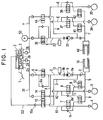
- a conduit (equivalent to the second conduit D2 in the front wheel piping system) connecting the conduit G between an ABS control use reservoir 40 and the rear wheel pump 39 to the master reservoir 3 is not provided. This is to reduce the cost of this conduit part and to increase failsafe ability.
- failsafe for example, in the front wheel piping system, because the conduit D2 connected to the master reservoir 3 is provided, there is a possibility of the front wheel second control valve 15 and the nonreturn valve 15a open-failing.
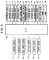
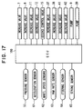
- Solenoid drive patterns are shown in Fig. 5, Fig. 8 and Fig. 10B. Regarding the ON and the OFF in these figures, when there is no movement from the valve position in normal braking (showing the state of Fig. 1) it is shown with OFF and conversely when the valve position is moved it is shown with ON.
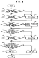
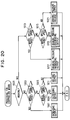
- step 301 At the time of the oversteering state shown in Fig. 7, because the wheel being sideslip prevention controlled is the right front wheel 51, processing of step 301 is executed with respect to the right front wheel 51.
- step 301 a target wheel speed set as a wheel speed corresponding to the current state of the slip angle and the actual wheel speed at the right front wheel 51 are compared. That is, it is determined whether or not the speed of the right front wheel 51 being controlled has exceeded the target wheel speed. If the actual wheel speed has exceeded the target wheel speed processing proceeds to step 303 and sets a pulse increasing output to reduce the actual wheel speed.
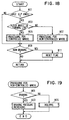
- step 501 it is determined whether or not either of the front wheels is in sideslip prevention control. In this description, because it is being assumed that sideslip prevention control is being carried out for the right front wheel 51, that determination is YES and processing proceeds to step 502.
- step 502 it is determined whether or not the vehicle is currently being braked. This determination of whether or not the vehicle is currently being braked is determined by detecting based on the signal of a stroke sensor 65 whether or not the brake pedal 1 is in a moving state. In this case, because it is a time of non-braking, the solenoid drive pattern (A) shown in Fig. 10B is selected.
- This processing in a time of braking includes both cases wherein there was a stepping on the brake pedal after a state of oversteering occurred during non-braking and there was a state of oversteering occurred after the brake pedal was stepped on.
- step 304 it is determined which command of increase, holding, decrease of the W/C pressure with respect to each of the non-controlled wheels should be outputted.
- the detailed processing of step 304 is shown in Fig. 9.
- brake fluid is increased to substantially the same pressure as the M/C pressure (if pressure decreasing control has not been executed) and to the right front wheel that is the wheel to be controlled a pressure adjusted by sideslip prevention control is applied.
- the master cylinder 2 can produce approximately the same brake fluid pressure not only in the front wheel side but also in the rear wheel side during non-braking when the brake fluid pressure of the front wheel side is transmitted to the rear wheel side through the master cylinder 2. That is, the same pressure arises in the primary chamber and the secondary chamber as the result that brake fluid is fed to the primary chamber 2A of the master cylinder 2.
- the conduit A branches into two conduits A1, A2, and the conduit A1 transmits brake fluid to the wheel cylinder 5, and the conduit A2 transmits brake fluid to the wheel cylinder 34.
- a first pressure increase control valve 7 for controlling pressure increase to the wheel cylinder 5 is provided in the conduit A1 .
- a second pressure increase control valve 8 for controlling pressure increase to the wheel cylinder 34 is provided.
- These first and second pressure increase control valves 7, 8 are two-position valves which can be controlled between open and closed states. When these first and second pressure increase control valves 7, 8 are controlled to their open states, an M/C pressure or a brake fluid pressure produced by delivery of brake fluid of a first pump 9 which will be further discussed later can be applied to the wheel cylinders 5, 34.
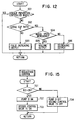
- step 809 determination of whether or not braking is in progress is carried out. Whether or not braking is in progress is determined on the basis of the M/C pressure detected by the pressure sensor 50. That is, when a pressure increasing output command which will be further discussed later has not been issued with respect to the controlled wheel, unless the driver steps on the brake pedal 1 the M/C pressure does not increase. Therefore, when a pressure increasing output command has not been issued and when the M/C pressure increases, a braking determination flag is set and it is deemed that braking is in progress.
- step 1015 When in step 1015 the determination is No, a braking holding output command is issued at step 1021 and processing is ended.
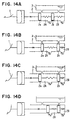
- this braking holding output command is set, the ECU 100 drives solenoids of the control valves corresponding to the controlled wheel and moves the valve members of the control valves to the valve positions of the solenoid drive pattern (F) shown in Fig. 21. That is, when the braking holding output command is set, the third pressure increase control valve 37 corresponding to the right front wheel 51 is brought to the on-state (closed state) and the third pressure decrease control valve 41 to its off-state (closed state), and the first control valve 25 is brought to its off-state (open state) and the second control valve 15 to its off-state (closed state). That is, the W/C pressure corresponding to the controlled wheel is kept unchanged at its present state and supply of brake fluid from the master reservoir 3 to the non-controlled wheels is possible.
- the second pump 39 in the second piping system need only be used for decreasing the W/C pressure, it is not necessary to use a self-supplying pump like the first pump 9 in the first piping system and it is possible to achieve cost reductions.
Landscapes
- Engineering & Computer Science (AREA)
- Physics & Mathematics (AREA)
- Fluid Mechanics (AREA)
- Transportation (AREA)
- Mechanical Engineering (AREA)
- Regulating Braking Force (AREA)
Applications Claiming Priority (6)
| Application Number | Priority Date | Filing Date | Title |
|---|---|---|---|
| JP34361396 | 1996-12-24 | ||
| JP343613/96 | 1996-12-24 | ||
| JP177401/97 | 1997-07-02 | ||
| JP17740197A JPH1120648A (ja) | 1997-07-02 | 1997-07-02 | ブレーキ装置 |
| JP30291097A JP3900625B2 (ja) | 1996-12-24 | 1997-11-05 | ブレーキ装置 |
| JP302910/97 | 1997-11-05 |
Publications (3)
| Publication Number | Publication Date |
|---|---|
| EP0850813A2 true EP0850813A2 (de) | 1998-07-01 |
| EP0850813A3 EP0850813A3 (de) | 1999-04-07 |
| EP0850813B1 EP0850813B1 (de) | 2006-02-08 |
Family
ID=27324411
Family Applications (1)
| Application Number | Title | Priority Date | Filing Date |
|---|---|---|---|
| EP97122828A Expired - Lifetime EP0850813B1 (de) | 1996-12-24 | 1997-12-23 | Bremsanlage |
Country Status (3)
| Country | Link |
|---|---|
| US (1) | US6079799A (de) |
| EP (1) | EP0850813B1 (de) |
| DE (1) | DE69735222T8 (de) |
Cited By (7)
| Publication number | Priority date | Publication date | Assignee | Title |
|---|---|---|---|---|
| EP0965509A3 (de) * | 1998-06-15 | 2001-05-09 | Denso Corporation | Bremssteuervorrichtung für Kraftfahrzeuge |
| EP1733942A1 (de) * | 2005-06-17 | 2006-12-20 | Mando Corporation | Elektronisch gesteuertes Bremssystem |
| FR2901759A1 (fr) * | 2006-05-31 | 2007-12-07 | Peugeot Citroen Automobiles Sa | Dispositif de freinage d'un vehicule automobile |
| EP1795412A3 (de) * | 2005-12-07 | 2010-03-24 | Mando Corporation | Verfahren für eine regenerative Bremse für ein Fahrzeug mit einem elektrischen Motor |
| WO2016135125A1 (de) * | 2015-02-25 | 2016-09-01 | Continental Teves Ag & Co. Ohg | Bremsanlage für kraftfahrzeuge sowie verfahren zum betrieb einer bremsanlage |
| WO2018019584A1 (de) * | 2016-07-25 | 2018-02-01 | Continental Teves Ag & Co. Ohg | Bremsanlage und verfahren zu deren betrieb |
| CN112406840A (zh) * | 2019-08-23 | 2021-02-26 | 现代摩比斯株式会社 | 电子液压制动设备 |
Families Citing this family (11)
| Publication number | Priority date | Publication date | Assignee | Title |
|---|---|---|---|---|
| JP3287259B2 (ja) * | 1996-08-02 | 2002-06-04 | トヨタ自動車株式会社 | 制動力制御装置 |
| JP2001048000A (ja) * | 1999-08-10 | 2001-02-20 | Nisshinbo Ind Inc | アンチロックブレーキ制御装置 |
| JP4109485B2 (ja) * | 2002-04-22 | 2008-07-02 | 株式会社日立製作所 | ブレーキ制御装置 |
| JP2005047437A (ja) * | 2003-07-30 | 2005-02-24 | Advics:Kk | 車両の運動制御装置 |
| JP2005324575A (ja) | 2004-05-12 | 2005-11-24 | Denso Corp | 車両姿勢制御装置 |
| US20060125315A1 (en) * | 2004-12-15 | 2006-06-15 | Hool Patrick H | Passive pre-charge system for a vehicular brake system |
| DE102008039960A1 (de) * | 2007-09-05 | 2009-03-12 | Continental Teves Ag & Co. Ohg | Bremssystem für ein Kraftfahrzeug |
| JP4712833B2 (ja) * | 2008-06-25 | 2011-06-29 | 日立オートモティブシステムズ株式会社 | ブレーキ制御装置およびその制御方法 |
| GB2492543B (en) * | 2011-06-30 | 2013-07-03 | Land Rover Uk Ltd | A vehicle sideslip control system and method |
| US10131421B2 (en) | 2015-12-22 | 2018-11-20 | Goodrich Corporation | Locked wheel extension protection in brake control systems |
| US9975628B2 (en) | 2015-12-28 | 2018-05-22 | Goodrich Corporation | Anti-skid protection with undetected pressure sensor failure |
Citations (2)
| Publication number | Priority date | Publication date | Assignee | Title |
|---|---|---|---|---|
| JPH0687426A (ja) | 1992-04-25 | 1994-03-29 | Robert Bosch Gmbh | トラクションコントロール時に制動介入を迅速化する方法及び方法を実施する油圧ブレーキ装置 |
| JPH07117654A (ja) | 1993-10-26 | 1995-05-09 | Toyota Motor Corp | 車両用制動制御装置 |
Family Cites Families (23)
| Publication number | Priority date | Publication date | Assignee | Title |
|---|---|---|---|---|
| DE3627000C2 (de) * | 1986-08-08 | 1998-05-20 | Teves Gmbh Alfred | Bremsanlage mit Schlupfregelung |
| JP2661172B2 (ja) * | 1988-08-25 | 1997-10-08 | アイシン精機株式会社 | 液圧ブレーキ装置 |
| JP2605918B2 (ja) * | 1990-03-27 | 1997-04-30 | 日産自動車株式会社 | 車両の旋回挙動制御装置 |
| JPH03276856A (ja) * | 1990-03-27 | 1991-12-09 | Nissan Motor Co Ltd | 車両の旋回挙動制御装置 |
| JP3038816B2 (ja) * | 1990-06-27 | 2000-05-08 | 株式会社リコー | 画像処理装置 |
| DE4110851A1 (de) * | 1991-04-04 | 1992-10-08 | Teves Gmbh Alfred | Kraftfahrzeugbremsanlage mit bremsschlupf- und antriebsschlupfabhaengiger regelung des bremsdruckes |
| DE4125843A1 (de) * | 1991-08-03 | 1993-02-04 | Teves Gmbh Alfred | Bremsdruckgeber fuer eine antriebsschlupfgeregelte bremsanlage |
| JPH05270381A (ja) * | 1992-03-28 | 1993-10-19 | Aisin Seiki Co Ltd | ブレーキ液圧制御装置 |
| GB9208208D0 (en) * | 1992-04-14 | 1992-05-27 | Lucas Ind Plc | Improvements in hydraulic braking systems for vehicles |
| DE4213710A1 (de) * | 1992-04-25 | 1993-10-28 | Bosch Gmbh Robert | Blockierschutz- und Antriebsschlupf-Regelsystem |
| DE4222954A1 (de) * | 1992-07-13 | 1994-01-20 | Wabco Westinghouse Fahrzeug | Hydraulische Bremsanlage für ein Kraftfahrzeug |
| EP0644093B1 (de) * | 1993-09-22 | 2002-12-11 | Aisin Seiki Kabushiki Kaisha | Radbremsdrucksteuergerät |
| DE4445401C2 (de) * | 1993-12-21 | 2003-01-02 | Aisin Seiki | Hydraulik-Bremssystem für ein Kraftfahrzeug |
| JP3303500B2 (ja) * | 1994-02-02 | 2002-07-22 | トヨタ自動車株式会社 | 車両の挙動制御装置 |
| JPH0820322A (ja) * | 1994-07-11 | 1996-01-23 | Sumitomo Electric Ind Ltd | ブレーキ装置 |
| WO1996015926A1 (de) * | 1994-11-24 | 1996-05-30 | Robert Bosch Gmbh | Elektromagnetisch steuerbare ventilanordnung |
| DE19501760B4 (de) * | 1995-01-21 | 2005-11-03 | Robert Bosch Gmbh | Verfahren und Vorrichtung zur Steuerung eines ABS/ASR-Systems |
| JPH0911876A (ja) * | 1995-06-30 | 1997-01-14 | Mitsubishi Motors Corp | 車両の旋回制御装置 |
| JP3050092B2 (ja) * | 1995-06-30 | 2000-06-05 | 三菱自動車工業株式会社 | 車両の旋回制御装置 |
| JP3132371B2 (ja) * | 1995-10-06 | 2001-02-05 | トヨタ自動車株式会社 | 車輌の挙動制御装置 |
| JP3248411B2 (ja) * | 1995-10-11 | 2002-01-21 | トヨタ自動車株式会社 | 車輌の挙動制御装置 |
| JP3239724B2 (ja) * | 1995-10-25 | 2001-12-17 | トヨタ自動車株式会社 | 車輌の挙動制御装置 |
| JP3045057B2 (ja) * | 1995-10-25 | 2000-05-22 | トヨタ自動車株式会社 | 車輌の挙動制御装置 |
-
1997
- 1997-12-23 US US08/997,472 patent/US6079799A/en not_active Expired - Fee Related
- 1997-12-23 DE DE69735222T patent/DE69735222T8/de not_active Expired - Fee Related
- 1997-12-23 EP EP97122828A patent/EP0850813B1/de not_active Expired - Lifetime
Patent Citations (2)
| Publication number | Priority date | Publication date | Assignee | Title |
|---|---|---|---|---|
| JPH0687426A (ja) | 1992-04-25 | 1994-03-29 | Robert Bosch Gmbh | トラクションコントロール時に制動介入を迅速化する方法及び方法を実施する油圧ブレーキ装置 |
| JPH07117654A (ja) | 1993-10-26 | 1995-05-09 | Toyota Motor Corp | 車両用制動制御装置 |
Cited By (7)
| Publication number | Priority date | Publication date | Assignee | Title |
|---|---|---|---|---|
| EP0965509A3 (de) * | 1998-06-15 | 2001-05-09 | Denso Corporation | Bremssteuervorrichtung für Kraftfahrzeuge |
| EP1733942A1 (de) * | 2005-06-17 | 2006-12-20 | Mando Corporation | Elektronisch gesteuertes Bremssystem |
| EP1795412A3 (de) * | 2005-12-07 | 2010-03-24 | Mando Corporation | Verfahren für eine regenerative Bremse für ein Fahrzeug mit einem elektrischen Motor |
| FR2901759A1 (fr) * | 2006-05-31 | 2007-12-07 | Peugeot Citroen Automobiles Sa | Dispositif de freinage d'un vehicule automobile |
| WO2016135125A1 (de) * | 2015-02-25 | 2016-09-01 | Continental Teves Ag & Co. Ohg | Bremsanlage für kraftfahrzeuge sowie verfahren zum betrieb einer bremsanlage |
| WO2018019584A1 (de) * | 2016-07-25 | 2018-02-01 | Continental Teves Ag & Co. Ohg | Bremsanlage und verfahren zu deren betrieb |
| CN112406840A (zh) * | 2019-08-23 | 2021-02-26 | 现代摩比斯株式会社 | 电子液压制动设备 |
Also Published As
| Publication number | Publication date |
|---|---|
| DE69735222T8 (de) | 2007-03-01 |
| US6079799A (en) | 2000-06-27 |
| EP0850813A3 (de) | 1999-04-07 |
| EP0850813B1 (de) | 2006-02-08 |
| DE69735222D1 (de) | 2006-04-20 |
| DE69735222T2 (de) | 2006-11-02 |
Similar Documents
| Publication | Publication Date | Title |
|---|---|---|
| EP0850813B1 (de) | Bremsanlage | |
| EP0389993B1 (de) | Elektronisch geregelte Bremseinheit | |
| US8002364B2 (en) | Control unit of brake apparatus for vehicle | |
| CN101386295A (zh) | 用于控制制动器的装置和方法 | |
| KR100518148B1 (ko) | 유압식 차량 제동장치 | |
| JP5295750B2 (ja) | ブレーキ装置の制御装置 | |
| EP0823360B1 (de) | Fahrzeugbremssystem | |
| JP3536444B2 (ja) | 液圧ブレーキ装置 | |
| US20080295506A1 (en) | Vehicle behavior control apparatus | |
| KR101681523B1 (ko) | 유압식 차량 브레이크 시스템의 작동 방법 | |
| JP4211071B2 (ja) | 車両の制動制御装置 | |
| JP2018069923A (ja) | 車両用制動装置 | |
| JPH11189139A (ja) | 車両の制動制御装置 | |
| US10793125B2 (en) | Vehicle braking device | |
| EP0803422B1 (de) | Fahrzeugbremsanlage zur Durchführung effektiver Bremsbetätigungen | |
| US6390568B1 (en) | Vehicle motion control system | |
| US6918638B2 (en) | Device for stabilizing a motor vehicle | |
| US7410223B2 (en) | Vehicle hydraulic brake device | |
| EP0803421B1 (de) | Bremsvorrichtung für ein Kraftfahrzeug | |
| US4950027A (en) | Brake pressure regulator | |
| US6755486B2 (en) | Vehicle motion control system | |
| US6676230B2 (en) | Vehicle motion control device | |
| JP3900625B2 (ja) | ブレーキ装置 | |
| EP1101676B1 (de) | Verfahren und Vorrichtung zur Regelung der Bremskraft von Kraftfahrzeugen | |
| US7104615B2 (en) | Vehicle motion control apparatus |
Legal Events
| Date | Code | Title | Description |
|---|---|---|---|
| PUAI | Public reference made under article 153(3) epc to a published international application that has entered the european phase |
Free format text: ORIGINAL CODE: 0009012 |
|
| AK | Designated contracting states |
Kind code of ref document: A2 Designated state(s): DE FR GB |
|
| AX | Request for extension of the european patent |
Free format text: AL;LT;LV;MK;RO;SI |
|
| PUAL | Search report despatched |
Free format text: ORIGINAL CODE: 0009013 |
|
| AK | Designated contracting states |
Kind code of ref document: A3 Designated state(s): AT BE CH DE DK ES FI FR GB GR IE IT LI LU MC NL PT SE |
|
| AX | Request for extension of the european patent |
Free format text: AL;LT;LV;MK;RO;SI |
|
| 17P | Request for examination filed |
Effective date: 19990428 |
|
| AKX | Designation fees paid |
Free format text: DE FR GB |
|
| 17Q | First examination report despatched |
Effective date: 20001016 |
|
| GRAP | Despatch of communication of intention to grant a patent |
Free format text: ORIGINAL CODE: EPIDOSNIGR1 |
|
| GRAS | Grant fee paid |
Free format text: ORIGINAL CODE: EPIDOSNIGR3 |
|
| GRAA | (expected) grant |
Free format text: ORIGINAL CODE: 0009210 |
|
| AK | Designated contracting states |
Kind code of ref document: B1 Designated state(s): DE FR GB |
|
| REG | Reference to a national code |
Ref country code: GB Ref legal event code: FG4D |
|
| REF | Corresponds to: |
Ref document number: 69735222 Country of ref document: DE Date of ref document: 20060420 Kind code of ref document: P |
|
| ET | Fr: translation filed | ||
| REG | Reference to a national code |
Ref country code: GB Ref legal event code: 746 Effective date: 20061025 |
|
| PLBE | No opposition filed within time limit |
Free format text: ORIGINAL CODE: 0009261 |
|
| STAA | Information on the status of an ep patent application or granted ep patent |
Free format text: STATUS: NO OPPOSITION FILED WITHIN TIME LIMIT |
|
| 26N | No opposition filed |
Effective date: 20061109 |
|
| PGFP | Annual fee paid to national office [announced via postgrant information from national office to epo] |
Ref country code: FR Payment date: 20081212 Year of fee payment: 12 |
|
| PGFP | Annual fee paid to national office [announced via postgrant information from national office to epo] |
Ref country code: DE Payment date: 20081219 Year of fee payment: 12 |
|
| PGFP | Annual fee paid to national office [announced via postgrant information from national office to epo] |
Ref country code: GB Payment date: 20081217 Year of fee payment: 12 |
|
| GBPC | Gb: european patent ceased through non-payment of renewal fee |
Effective date: 20091223 |
|
| REG | Reference to a national code |
Ref country code: FR Ref legal event code: ST Effective date: 20100831 |
|
| PG25 | Lapsed in a contracting state [announced via postgrant information from national office to epo] |
Ref country code: FR Free format text: LAPSE BECAUSE OF NON-PAYMENT OF DUE FEES Effective date: 20091231 |
|
| PG25 | Lapsed in a contracting state [announced via postgrant information from national office to epo] |
Ref country code: DE Free format text: LAPSE BECAUSE OF NON-PAYMENT OF DUE FEES Effective date: 20100701 |
|
| PG25 | Lapsed in a contracting state [announced via postgrant information from national office to epo] |
Ref country code: GB Free format text: LAPSE BECAUSE OF NON-PAYMENT OF DUE FEES Effective date: 20091223 |