EP0850819A1 - Direction hydraulique - Google Patents
Direction hydraulique Download PDFInfo
- Publication number
- EP0850819A1 EP0850819A1 EP97122001A EP97122001A EP0850819A1 EP 0850819 A1 EP0850819 A1 EP 0850819A1 EP 97122001 A EP97122001 A EP 97122001A EP 97122001 A EP97122001 A EP 97122001A EP 0850819 A1 EP0850819 A1 EP 0850819A1
- Authority
- EP
- European Patent Office
- Prior art keywords
- rings
- hydraulic steering
- master cylinder
- steering system
- tube
- Prior art date
- Legal status (The legal status is an assumption and is not a legal conclusion. Google has not performed a legal analysis and makes no representation as to the accuracy of the status listed.)
- Granted
Links
- 210000002445 nipple Anatomy 0.000 claims abstract description 5
- 125000006850 spacer group Chemical group 0.000 claims abstract description 4
- 230000001050 lubricating effect Effects 0.000 claims abstract description 3
- 238000005461 lubrication Methods 0.000 claims description 5
- 238000007789 sealing Methods 0.000 claims description 3
- 230000013011 mating Effects 0.000 abstract description 4
- 239000000725 suspension Substances 0.000 description 3
- 239000004519 grease Substances 0.000 description 2
- 230000015572 biosynthetic process Effects 0.000 description 1
- 238000011109 contamination Methods 0.000 description 1
Images



Classifications
-
- B—PERFORMING OPERATIONS; TRANSPORTING
- B62—LAND VEHICLES FOR TRAVELLING OTHERWISE THAN ON RAILS
- B62D—MOTOR VEHICLES; TRAILERS
- B62D5/00—Power-assisted or power-driven steering
- B62D5/06—Power-assisted or power-driven steering fluid, i.e. using a pressurised fluid for most or all the force required for steering a vehicle
- B62D5/10—Power-assisted or power-driven steering fluid, i.e. using a pressurised fluid for most or all the force required for steering a vehicle characterised by type of power unit
- B62D5/12—Piston and cylinder
Definitions
- the invention relates to hydraulic steering for leading or trailing axles of trucks, in particular for vehicles of the Mercedes-Benz series Actros "and other series in the new category, with a two-chamber master cylinder gimbally suspended on the chassis, the piston of which is connected to the steering column lever and the two chambers of which are connected via hydraulic lines to the adjustment chambers of a slave cylinder suspended on the steering axle, preferably cardanically.
- the invention provides that the master cylinder via spherical bearings mounted on the outer circumference on an Chassis fastened bracket is suspended, the spherical bearing with special Advantage attached to a mounting tube surrounding the master cylinder, spherical cap rings divided in the middle and corresponding counter rings with bearing shells includes.
- the division of the spherical cap and the counter bearing shell into two rings is necessary to make the parts easier on the outer circumference of the master cylinder to be able to assemble.
- the length of the master cylinder can be adjusted by the entire length of the previous ball head arranged at the rear end of the master cylinder reduce.
- the spherical cap rings can by a Be separated gap, which can be filled by a spacer ring.
- the spherical bearing has one, preferably molded onto a mounting tube surrounding the master cylinder, Spherical spherical segment and mating rings forming corresponding bearing shells includes.
- the in one embodiment of the invention with a grease nipple one of the counter rings surrounding support tube can align, this results in a simple Lubrication possibility for the constantly loaded and constantly moving in operation Universal joint.
- the spherical cap rings and the counter rings by means of fastening elements against rigid stops on the fastening tube or are clamped in the support tube, these fasteners in the simplest case are screw rings that are on the mounting tube, or in the support tubes for the counter rings, each with corresponding outer or Internal threads are provided, can be screwed in.
- the master cylinder can advantageously be provided with a twist lock, which can be designed according to a preferred embodiment such that in a screw connection of the support tube one loaded by a spring into one axially parallel groove of the master cylinder jacket engaging ball is guided.
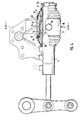
- the master cylinder 1 with a series of outgoing signals only indicated schematically Hydraulic lines 2, 3 and 4 is placed on the outside of its circumference Spherical bearing suspended on the chassis 5 of a truck so that he who its piston rod 6 is articulated to the steering column lever 7, the movements follow the steering column lever of the front axle and around the gimbal Suspension can pivot.
- a spherical bearing 8 placed on its outer circumference is provided. This Spherical bearing 8 sits on a welded onto the master cylinder jacket 9 Fastening tube 10.
- spherical cap rings 11 which by one of one Spacer ring 12 filled gap 13 are separated, and the spherical cap rings 11th surrounding, a bearing shell for these counter rings 14.
- the counter rings 14 are provided with a lubrication hole 15 in the area of the parting plane of the rings, which in turn has a lubricating nipple 16 surrounding the counter rings and supporting tube 17 is aligned.
- the support tube 17 is attached to an L-shaped holder 23 on the chassis 5 Using a hanger pin 24 and a series of mounting screws that are only indicated in Fig. 2, rigidly attached, the attachment by Gusset plates 25 is stiffened on the support tube 17, on the suspension sleeve 26 and are welded to the holder 23.
- the spherical bearing 8 is by flexible sealing sleeves 27, the respective adjacent ends of the mounting tube 10 and of the support tube 17 are applied and clamped there, sealed.
- the spherical bearing 8 ' is in turn seated on the master cylinder jacket 9 a nut 9a screwed mounting tube 10 '. It includes the spherical cap section 11 'with the counter rings 14'.
- the counter rings 14 ' are in the range of Parting plane again provided with a lubrication hole 15, which in turn with a grease nipple 16 of a surrounding and holding the counter rings 14 ' Support tube 17 is aligned.
- the spherical cap section 11 ' is on the fastening tube 10' molded and the counter rings 14 'are fixed by a threaded ring 19, the is screwed onto the internal thread section 32 of the support tube 17.
- a lock is additionally installed to prevent the master cylinder 1 from rotating, which from a screw 28 in a bore of the support tube 17, one Spring 29 and a ball 30 is made. To the gimbal movement of the master cylinder not to restrict with the ball 30, this is in the center of rotation in one axially parallel groove 31 of the spherical cap section 11 '.
Landscapes
- Engineering & Computer Science (AREA)
- Chemical & Material Sciences (AREA)
- Combustion & Propulsion (AREA)
- Transportation (AREA)
- Mechanical Engineering (AREA)
- Support Of The Bearing (AREA)
- Pivots And Pivotal Connections (AREA)
- Power Steering Mechanism (AREA)
- Acyclic And Carbocyclic Compounds In Medicinal Compositions (AREA)
Applications Claiming Priority (2)
| Application Number | Priority Date | Filing Date | Title |
|---|---|---|---|
| DE29622440U DE29622440U1 (de) | 1996-12-30 | 1996-12-30 | Hydraulische Lenkung |
| DE29622440U | 1996-12-30 |
Publications (2)
| Publication Number | Publication Date |
|---|---|
| EP0850819A1 true EP0850819A1 (fr) | 1998-07-01 |
| EP0850819B1 EP0850819B1 (fr) | 2001-07-04 |
Family
ID=8033814
Family Applications (1)
| Application Number | Title | Priority Date | Filing Date |
|---|---|---|---|
| EP97122001A Expired - Lifetime EP0850819B1 (fr) | 1996-12-30 | 1997-12-13 | Direction hydraulique |
Country Status (2)
| Country | Link |
|---|---|
| EP (1) | EP0850819B1 (fr) |
| DE (2) | DE29622440U1 (fr) |
Citations (5)
| Publication number | Priority date | Publication date | Assignee | Title |
|---|---|---|---|---|
| DE662749C (de) * | 1938-07-20 | Ehrenreich & Cie A | Hydraulische Lenkvorrichtung fuer Raeder mit Schwingachsen | |
| US3444936A (en) * | 1966-09-19 | 1969-05-20 | Caterpillar Tractor Co | Motor grader blade adjusting mechanism |
| US4031967A (en) * | 1976-06-14 | 1977-06-28 | Caterpillar Tractor Co. | Motor grader with spherical bearing mounting for blade tilt cylinders |
| US4475615A (en) * | 1982-08-16 | 1984-10-09 | Massey-Ferguson Inc. | Power steering system |
| EP0477816A2 (fr) * | 1990-09-24 | 1992-04-01 | Josef Paul | Direction hydraulique pour essieux de véhicules |
-
1996
- 1996-12-30 DE DE29622440U patent/DE29622440U1/de not_active Expired - Lifetime
-
1997
- 1997-12-13 EP EP97122001A patent/EP0850819B1/fr not_active Expired - Lifetime
- 1997-12-13 DE DE59703951T patent/DE59703951D1/de not_active Expired - Fee Related
Patent Citations (5)
| Publication number | Priority date | Publication date | Assignee | Title |
|---|---|---|---|---|
| DE662749C (de) * | 1938-07-20 | Ehrenreich & Cie A | Hydraulische Lenkvorrichtung fuer Raeder mit Schwingachsen | |
| US3444936A (en) * | 1966-09-19 | 1969-05-20 | Caterpillar Tractor Co | Motor grader blade adjusting mechanism |
| US4031967A (en) * | 1976-06-14 | 1977-06-28 | Caterpillar Tractor Co. | Motor grader with spherical bearing mounting for blade tilt cylinders |
| US4475615A (en) * | 1982-08-16 | 1984-10-09 | Massey-Ferguson Inc. | Power steering system |
| EP0477816A2 (fr) * | 1990-09-24 | 1992-04-01 | Josef Paul | Direction hydraulique pour essieux de véhicules |
Also Published As
| Publication number | Publication date |
|---|---|
| EP0850819B1 (fr) | 2001-07-04 |
| DE29622440U1 (de) | 1997-03-06 |
| DE59703951D1 (de) | 2001-08-09 |
Similar Documents
| Publication | Publication Date | Title |
|---|---|---|
| DE19932678B4 (de) | Stabilisatorgestänge und Gelenk hierfür | |
| DE3922858C2 (fr) | ||
| EP0290587B1 (fr) | Suspension indépendante pour un véhicule, particulièrement pour un autobus | |
| DE10032961B4 (de) | Drehstabfeder | |
| DE19653148A1 (de) | Teleskopisch einfederbare Radführung | |
| DE1199144B (de) | Unabhaengige Radaufhaengung fuer Kraftfahrzeuge | |
| EP0494393A1 (fr) | Suspension de roue indépendante | |
| DE102004002432B4 (de) | Karosserieseitige Lagerung eines Federbeins einer Radaufhängung für Fahrzeuge | |
| DE3728356A1 (de) | Steuerbare antriebsachse | |
| DE102004014555A1 (de) | Radaufhängung für ein lenkbares Fahrzeugrad | |
| EP1557339B1 (fr) | Suspension de roues avants indépendantes et directrices de véhicule industriel | |
| DE9305633U1 (de) | Vorrichtung zum Antreiben, Führen und Lenken eines Fahrzeugrades | |
| DE2820585C2 (de) | Unabhängige Aufhängung der lenkbaren Vorderräder von Kraftfahrzeugen | |
| EP1034949B1 (fr) | Bras de suspension pour une suspension de roue d'un véhicule automobile | |
| DE4215627C1 (en) | Bearing for car wheel track rod - has axial bearing bush member formed as part of bearing bush assembly, which has clamping ring and engages another busy part | |
| DE3402272C2 (de) | Achsbrücke für Kraftfahrzeuge, insbesondere für antreibbare Achsen von Nutzfahrzeugen | |
| EP0132597B1 (fr) | Articulation de barres de direction | |
| DE19730405C1 (de) | Elastisches Lager, insbesondere elastisches Fahrwerkslager für Kraftfahrzeuge | |
| EP3649038A1 (fr) | Dispositif de réglage pour un châssis de véhicule à moteur, et direction d'essieu arrière | |
| DE2217114C3 (de) | Lenkgestänge | |
| DE102018107774A1 (de) | Gelenklager für ein Radmodul eines Kraftfahrzeugs | |
| EP0850819A1 (fr) | Direction hydraulique | |
| AT390763B (de) | Radaufhaengung fuer fahrzeuge | |
| DE3918359A1 (de) | Radaufhaengung fuer fahrzeuge | |
| DE4327703A1 (de) | Winkelgelenk für Fahrwerksteile in einem Kraftfahrzeug |
Legal Events
| Date | Code | Title | Description |
|---|---|---|---|
| PUAI | Public reference made under article 153(3) epc to a published international application that has entered the european phase |
Free format text: ORIGINAL CODE: 0009012 |
|
| AK | Designated contracting states |
Kind code of ref document: A1 Designated state(s): CH DE FR IT LI SE |
|
| AX | Request for extension of the european patent |
Free format text: AL;LT;LV;MK;RO;SI |
|
| 17P | Request for examination filed |
Effective date: 19981201 |
|
| AKX | Designation fees paid |
Free format text: CH DE FR IT LI SE |
|
| RBV | Designated contracting states (corrected) |
Designated state(s): CH DE FR IT LI SE |
|
| 17Q | First examination report despatched |
Effective date: 20000518 |
|
| GRAG | Despatch of communication of intention to grant |
Free format text: ORIGINAL CODE: EPIDOS AGRA |
|
| GRAG | Despatch of communication of intention to grant |
Free format text: ORIGINAL CODE: EPIDOS AGRA |
|
| GRAH | Despatch of communication of intention to grant a patent |
Free format text: ORIGINAL CODE: EPIDOS IGRA |
|
| GRAH | Despatch of communication of intention to grant a patent |
Free format text: ORIGINAL CODE: EPIDOS IGRA |
|
| GRAA | (expected) grant |
Free format text: ORIGINAL CODE: 0009210 |
|
| AK | Designated contracting states |
Kind code of ref document: B1 Designated state(s): CH DE FR IT LI SE |
|
| REG | Reference to a national code |
Ref country code: CH Ref legal event code: NV Representative=s name: ISLER & PEDRAZZINI AG Ref country code: CH Ref legal event code: EP |
|
| REF | Corresponds to: |
Ref document number: 59703951 Country of ref document: DE Date of ref document: 20010809 |
|
| ITF | It: translation for a ep patent filed | ||
| ET | Fr: translation filed | ||
| PGFP | Annual fee paid to national office [announced via postgrant information from national office to epo] |
Ref country code: FR Payment date: 20011207 Year of fee payment: 5 |
|
| PGFP | Annual fee paid to national office [announced via postgrant information from national office to epo] |
Ref country code: CH Payment date: 20011224 Year of fee payment: 5 |
|
| PGFP | Annual fee paid to national office [announced via postgrant information from national office to epo] |
Ref country code: SE Payment date: 20011227 Year of fee payment: 5 |
|
| PLBE | No opposition filed within time limit |
Free format text: ORIGINAL CODE: 0009261 |
|
| STAA | Information on the status of an ep patent application or granted ep patent |
Free format text: STATUS: NO OPPOSITION FILED WITHIN TIME LIMIT |
|
| 26N | No opposition filed | ||
| PG25 | Lapsed in a contracting state [announced via postgrant information from national office to epo] |
Ref country code: SE Free format text: LAPSE BECAUSE OF NON-PAYMENT OF DUE FEES Effective date: 20021214 |
|
| PG25 | Lapsed in a contracting state [announced via postgrant information from national office to epo] |
Ref country code: LI Free format text: LAPSE BECAUSE OF NON-PAYMENT OF DUE FEES Effective date: 20021231 Ref country code: CH Free format text: LAPSE BECAUSE OF NON-PAYMENT OF DUE FEES Effective date: 20021231 |
|
| EUG | Se: european patent has lapsed | ||
| REG | Reference to a national code |
Ref country code: CH Ref legal event code: PL |
|
| PG25 | Lapsed in a contracting state [announced via postgrant information from national office to epo] |
Ref country code: FR Free format text: LAPSE BECAUSE OF NON-PAYMENT OF DUE FEES Effective date: 20030901 |
|
| REG | Reference to a national code |
Ref country code: FR Ref legal event code: ST |
|
| PG25 | Lapsed in a contracting state [announced via postgrant information from national office to epo] |
Ref country code: IT Free format text: LAPSE BECAUSE OF NON-PAYMENT OF DUE FEES;WARNING: LAPSES OF ITALIAN PATENTS WITH EFFECTIVE DATE BEFORE 2007 MAY HAVE OCCURRED AT ANY TIME BEFORE 2007. THE CORRECT EFFECTIVE DATE MAY BE DIFFERENT FROM THE ONE RECORDED. Effective date: 20051213 |
|
| PGFP | Annual fee paid to national office [announced via postgrant information from national office to epo] |
Ref country code: DE Payment date: 20061220 Year of fee payment: 10 |
|
| PG25 | Lapsed in a contracting state [announced via postgrant information from national office to epo] |
Ref country code: DE Free format text: LAPSE BECAUSE OF NON-PAYMENT OF DUE FEES Effective date: 20080701 |