EP0850868A1 - Vorrichtung für den gesteuerten Nothalt von Aufzügen - Google Patents
Vorrichtung für den gesteuerten Nothalt von Aufzügen Download PDFInfo
- Publication number
- EP0850868A1 EP0850868A1 EP97122041A EP97122041A EP0850868A1 EP 0850868 A1 EP0850868 A1 EP 0850868A1 EP 97122041 A EP97122041 A EP 97122041A EP 97122041 A EP97122041 A EP 97122041A EP 0850868 A1 EP0850868 A1 EP 0850868A1
- Authority
- EP
- European Patent Office
- Prior art keywords
- emergency stop
- elevator
- motor
- control
- drive
- Prior art date
- Legal status (The legal status is an assumption and is not a legal conclusion. Google has not performed a legal analysis and makes no representation as to the accuracy of the status listed.)
- Granted
Links
- 238000010586 diagram Methods 0.000 description 6
- 230000001172 regenerating effect Effects 0.000 description 5
- 238000004804 winding Methods 0.000 description 4
- 208000027418 Wounds and injury Diseases 0.000 description 2
- 230000006378 damage Effects 0.000 description 2
- 208000014674 injury Diseases 0.000 description 2
- XUIMIQQOPSSXEZ-UHFFFAOYSA-N Silicon Chemical compound [Si] XUIMIQQOPSSXEZ-UHFFFAOYSA-N 0.000 description 1
- 230000004913 activation Effects 0.000 description 1
- 230000033228 biological regulation Effects 0.000 description 1
- 239000003990 capacitor Substances 0.000 description 1
- 239000003795 chemical substances by application Substances 0.000 description 1
- 230000001419 dependent effect Effects 0.000 description 1
- 238000001514 detection method Methods 0.000 description 1
- 230000005611 electricity Effects 0.000 description 1
- 230000006698 induction Effects 0.000 description 1
- 230000033001 locomotion Effects 0.000 description 1
- 229910052710 silicon Inorganic materials 0.000 description 1
- 239000010703 silicon Substances 0.000 description 1
- 230000029305 taxis Effects 0.000 description 1
Images

Classifications
-
- B—PERFORMING OPERATIONS; TRANSPORTING
- B66—HOISTING; LIFTING; HAULING
- B66B—ELEVATORS; ESCALATORS OR MOVING WALKWAYS
- B66B5/00—Applications of checking, fault-correcting, or safety devices in elevators
- B66B5/02—Applications of checking, fault-correcting, or safety devices in elevators responsive to abnormal operating conditions
Definitions
- the present invention relates generally Elevator controls and in particular a device for Control of an emergency stop of an elevator.
- the present invention relates to a device for Control of an emergency stop of an elevator car in one Elevator system.
- the elevator system contains one Drive motor, which is coupled to the elevator car, a drive control that is between the drive motor and an electrical alternating current to operate the Drive motor is coupled, and one with the Drive control connected elevator control for control of starting, running and stopping the Elevator car.
- a circuit for controlled emergency stop has one connected to the AC electrical source Power supply input, one for supplying the Elevator control connected to electrical power Control power supply output and one for supply the drive control connected to electrical current Drive control power supply output.
- a Storage means for electrical direct current is with the Power supply input connected to electrical power out of the electrical AC power source store, and is with the control power supply output connected to the elevator control to supply with electrical current.
- a normally open switching device is between the storage means for DC electrical power and the drive control power supply output switched, and is a control means connected to the switching means and has an input to Receiving a power failure signal on the a loss of electrical power at the Represents drive control.
- the control means responds the power failure signal by closing the Switching means to the storage means for electrical Connect DC power to the drive control, where the storage means for electrical direct current Drive means supplied with electrical current and the Elevator control an emergency stop of the drive motor coupled elevator car with a predetermined Deceleration rate controls.
- the drive control contains an inverter with a Output that with the AC motor and with an input connected is. Between the AC electrical source and the input of the inverter are a bridge and a DC connection connected in series, and that Switching means is between the storage means for electrical direct current and the input of the inverter switched. If the drive motor is a DC motor, then the drive control contains a rotor output and a field output connected to the DC motor are, and the switching means connects the rotor output with a rotor of the DC motor and connects in the open position the field exit with a field of the motor and in the closed position the storage means for electrical direct current with the rotor and the field of DC motor.
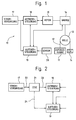
- FIG. 1 shows a prior art elevator system 10, which contains an elevator car 11 arranged so that they are in an elevator shaft (not shown) moved to different floors of a building supply.
- the cabin 11 hangs on one end of a cable 12, which extends over a roller 13 which rotatably on the upper end of the shaft is attached.
- the weight of the Cabin 11 and part of the full passenger load is through a counterweight CW 14 balanced on one opposite end of the cable 12 is attached.
- a Drive means, such as a motor 15, is on conventionally by a brake 16 to the roller 13 coupled to the cabin 11 in the shaft up and to move.
- a power supply 17 is by a Drive control 18 connected to the motor 15 with to supply electrical current.
- a Elevator control means 19 is connected to the power supply 17 connected to a power supply for operation too receive.
- the control means 19 is also with the Drive control 18 and connected to the brake 16 to the Speed of engine 15 and thereby starting, Stop and the speed of movement of the cabin 11 too Taxes.
- the elevator control 19 is also with a Sensor 20 connected, which generates a signal that a Represents an emergency condition requiring the cabin 11 is stopped by the brake 16 for applying a predetermined holding force is activated.
- the Power supply for the circuits in the drive control 18 and the elevator controller 19 from the input lines derives exist after removing the Input power supply, e.g. as a result of one Power failure, no precautions for that Engine control.
- the Input power supply e.g. as a result of one Power failure, no precautions for that Engine control.
- For emergency shutdowns in DC systems connect a resistor module in parallel to the contactors Rotor of the DC motor and switch current in parallel the field coil to apply a braking torque from the motor to provide.
- the system 10 is dependent on the Cabin load with fluctuations in slowdown rates afflicted. For AC induction motors used for Generation of a torque in time-varying fields require, this simple solution is insufficient.
- FIG. 2 shows part of the elevator system 10, including an emergency stop device 21 according to FIG present invention.
- the device 21 is a Circuit system for controlled emergency stop (CESC system, CESC - controlled emergency stop circuit), the one through AC supply lines 22 with an output of Power supply 17 connected input, one through first Power supply lines 23 with one Power supply input of the drive controller 18 connected Has an output and a plurality of inputs and outputs, through the lines 24 with a plurality of out and Inputs of the elevator control 19 are connected.
- the CESC system 21 includes one simple battery supply with high voltage (or Batteries with lower voltage and with Voltage doubler circuits) by the The building's supply lines must be kept charged.
- the entire power supply for the circuits in the Drive control 18 and the elevator control 19 is from this supply so derived that when removing the Main line the control electronics is supplied.
- the system leaves 10 release the brake 16, and the (either from the main line or if necessary from the battery supply powered) drive control tries the cabin 11 with slow down at a predefined rate. Since the controller 18 is fully powered is the speed feedback loop system functional, and the drive has control over the cabin speed in one closed control loop. This enables the system that Brake (in conditions of a light cabin load) with Counteract drive to slow down the slowdown let it be, or with the stopping force of the brake Slipping into an excessively or heavily loaded cabin minimize.
- the CESC system 21 directly applies DC or voltage to the rotor or the field of the motor to regulate the speed of the system.
- the CESC system 21 has the lighter Task, a DC connection of the system to provide and the three-phase inverter part enable that for speed control regulate the required motor AC currents.
- the brake 16 (ideally) for the Keep a percentage of capacity set up and therefore one caused by the drive subsystem Emergency shutdown without activation of the drive system to the failsafe application of the brake leads.
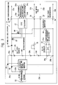
- the CESC system 21 is more detailed in the block diagram from FIG. 3 shown.
- the CESC system 21 includes a Voltage regulator and phase detector module 25, one DC-DC converter supply 26, one Control unit 27 and a charge storage bank 28.
- Das Voltage regulator and phase detector module 25 has three Inputs, each associated with one of the three AC power lines 22 are connected to the Status of incoming power supply lines too monitor and the charge storage bank 28 is on standby hold.
- a first AC supply line 22a is by a first silicon controlled rectifier (SCR) 29 with a positive potential connection 28a Charge storage bank 28 connected.
- a second AC power line 22b is also through a second SCR 30 connected to the positive potential terminal 28a.
- a third AC supply line 22c is included another input of unit 25 and with a negative Potential terminal 28b of the charge storage bank 28 connected.
- the bank 28 can be powered by a plurality of batteries 28c to 28g are formed, with an input of the DC-DC converter supply 26 is due to the battery 28g, which is connected to the terminal 28b.
- An exit from Supply 26 is with a pair of Power supply lines 24a of lines 24 connected to the electronics in the elevator control 19 with electrical To supply electricity.
- the positive potential connection 28a of the CESC 21 is via a Diode 31, a first FET 32 and a first switch 33 through a first one of the power supply lines 23a in series with a power supply part of the drive control 18 switched.
- the negative potential terminal 28b of the CESC 21 is via a second switch 34 by a second one Power supply lines 23b with a power supply part the drive control 18 connected.
- a connection point between batteries 28e and 28f is about one Potentiometer 35 and a third switch 36 by one third of the power supply lines 23c in series with one Field of the motor 15 switched.
- a connection point between the battery 28f and the battery 28g is over a fourth Switch 37 through a fourth of the power supply lines 23d connected to the field of the motor 15.
- the control unit 27 has one with a gate of the first FET 32 connected output and one with the Junction of the first FET and the first Switch 33 connected input on.
- a second FET 38 is between the junction connection of the first FET 32 and the first switch 33 and terminal 28b in series with one Resistor 39 switched.
- the control unit 27 has one further connected to a gate of the second FET 38 Output and one with the junction of the second FET and the resistor 39 connected input.
- the Control unit 27 is coupled so that it switches 33, 34, 36 and 37 actuated.
- the control unit 27 has one Interface with the elevator controller 19 to get a status a drive failure signal on line 24b monitor a status of an emergency shutdown control signal on line 24c to monitor a CESC ready signal to generate on a line 24d, and also around for DC motor applications Velocity voltage reference signal on line 24e to monitor.
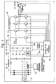
- FIG. 3 shows the CESC system 21, which is a typical one non-regenerative AC inverter elevator drive system 40 was added.
- the AC supply lines 22 are with a Transformer 41 connected to a supply for one to supply electromagnetic brake 16a, and are connected to an input of the full wave bridge 42 to generate a supply direct current.
- An exit from Bridge 42 is connected to a through a DC link 44 Input of an inverter 43 connected to the one Contains choke coil and capacitors.
- the inverter 43 has one connected to an AC motor 45 Exit on.
- In the elevator control 19 puts a lot of control circuit boards 19a represent the electronics that so is switched to operate the inverter 43 and control windings of the motor 45.
- An encoder 46 is connected to the circuit boards 19a to a Provide speed signal that the Speed of the motor 45 represents.
- the CESC system 21 is connected to the output of bridge 42.
- the elevator control system Upon detection of a failure condition in which the Elevator control 19 is still functional, but one If an emergency stop is required, the elevator control system is used simply their existing software and speed loop control, to the speed of the motor 45 with linearly decrease a fixed rate of deceleration. Of the In this way, servo is against the mechanical brake act or this with the slowdown of the cabin 11 a rate that is a physical injury to passengers unlikely to help. In this configuration the CESC system 21 ensures that the power supply the elevator control 19 and the drive control 18 is maintained and this regardless of the failure of the main power supply connected to the power supply lines 22 17 work (voltage drop, Power failure, phase failure, etc.).
- FIG. 5 shows the CESC system 21 connected to a typical DC drive system 47.
- the AC power lines 22 are with an input one DC drive 48 and connected to the CESC system 21.
- An output from the DC drive 48 is through the Switches 33 and 34 with a rotor winding one DC motor 49 connected.
- the AC power lines 22 are also with an entrance connected to a motor field supply 50 (MF supply) has an output by switches 36 and 37 with a motor field winding of the motor 49 are connected.
- MF supply 50 motor field supply
- a Encoder 51 is with a lot of control boards 19b and provides a speed signal, which represents the speed of motor 49.
- the amount of control circuit boards 19b, the electronics in the Elevator control 19 and is switched so that it Operation of the DC drive 48 and control windings of the Motors 49 controls.
- An external potentiometer shown in FIG. 3 potentiometer 35 is connected to connections, those on the CESC system 21 for DC motor field supply are provided.
- a Dissipation resistance network (the one shown in FIG. 3 Resistor 39) with the CESC system 21 for the dissipation of regenerative performance on regenerative systems connected.
- the resistors are the previously in parallel under emergency stop conditions DC motor rotor were switched, now with the CESC system 21 connected to the required controlled To provide motor voltages.
- the CESC system 21 only works to provide one Power supply for all circuit boards 19b and Maintaining the correct charge on the internal Battery bank.
- the CESC system conducts 21 this energy in pulses into the Dissipation resistance bank in order to To control the speed of the engine.
- the CESC control takes pulse energy from the battery banks to the to achieve the required speed control.
- the device for controlling a Emergency stop of the elevator car 11 in the elevator system 10 the following: the one coupled to the elevator car Drive motor 15; the between the drive motor and the AC power supply 17 switched drive control 18 to operate the drive motor; the one with the Drive control connected elevator control 19 for Control the start, run and stop of the Elevator car; the circuit means 21 with the AC power source connected Power supply input, the control power supply output, who is so connected that he Elevator control supplied with electrical power, and that Drive control power supply output that connected so is that he controls the drive with electric current provided; the DC electrical storage means 28 which is connected to the power supply input in order to receive electrical power from the AC power source and store, and with the control power supply output is connected to the To supply elevator control with electric current; the Normally open switching means 33, 34, 36, 37, which between the DC electrical storage means and Drive control power supply output are switched; and the control means 27 connected to the switching means is connected and an input for receiving a Power failure signal that has a loss the electrical power supply at the drive control represents, wherein
- the drive motor 15 is an AC motor, then contains the drive controller 18, the inverter 43, the an output connected to the AC motor and has an entrance.
- the bridge 42 and the DC link 44 are between the AC power source 17 and the input of the inverter in Series connected, and the switching means 33 is between that DC electrical storage means and Inverter input switched.
- the drive motor 15 is a DC motor, then contains the drive control 18 a rotor exit and a field exit, which with the DC motor are connected, and the switching means 33, 34, 36, 37 connect the in the open position Rotor output with a rotor of the DC motor and the Field exit with a field of the engine and in the closed position the electrical DC storage means 28 with the DC motor rotor and field.
Landscapes
- Maintenance And Inspection Apparatuses For Elevators (AREA)
- Elevator Control (AREA)
- Stopping Of Electric Motors (AREA)
Abstract
Description
Claims (6)
- Nothaltvorrichtung für ein Aufzugssystem bestehend aus einem eine Aufzugskabine (11) antreibenden Antriebsmotor (15) mit einer Bremse (16) für einen Nothalt der Aufzugskabine (11), einer den Antriebsmotor (15) steuernden Antriebssteuerung (18), einer mit der Antriebssteuerung (18) verbundenen Aufzugssteuerung (19) zur Steuerung des Aufzugsbetriebes, einem Sensor (20) zum Erfassen eines Nothaltzustandes und einer das Aufzugssystem mit Strom speisenden Stromversorgung (17),
dadurch gekennzeichnet,
dass elektrische Schaltmittel (21) für einen gesteuerten Nothalt der Aufzugskabine (11) mittels Antriebsmotors (15) und/oder Bremse (16) vorgesehen sind. - Nothaltvorrichtung nach Anspruch 1,
dadurch gekennzeichnet,
dass elektrische Schaltmittel (21) für einen Nothalt mit einer vorbestimmten Verzögerung der Aufzugskabine (11) vorgesehen sind. - Nothaltvorrichtung nach Anspruch 2,
dadurch gekennzeichnet,
dass die elektrischen Schaltmittel (21) elektrische Gleichstromspeichermittel (28) für die Notversorgung des Aufzugssystems mit elektrischer Energie aufweisen. - Nothaltvorrichtung nach Anspruch 3,
dadurch gekennzeichnet,
dass Schaltmittel (31, 33) zum Anschalten der Gleichstromspeichermittel (28) an den Motor (15) bei einem Nothalt vorgesehen sind, wobei die Aufzugskabine (11) mittels des Motors (15) nach einer durch die Aufzugssteuerung (19) vorbestimmten Verzögerung entgegen der Bremse (16) antreibbar ist. - Nothaltvorrichtung nach Anspruch 4,
dadurch gekennzeichnet,
dass eine mittels der Gleichstromspeichermittel (28) gespeiste Stromversorgung (26) für die Aufzugssteuerung (19) vorgesehen ist. - Nothaltvorrichtung nach Anspruch 3,
dadurch gekennzeichnet,
dass die elektrischen Schaltmittel (21) eine Steuereinheit (27) und Schalter (33, 34, 36, 37, 38) aufweisen, wobei bei einem Nothalt ein Motorfeld an die Gleichstromspeichermittel (28) schaltbar ist und ein Motoranker bei einem Nothalt an einen Lastwiderstand (39) schaltbar ist und der Strom des Motorankers nach der vorbestimmten Verzögerung steuerbar ist.
Applications Claiming Priority (2)
| Application Number | Priority Date | Filing Date | Title |
|---|---|---|---|
| US08/777,904 US5893432A (en) | 1996-12-31 | 1996-12-31 | Controlled emergency stop apparatus for elevators |
| US777904 | 1996-12-31 |
Publications (2)
| Publication Number | Publication Date |
|---|---|
| EP0850868A1 true EP0850868A1 (de) | 1998-07-01 |
| EP0850868B1 EP0850868B1 (de) | 2006-08-30 |
Family
ID=25111660
Family Applications (1)
| Application Number | Title | Priority Date | Filing Date |
|---|---|---|---|
| EP97122041A Expired - Lifetime EP0850868B1 (de) | 1996-12-31 | 1997-12-15 | Vorrichtung für den gesteuerten Nothalt von Aufzügen |
Country Status (7)
| Country | Link |
|---|---|
| US (1) | US5893432A (de) |
| EP (1) | EP0850868B1 (de) |
| AR (1) | AR013630A1 (de) |
| AT (1) | ATE338005T1 (de) |
| BR (1) | BR9706496A (de) |
| CA (1) | CA2225966C (de) |
| DE (1) | DE59712720D1 (de) |
Cited By (1)
| Publication number | Priority date | Publication date | Assignee | Title |
|---|---|---|---|---|
| EP1363377A3 (de) * | 2002-05-14 | 2014-07-16 | Dewert Antriebs- und Systemtechnik GmbH & Co. KG | Elektromotorischer Stellantrieb |
Families Citing this family (29)
| Publication number | Priority date | Publication date | Assignee | Title |
|---|---|---|---|---|
| JP2001346400A (ja) * | 2000-06-01 | 2001-12-14 | Matsushita Electric Ind Co Ltd | モータブレーキ解除装置 |
| EP1343246A3 (de) * | 2002-03-07 | 2004-02-04 | Innova Patent GmbH | Schaltungsanordnung zur Speisung eines Elektromotors |
| US20040089502A1 (en) * | 2002-11-11 | 2004-05-13 | Angelo Martini | Lift system with reduced power |
| US6802395B1 (en) * | 2003-03-28 | 2004-10-12 | Kone Corporation | System for control and deceleration of elevator during emergency braking |
| US7374020B2 (en) * | 2004-02-27 | 2008-05-20 | Thyssenkrupp Elevator Capital Corporation | Energy efficient elevator system |
| WO2006069591A1 (en) * | 2004-12-31 | 2006-07-06 | Otis Elevator Company | Elevator rescue operation control system |
| US7540356B2 (en) * | 2005-10-18 | 2009-06-02 | Thyssen Elevator Capital Corp. | Method and apparatus to prevent or minimize the entrapment of passengers in elevators during a power failure |
| US7420343B2 (en) * | 2006-08-30 | 2008-09-02 | Westinghouse Electric Co Llc | Current limiting DC motor starter circuit |
| WO2008027052A2 (en) * | 2006-08-31 | 2008-03-06 | Otis Elevator Company | Management of power source variations in an elevator drive system |
| US8146714B2 (en) * | 2006-12-14 | 2012-04-03 | Otis Elevator Company | Elevator system including regenerative drive and rescue operation circuit for normal and power failure conditions |
| FI119508B (fi) * | 2007-04-03 | 2008-12-15 | Kone Corp | Vikaturvallinen tehonohjauslaitteisto |
| EP2303747B1 (de) * | 2008-06-17 | 2013-04-10 | Otis Elevator Company | Sichere steuerung einer bremse unter verwendung von niederleistungssteuerbauelementen |
| KR101218022B1 (ko) * | 2008-06-27 | 2013-01-02 | 미쓰비시덴키 가부시키가이샤 | 엘리베이터 장치 및 그 운전 방법 |
| FI122425B (fi) * | 2010-11-18 | 2012-01-31 | Kone Corp | Sähkönsyötön varmennuspiiri, hissijärjestelmä sekä menetelmä |
| WO2012105986A1 (en) | 2011-02-04 | 2012-08-09 | Otis Elevator Company | Stop sequencing for braking device |
| CN102795524B (zh) * | 2012-07-27 | 2014-07-23 | 石家庄五龙制动器股份有限公司 | 电梯制动系统的abs制动控制电路 |
| EP2956395B1 (de) * | 2013-02-14 | 2020-04-01 | Otis Elevator Company | Regelung der aufzugskabinengeschwindigkeit in einem batteriebetriebenen aufzugssystem |
| FI125316B (fi) * | 2013-09-10 | 2015-08-31 | Kone Corp | Menetelmä hätäpysäytyksen suorittamiseksi sekä hissin turvajärjestely |
| RU2553619C1 (ru) * | 2013-12-06 | 2015-06-20 | Федеральное государственное бюджетное образовательное учреждение высшего профессионального образования "Сибирский государственный индустриальный университет" | Устройство защиты шахтных подъемных установок от проскальзывания каната |
| US10450162B2 (en) | 2015-06-29 | 2019-10-22 | Otis Elevator Company | Electromagnetic brake control circuitry for elevator application |
| US9862568B2 (en) | 2016-02-26 | 2018-01-09 | Otis Elevator Company | Elevator run profile modification for smooth rescue |
| US9809418B2 (en) | 2016-02-29 | 2017-11-07 | Otis Elevator Company | Advanced smooth rescue operation |
| JP6686963B2 (ja) * | 2017-04-27 | 2020-04-22 | 株式会社デンソー | 回転電機制御装置及び制御システム |
| US11053096B2 (en) | 2017-08-28 | 2021-07-06 | Otis Elevator Company | Automatic rescue and charging system for elevator drive |
| US10680538B2 (en) | 2017-09-28 | 2020-06-09 | Otis Elevator Company | Emergency braking for a drive system |
| CN108190678B (zh) * | 2017-12-25 | 2023-06-02 | 佛山市顺德区鼎力电气有限公司 | 一种电梯故障判定方法及智能救援装置 |
| US11866295B2 (en) | 2018-08-20 | 2024-01-09 | Otis Elevator Company | Active braking for immediate stops |
| SE1930360A1 (en) * | 2019-11-04 | 2021-05-05 | Ingemar Carlsson | Deceleration control system for use in a winch, and winch system comprising such a deceleration control system |
| EP3828117B1 (de) * | 2019-11-26 | 2024-02-14 | Otis Elevator Company | Sicherheitsbremsenauslöser |
Citations (6)
| Publication number | Priority date | Publication date | Assignee | Title |
|---|---|---|---|---|
| JPS58207893A (ja) * | 1982-05-25 | 1983-12-03 | Hitachi Ltd | エレベ−タ−制御装置 |
| US4434873A (en) * | 1981-04-09 | 1984-03-06 | Mitsubishi Denki Kabushiki Kaisha | Electric elevator car driving device |
| EP0303717A1 (de) * | 1987-02-26 | 1989-02-22 | Otis Elevator Co | Antriebsregelsystem für einen elektrischen motor. |
| GB2256100A (en) * | 1991-04-22 | 1992-11-25 | Hitachi Ltd | Motor driven door device. |
| EP0630847A2 (de) * | 1993-05-31 | 1994-12-28 | Giovanni Santoro | Notvorrichtung zum Bewegen einer Aufzugskabine zum Stockwerk bei Netzausfall |
| EP0703182A2 (de) * | 1994-09-16 | 1996-03-27 | Kone Oy | Energiesparvorrichtung für einen Aufzug |
Family Cites Families (8)
| Publication number | Priority date | Publication date | Assignee | Title |
|---|---|---|---|---|
| IT1162060B (it) * | 1978-03-17 | 1987-03-18 | Emergenzamatic Srl | Dispositivo automatico statico di emergenza per ascensori e montacarichi |
| JPS5540131A (en) * | 1978-09-08 | 1980-03-21 | Fujitec Kk | Ac elevator controller |
| JPS56103077A (en) * | 1980-01-21 | 1981-08-17 | Mitsubishi Electric Corp | Emergency driving device for elevator |
| JPS5836867A (ja) * | 1981-08-25 | 1983-03-03 | 三菱電機株式会社 | 交流エレベ−タの非常時運転装置 |
| JPS58177864A (ja) * | 1982-04-07 | 1983-10-18 | 株式会社日立製作所 | 交流エレベ−タ−の制御装置 |
| JP2609689B2 (ja) * | 1988-07-19 | 1997-05-14 | 株式会社東芝 | エレベータ装置 |
| US5058710A (en) * | 1990-08-14 | 1991-10-22 | Otis Elevator Company | Elevator power source device |
| JP2656684B2 (ja) * | 1991-06-12 | 1997-09-24 | 三菱電機株式会社 | エレベータの停電時運転装置 |
-
1996
- 1996-12-31 US US08/777,904 patent/US5893432A/en not_active Expired - Lifetime
-
1997
- 1997-12-15 DE DE59712720T patent/DE59712720D1/de not_active Expired - Lifetime
- 1997-12-15 AT AT97122041T patent/ATE338005T1/de active
- 1997-12-15 EP EP97122041A patent/EP0850868B1/de not_active Expired - Lifetime
- 1997-12-29 CA CA002225966A patent/CA2225966C/en not_active Expired - Lifetime
- 1997-12-30 AR ARP970106264A patent/AR013630A1/es active IP Right Grant
- 1997-12-30 BR BR9706496A patent/BR9706496A/pt not_active IP Right Cessation
Patent Citations (6)
| Publication number | Priority date | Publication date | Assignee | Title |
|---|---|---|---|---|
| US4434873A (en) * | 1981-04-09 | 1984-03-06 | Mitsubishi Denki Kabushiki Kaisha | Electric elevator car driving device |
| JPS58207893A (ja) * | 1982-05-25 | 1983-12-03 | Hitachi Ltd | エレベ−タ−制御装置 |
| EP0303717A1 (de) * | 1987-02-26 | 1989-02-22 | Otis Elevator Co | Antriebsregelsystem für einen elektrischen motor. |
| GB2256100A (en) * | 1991-04-22 | 1992-11-25 | Hitachi Ltd | Motor driven door device. |
| EP0630847A2 (de) * | 1993-05-31 | 1994-12-28 | Giovanni Santoro | Notvorrichtung zum Bewegen einer Aufzugskabine zum Stockwerk bei Netzausfall |
| EP0703182A2 (de) * | 1994-09-16 | 1996-03-27 | Kone Oy | Energiesparvorrichtung für einen Aufzug |
Non-Patent Citations (1)
| Title |
|---|
| PATENT ABSTRACTS OF JAPAN vol. 008, no. 059 (E - 232) 17 March 1984 (1984-03-17) * |
Cited By (1)
| Publication number | Priority date | Publication date | Assignee | Title |
|---|---|---|---|---|
| EP1363377A3 (de) * | 2002-05-14 | 2014-07-16 | Dewert Antriebs- und Systemtechnik GmbH & Co. KG | Elektromotorischer Stellantrieb |
Also Published As
| Publication number | Publication date |
|---|---|
| HK1012183A1 (en) | 1999-07-30 |
| BR9706496A (pt) | 1999-03-30 |
| CA2225966C (en) | 2006-05-23 |
| US5893432A (en) | 1999-04-13 |
| EP0850868B1 (de) | 2006-08-30 |
| ATE338005T1 (de) | 2006-09-15 |
| CA2225966A1 (en) | 1998-06-30 |
| DE59712720D1 (de) | 2006-10-12 |
| AR013630A1 (es) | 2001-01-10 |
Similar Documents
| Publication | Publication Date | Title |
|---|---|---|
| EP0850868B1 (de) | Vorrichtung für den gesteuerten Nothalt von Aufzügen | |
| DE69508512T2 (de) | Verfahren und Vorrichtung zum Bremsen eines Synchronmotors | |
| DE3786912T2 (de) | Wechselstrommotor-regelvorrichtung. | |
| DE69031590T2 (de) | Stromversorgungssystem | |
| DE3882902T2 (de) | Wechselstrommotorregelungssystem mit notsteuerung. | |
| DE102012021391B4 (de) | Servomotor-Ansteuervorrichtung, die einen Servomotor steuert, der mit einer Drehwelle verbunden ist | |
| DE112008003996T5 (de) | Treibereinheit | |
| DE3318134C2 (de) | Schutzschaltung für einen Wechselrichter mit Leistungstransistoren | |
| DE112014002438T5 (de) | Motorsteuergerät | |
| DE69021503T2 (de) | Verfahren und Vorrichtung für die Steuerung eines Hubmotors. | |
| DE69102318T2 (de) | Verfahren und Gerät zur Bremsung eines Kurzschlussläufer-Aufzugsmotors bei Störungsfällen, gespeist von einem Frequenzwandler. | |
| DE102014201063A1 (de) | Stromrichterausrüstung | |
| DE112011105328T5 (de) | Fahrstuhl-Steuerungssystem | |
| DE112021006811T5 (de) | Motorantriebsvorrichtung mit ladesteuereinheit | |
| DE69406097T2 (de) | System zur Steuerung der Versorgung eines Asynchronmotors | |
| EP2248253B1 (de) | Generatorvorrichtung mit überspannungsüberwachung | |
| DE10159639A1 (de) | Verfahren und Vorrichtung zur Aufrechterhaltung der Versorgungsspannung einer Stromrichterelektronik während einer Ankerkurzschlussbremsung einer stromrichtergespeisten Drehfeldmaschine | |
| EP1410114B1 (de) | Antriebsanlage mit einrichtung zum geregelten und/oder modulierten absteuern und stillsetzen einer seilbahn | |
| DE2752496A1 (de) | Fahrzeug-schaltungsanordnung fuer fahrt und unabhaengige nutzbremse | |
| DE10135337A1 (de) | Verfahren und Vorrichtung zum Stillsetzen eines Antriebs mit einem matrixumrichter bei Netzausfall | |
| EP3516761B1 (de) | System, umfassend einen ersten wechselrichter und einen zweiten wechselrichter, und ein verfahren zum betreiben des systems | |
| DE2459965A1 (de) | Schaltungsanordnung fuer eine induktionsmaschine | |
| DE112015006655B4 (de) | Schienenfahrzeugsteuervorrichtung | |
| DE2340930A1 (de) | Elektromotor-regelanordnung | |
| DE69504568T2 (de) | Vorrichtung zur Regelung eines Aufzugmotors |
Legal Events
| Date | Code | Title | Description |
|---|---|---|---|
| PUAI | Public reference made under article 153(3) epc to a published international application that has entered the european phase |
Free format text: ORIGINAL CODE: 0009012 |
|
| AK | Designated contracting states |
Kind code of ref document: A1 Designated state(s): AT CH DE FI FR GB LI |
|
| AX | Request for extension of the european patent |
Free format text: AL;LT;LV;MK;RO;SI |
|
| 17P | Request for examination filed |
Effective date: 19981219 |
|
| AKX | Designation fees paid |
Free format text: AT CH DE FI FR GB LI |
|
| RBV | Designated contracting states (corrected) |
Designated state(s): AT CH DE FI FR GB LI |
|
| 17Q | First examination report despatched |
Effective date: 20041228 |
|
| GRAP | Despatch of communication of intention to grant a patent |
Free format text: ORIGINAL CODE: EPIDOSNIGR1 |
|
| GRAS | Grant fee paid |
Free format text: ORIGINAL CODE: EPIDOSNIGR3 |
|
| GRAA | (expected) grant |
Free format text: ORIGINAL CODE: 0009210 |
|
| AK | Designated contracting states |
Kind code of ref document: B1 Designated state(s): AT CH DE FI FR GB LI |
|
| REG | Reference to a national code |
Ref country code: GB Ref legal event code: FG4D Free format text: NOT ENGLISH |
|
| REG | Reference to a national code |
Ref country code: CH Ref legal event code: EP |
|
| REF | Corresponds to: |
Ref document number: 59712720 Country of ref document: DE Date of ref document: 20061012 Kind code of ref document: P |
|
| GBT | Gb: translation of ep patent filed (gb section 77(6)(a)/1977) |
Effective date: 20060925 |
|
| REG | Reference to a national code |
Ref country code: HK Ref legal event code: GR Ref document number: 1012183 Country of ref document: HK |
|
| ET | Fr: translation filed | ||
| PLBE | No opposition filed within time limit |
Free format text: ORIGINAL CODE: 0009261 |
|
| STAA | Information on the status of an ep patent application or granted ep patent |
Free format text: STATUS: NO OPPOSITION FILED WITHIN TIME LIMIT |
|
| 26N | No opposition filed |
Effective date: 20070531 |
|
| REG | Reference to a national code |
Ref country code: FR Ref legal event code: PLFP Year of fee payment: 19 |
|
| REG | Reference to a national code |
Ref country code: FR Ref legal event code: PLFP Year of fee payment: 20 |
|
| PGFP | Annual fee paid to national office [announced via postgrant information from national office to epo] |
Ref country code: CH Payment date: 20161221 Year of fee payment: 20 Ref country code: GB Payment date: 20161222 Year of fee payment: 20 Ref country code: FI Payment date: 20161213 Year of fee payment: 20 Ref country code: DE Payment date: 20161213 Year of fee payment: 20 |
|
| PGFP | Annual fee paid to national office [announced via postgrant information from national office to epo] |
Ref country code: AT Payment date: 20161222 Year of fee payment: 20 Ref country code: FR Payment date: 20161222 Year of fee payment: 20 |
|
| REG | Reference to a national code |
Ref country code: DE Ref legal event code: R071 Ref document number: 59712720 Country of ref document: DE |
|
| REG | Reference to a national code |
Ref country code: CH Ref legal event code: PL |
|
| REG | Reference to a national code |
Ref country code: GB Ref legal event code: PE20 Expiry date: 20171214 |
|
| REG | Reference to a national code |
Ref country code: AT Ref legal event code: MK07 Ref document number: 338005 Country of ref document: AT Kind code of ref document: T Effective date: 20171215 |
|
| PG25 | Lapsed in a contracting state [announced via postgrant information from national office to epo] |
Ref country code: GB Free format text: LAPSE BECAUSE OF EXPIRATION OF PROTECTION Effective date: 20171214 |