EP0851112A1 - Scharnieranordnung, die ein bewegliches Bauteil mit einer, nur einseitig zugänglichen, festen Trägerstruktur verbindet - Google Patents
Scharnieranordnung, die ein bewegliches Bauteil mit einer, nur einseitig zugänglichen, festen Trägerstruktur verbindet Download PDFInfo
- Publication number
- EP0851112A1 EP0851112A1 EP19970403073 EP97403073A EP0851112A1 EP 0851112 A1 EP0851112 A1 EP 0851112A1 EP 19970403073 EP19970403073 EP 19970403073 EP 97403073 A EP97403073 A EP 97403073A EP 0851112 A1 EP0851112 A1 EP 0851112A1
- Authority
- EP
- European Patent Office
- Prior art keywords
- axis
- nut
- fixed
- fixed structure
- movable
- Prior art date
- Legal status (The legal status is an assumption and is not a legal conclusion. Google has not performed a legal analysis and makes no representation as to the accuracy of the status listed.)
- Granted
Links
- 238000011144 upstream manufacturing Methods 0.000 claims description 4
- 210000004027 cell Anatomy 0.000 description 3
- 238000009434 installation Methods 0.000 description 3
- 230000000717 retained effect Effects 0.000 description 3
- 238000004519 manufacturing process Methods 0.000 description 2
- 238000005516 engineering process Methods 0.000 description 1
- 238000009413 insulation Methods 0.000 description 1
- 238000003754 machining Methods 0.000 description 1
- 238000012423 maintenance Methods 0.000 description 1
- 230000002787 reinforcement Effects 0.000 description 1
- 238000010079 rubber tapping Methods 0.000 description 1
Images


Classifications
-
- F—MECHANICAL ENGINEERING; LIGHTING; HEATING; WEAPONS; BLASTING
- F16—ENGINEERING ELEMENTS AND UNITS; GENERAL MEASURES FOR PRODUCING AND MAINTAINING EFFECTIVE FUNCTIONING OF MACHINES OR INSTALLATIONS; THERMAL INSULATION IN GENERAL
- F16C—SHAFTS; FLEXIBLE SHAFTS; ELEMENTS OR CRANKSHAFT MECHANISMS; ROTARY BODIES OTHER THAN GEARING ELEMENTS; BEARINGS
- F16C11/00—Pivots; Pivotal connections
- F16C11/04—Pivotal connections
- F16C11/06—Ball-joints; Other joints having more than one degree of angular freedom, i.e. universal joints
- F16C11/0614—Ball-joints; Other joints having more than one degree of angular freedom, i.e. universal joints the female part of the joint being open on two sides
-
- F—MECHANICAL ENGINEERING; LIGHTING; HEATING; WEAPONS; BLASTING
- F02—COMBUSTION ENGINES; HOT-GAS OR COMBUSTION-PRODUCT ENGINE PLANTS
- F02K—JET-PROPULSION PLANTS
- F02K1/00—Plants characterised by the form or arrangement of the jet pipe or nozzle; Jet pipes or nozzles peculiar thereto
- F02K1/54—Nozzles having means for reversing jet thrust
- F02K1/64—Reversing fan flow
- F02K1/70—Reversing fan flow using thrust reverser flaps or doors mounted on the fan housing
-
- F—MECHANICAL ENGINEERING; LIGHTING; HEATING; WEAPONS; BLASTING
- F16—ENGINEERING ELEMENTS AND UNITS; GENERAL MEASURES FOR PRODUCING AND MAINTAINING EFFECTIVE FUNCTIONING OF MACHINES OR INSTALLATIONS; THERMAL INSULATION IN GENERAL
- F16C—SHAFTS; FLEXIBLE SHAFTS; ELEMENTS OR CRANKSHAFT MECHANISMS; ROTARY BODIES OTHER THAN GEARING ELEMENTS; BEARINGS
- F16C11/00—Pivots; Pivotal connections
- F16C11/02—Trunnions; Crank-pins
-
- F—MECHANICAL ENGINEERING; LIGHTING; HEATING; WEAPONS; BLASTING
- F16—ENGINEERING ELEMENTS AND UNITS; GENERAL MEASURES FOR PRODUCING AND MAINTAINING EFFECTIVE FUNCTIONING OF MACHINES OR INSTALLATIONS; THERMAL INSULATION IN GENERAL
- F16C—SHAFTS; FLEXIBLE SHAFTS; ELEMENTS OR CRANKSHAFT MECHANISMS; ROTARY BODIES OTHER THAN GEARING ELEMENTS; BEARINGS
- F16C2326/00—Articles relating to transporting
- F16C2326/43—Aeroplanes; Helicopters
-
- F—MECHANICAL ENGINEERING; LIGHTING; HEATING; WEAPONS; BLASTING
- F16—ENGINEERING ELEMENTS AND UNITS; GENERAL MEASURES FOR PRODUCING AND MAINTAINING EFFECTIVE FUNCTIONING OF MACHINES OR INSTALLATIONS; THERMAL INSULATION IN GENERAL
- F16C—SHAFTS; FLEXIBLE SHAFTS; ELEMENTS OR CRANKSHAFT MECHANISMS; ROTARY BODIES OTHER THAN GEARING ELEMENTS; BEARINGS
- F16C2360/00—Engines or pumps
-
- Y—GENERAL TAGGING OF NEW TECHNOLOGICAL DEVELOPMENTS; GENERAL TAGGING OF CROSS-SECTIONAL TECHNOLOGIES SPANNING OVER SEVERAL SECTIONS OF THE IPC; TECHNICAL SUBJECTS COVERED BY FORMER USPC CROSS-REFERENCE ART COLLECTIONS [XRACs] AND DIGESTS
- Y10—TECHNICAL SUBJECTS COVERED BY FORMER USPC
- Y10T—TECHNICAL SUBJECTS COVERED BY FORMER US CLASSIFICATION
- Y10T403/00—Joints and connections
- Y10T403/32—Articulated members
- Y10T403/32114—Articulated members including static joint
- Y10T403/32196—Articulate joint is ball and socket
- Y10T403/32204—Articulate joint is ball and socket with threaded joint
-
- Y—GENERAL TAGGING OF NEW TECHNOLOGICAL DEVELOPMENTS; GENERAL TAGGING OF CROSS-SECTIONAL TECHNOLOGIES SPANNING OVER SEVERAL SECTIONS OF THE IPC; TECHNICAL SUBJECTS COVERED BY FORMER USPC CROSS-REFERENCE ART COLLECTIONS [XRACs] AND DIGESTS
- Y10—TECHNICAL SUBJECTS COVERED BY FORMER USPC
- Y10T—TECHNICAL SUBJECTS COVERED BY FORMER US CLASSIFICATION
- Y10T403/00—Joints and connections
- Y10T403/32—Articulated members
- Y10T403/32606—Pivoted
- Y10T403/32631—Universal ball and socket
- Y10T403/32681—Composite ball
Definitions
- the present invention relates to a pivot device ensuring the connection between a movable element displaceable by rotation around its pivots and a fixed structure.
- the invention is applicable to a device for reversing turbojet thrust.
- the turbojet is equipped with a duct behind the blower, the purpose of which is to channel the secondary flow known as cold
- this duct is consisting of an internal wall which surrounds the structure of the motor itself behind the blower, and a external wall whose upstream part comes in continuity with the crankcase that surrounds the blower.
- This outer wall can channel both the secondary flow and the flow primary in its downstream part, and this behind the ejection of the primary flow, called hot, in the case of nacelle with mixed flows or confluent flows for example, but in other cases, the outer wall only channels the secondary flow, in the case of nacelles called flow separated.
- a wall can also cover the outside of the engine, this is to say the outside of the casing that surrounds the blower and the exterior of the exterior wall of the conduit described above, this in order to minimize the drag of the propulsion unit. This is particularly the case for propulsion systems added to the exterior of the aircraft, particularly when these propulsion systems are attached under the wings or at the rear of the fuselage.
- the present invention is applicable to the mounting of an element mobile of a thrust reverser of a type known per se, the mobile element depending on the applications and the type selected inverter being either a door or a grid, either a downstream panel, a shutter or a shell.
- FIG. 1 of the accompanying drawings shows a known example of a such an achievement.
- the moving part of a thrust reverser of turbojet engine consists of doors 2 connected to a fixed upstream structure 1 of inverter and supported so articulated by means of pivots 2a constituted in known manner in itself an axis, a ball joint and a nut.
- pivots 2a constituted in known manner in itself an axis, a ball joint and a nut.
- hatches access are arranged, a hatch 20 on the external side on the upstream fixed structure receiving the axis and a hatch 21 on the side internal on door 2 allowing access to the nut.
- This known solution however has many disadvantages. This in fact results in a large number of parts and a additional manufacturing cost.
- Several interfaces between elements need to be adjusted and impose precautions particular.
- the areas occupied by the access hatches 20 and 21 must be disabled and be made unavailable for other functions such as structural reinforcement or sound insulation.
- One of the aims of the invention is to reduce the number of access hatches and generally to avoid disadvantages of prior known solutions by allowing the installation of a pivot assembly by means of an access only by one side.
- a pivot device characterized in that it comprises an axis mounted on a fixed structural element and assembled with a internal swivel ring arranged on the movable element, a rotation stop and an axial stop being provided on the head of said axis, a single access being provided on the side of the head of the axis and no access being possible at the other end of the axis.
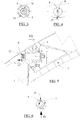
- a pivot member forming housing 3 which the nut 4 is integrated into the inner ring 5, which can be swivel as shown in the figure, is installed on the movable element 2 by the external 6.
- the fixed structure 1 has access 7 for installation and placement of a axis 8 and a locking screw 9.
- the pivoting element 3 is fixed to the mobile structure either by a set of screws 18 or itself threaded and screwed in the mobile structure or any other known assembly of the skilled person.
- the pivoting element 3 may include an eccentricity between the cage 10 and the mobile structure 2, this allows by a rotation of the cage 10 an adjustment in the lines of the mobile structure 2 and fixed structure 1 assembly.
- Axis 8 is mounted in a bore in the structure fixed 1. This one is of such dimension that it allows resumption of effort which pass through it from the structure mobile 2 with fixed structure 1.
- the end receives a machining of adapted shape 16 which marries with the bore of the ring internal 5, the head of the axis 8 being itself retained in rotation with respect to the fixed structure 1.
- the inner ring or ball 5 is integral with the fixed structure 1 and is stopped in rotation allowing mounting and tightening by screw 9.
- the rotation of the mobile structure 2 on the fixed structure 1 being between the cage 10 and the inner ring 5 of the pivoting element 3.
- the assembly between the axis 8 and the ring internal 5 can be done by splines 16, it can be any other known geometric shape or even be made by keying.
- the rotation head stop of the axis 8 as according to figure 4 can be done according to different achievements, fixed 17 or reported, allowing a stop in several positions of the axis or in only one depending on the number of serrations retained.
- a screw 9 crosses the axis 8 and allows the removal of all clearance between the inner ring 5 on the structure 1.
- the latter can be stopped in rotation by a removable assembly 12 and removable covering the head and fixed on the fixed structure 1.
- the inner ring 5 can at the level of its tapping include a geometric deformation making it self-locking.
- the screw 9 may be of sufficient size to resume the efforts which pass from the mobile structure 2 towards the fixed structure 1, in this case the axis 8 can be deleted.
- the inner ring 5 can stop rotating make by embedding part 15 of the ring having a suitable shape in a housing made in the structure fixed 1,
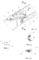
- Figure 6 gives a non-limiting example in its production.
- the arrow 11 shows the mounting direction of the mobile structure 2 on the fixed structure 1 relative to the embedding selected.
- an axis 13 identical in design to axis 8 but not comprising no central hole (with or without grooves) can be used. Maintaining the axis in place can be achieved either by an attached part fixed in the internal part of access 7 or other example as shown in the figure where the access hatch 14 itself serves as a stop.
- the nut 4 integrated into the ball joint 5 is positioned in an imprint 22 of suitable shape to receive the geometric definition retained from said nut.
- This fingerprint can be replaced, for example, by a local stop subject to the structure of the pivot fitting 21 of door 2.
- the part receiving the impression or the stop can be carried out in a veil integrated into the fitting as shown in the figure or be reported on one of the parts of the door structure 2.
- a minimum clearance can be provided between nut 4 and the cavity 22 to allow a slight differential movement between these two pieces.
- the fixing of the door 2 on the fixed structure 1 can be either by an axis 8 and its screw 9 or by a screw 9 single as shown in Figure 5.
- Figures 10 to 12 show an embodiment of the invention using a known type of ball joint.
- the nut 23 is independent of the element of pivoting 3.
- An imprint 22, of a type identical to that already defined, receives part of the nut 23, this for stop rotating the nut.
- a permanent support system of the nut 23 in the cavity 22 is added to the system.
- This can be any type of restraint known to those skilled in the art for this kind of technology, as proposed as an example on the figure, a spring 24 of specific shape allows the maintenance of the nut 23 in its housing 22 while allowing a freedom of movement of said nut.
- door 2 on the fixed structure 1 can be made indifferently by an axis 8 and its screw 9 or by a single screw 9 as shown in FIG. 5.
- any assembly according to the invention can be made from inside the door 2.
- the axis head 8, 9 or 12 blocks the ball 5 on the fixed structure 1 and the hatch 14 or 20 is then placed on the door 2.
Landscapes
- Engineering & Computer Science (AREA)
- General Engineering & Computer Science (AREA)
- Mechanical Engineering (AREA)
- Chemical & Material Sciences (AREA)
- Combustion & Propulsion (AREA)
- Pivots And Pivotal Connections (AREA)
Applications Claiming Priority (2)
| Application Number | Priority Date | Filing Date | Title |
|---|---|---|---|
| FR9616031A FR2757913B1 (fr) | 1996-12-26 | 1996-12-26 | Dispositif de pivot entre un element mobile et une structure fixe accessible d'un seul cote |
| FR9616031 | 1996-12-26 |
Publications (2)
| Publication Number | Publication Date |
|---|---|
| EP0851112A1 true EP0851112A1 (de) | 1998-07-01 |
| EP0851112B1 EP0851112B1 (de) | 2003-07-23 |
Family
ID=9499151
Family Applications (1)
| Application Number | Title | Priority Date | Filing Date |
|---|---|---|---|
| EP19970403073 Expired - Lifetime EP0851112B1 (de) | 1996-12-26 | 1997-12-18 | Scharnieranordnung, die ein bewegliches Bauteil mit einer, nur einseitig zugänglichen, festen Trägerstruktur verbindet |
Country Status (8)
| Country | Link |
|---|---|
| US (1) | US5947625A (de) |
| EP (1) | EP0851112B1 (de) |
| JP (1) | JPH10196457A (de) |
| CA (1) | CA2225618A1 (de) |
| DE (1) | DE69723662T2 (de) |
| FR (1) | FR2757913B1 (de) |
| RU (1) | RU2156873C2 (de) |
| WO (1) | WO1998029655A1 (de) |
Families Citing this family (13)
| Publication number | Priority date | Publication date | Assignee | Title |
|---|---|---|---|---|
| DE102004029581B4 (de) * | 2004-06-18 | 2014-01-16 | Zf Friedrichshafen Ag | Zentralgelenk für einen Dreieckslenker von Kraftfahrzeugen |
| FR2887930B1 (fr) * | 2005-06-30 | 2007-08-17 | Snecma | Systeme de detection de fermeture et de verrouillage pour inverseur de poussee de turboreacteur |
| US8015797B2 (en) | 2006-09-21 | 2011-09-13 | Jean-Pierre Lair | Thrust reverser nozzle for a turbofan gas turbine engine |
| US8172175B2 (en) | 2007-11-16 | 2012-05-08 | The Nordam Group, Inc. | Pivoting door thrust reverser for a turbofan gas turbine engine |
| US8091827B2 (en) | 2007-11-16 | 2012-01-10 | The Nordam Group, Inc. | Thrust reverser door |
| US7735778B2 (en) | 2007-11-16 | 2010-06-15 | Pratt & Whitney Canada Corp. | Pivoting fairings for a thrust reverser |
| US8051639B2 (en) | 2007-11-16 | 2011-11-08 | The Nordam Group, Inc. | Thrust reverser |
| US8052085B2 (en) | 2007-11-16 | 2011-11-08 | The Nordam Group, Inc. | Thrust reverser for a turbofan gas turbine engine |
| US8052086B2 (en) | 2007-11-16 | 2011-11-08 | The Nordam Group, Inc. | Thrust reverser door |
| US7704029B2 (en) * | 2007-11-19 | 2010-04-27 | Pratt & Whitney Canada Corp. | Arrangement for releasably holding a component in a fixed position on a shaft |
| RU2451194C1 (ru) * | 2010-12-02 | 2012-05-20 | Открытое акционерное общество "Научно-производственное объединение "Сатурн" (ОАО "НПО "Сатурн") | Регулируемое сопло турбореактивного двигателя |
| CN104613061B (zh) * | 2013-11-01 | 2018-09-04 | 空中客车简化股份公司 | 承弯接头和飞行器 |
| FR3078108B1 (fr) * | 2018-02-20 | 2020-01-31 | Safran Nacelles | Ensemble propulsif comportant des points de levage disposes sur des supports de verins d’inverseur de poussee |
Citations (2)
| Publication number | Priority date | Publication date | Assignee | Title |
|---|---|---|---|---|
| EP0315522A1 (de) * | 1987-11-05 | 1989-05-10 | HISPANO-SUIZA Société anonyme dite: | Schubdüse mit Schubumkehrvorrichtung mittels Klappen und mit veränderbarem Querschnitt |
| US5101928A (en) * | 1990-04-27 | 1992-04-07 | Avco Corporation | Power pack suspension system |
Family Cites Families (10)
| Publication number | Priority date | Publication date | Assignee | Title |
|---|---|---|---|---|
| US2974986A (en) * | 1956-08-10 | 1961-03-14 | Gen Motors Corp | Bushing |
| US3482890A (en) * | 1966-04-27 | 1969-12-09 | Alfred A Burrell | Bearing |
| DE2241817C3 (de) * | 1972-08-25 | 1975-04-03 | Motoren- Und Turbinen-Union Muenchen Gmbh, 8000 Muenchen | Schubumkehrvorrichtung für ein mit einer Nachverbrennungsanlage ausgerüstetes Turbinenstrahltriebwerk eines Flugzeugs |
| SU898139A1 (ru) * | 1976-07-01 | 1982-01-15 | Предприятие П/Я А-3395 | Шарнирное соединение |
| US4552309A (en) * | 1982-04-07 | 1985-11-12 | Rolls-Royce Inc. | Variable geometry nozzles for turbomachines |
| US4705422A (en) * | 1986-08-08 | 1987-11-10 | Cbc Industries, Inc. | Multi-position fixture |
| RU1563310C (ru) * | 1988-04-19 | 1994-05-15 | Акционерное общество "Авиадвигатель" | Реверсивное устройство наружного контура турбореактивного двухконтурного двигателя |
| SE467456B (sv) * | 1988-10-20 | 1992-07-20 | Onspot Ab | Armlagring vid slirskydd |
| FR2638207B1 (fr) * | 1988-10-20 | 1990-11-30 | Hispano Suiza Sa | Inverseur de poussee de turboreacteur, a portes pivotantes equilibrees |
| RU2049274C1 (ru) * | 1992-06-29 | 1995-11-27 | Алексей Андреевич Бутаков | Шарнир бутакова |
-
1996
- 1996-12-26 FR FR9616031A patent/FR2757913B1/fr not_active Expired - Fee Related
-
1997
- 1997-12-15 CA CA 2225618 patent/CA2225618A1/fr not_active Abandoned
- 1997-12-18 WO PCT/FR1997/002339 patent/WO1998029655A1/fr not_active Ceased
- 1997-12-18 RU RU98117820A patent/RU2156873C2/ru active
- 1997-12-18 EP EP19970403073 patent/EP0851112B1/de not_active Expired - Lifetime
- 1997-12-18 DE DE1997623662 patent/DE69723662T2/de not_active Expired - Fee Related
- 1997-12-23 US US08/997,506 patent/US5947625A/en not_active Expired - Fee Related
- 1997-12-26 JP JP36123597A patent/JPH10196457A/ja active Pending
Patent Citations (2)
| Publication number | Priority date | Publication date | Assignee | Title |
|---|---|---|---|---|
| EP0315522A1 (de) * | 1987-11-05 | 1989-05-10 | HISPANO-SUIZA Société anonyme dite: | Schubdüse mit Schubumkehrvorrichtung mittels Klappen und mit veränderbarem Querschnitt |
| US5101928A (en) * | 1990-04-27 | 1992-04-07 | Avco Corporation | Power pack suspension system |
Also Published As
| Publication number | Publication date |
|---|---|
| CA2225618A1 (fr) | 1998-06-26 |
| JPH10196457A (ja) | 1998-07-28 |
| DE69723662D1 (de) | 2003-08-28 |
| RU2156873C2 (ru) | 2000-09-27 |
| FR2757913A1 (fr) | 1998-07-03 |
| FR2757913B1 (fr) | 1999-01-29 |
| US5947625A (en) | 1999-09-07 |
| DE69723662T2 (de) | 2004-07-01 |
| EP0851112B1 (de) | 2003-07-23 |
| WO1998029655A1 (fr) | 1998-07-09 |
Similar Documents
| Publication | Publication Date | Title |
|---|---|---|
| EP0851112B1 (de) | Scharnieranordnung, die ein bewegliches Bauteil mit einer, nur einseitig zugänglichen, festen Trägerstruktur verbindet | |
| EP0861978B1 (de) | Schubumkehrvorrichtung mit synchronisierten Klappenstellantrieben | |
| EP0846854B1 (de) | Schubumkehrvorrichtung für Strahltriebwerke mittels Klappen, die mit der Gondelfläche fluchten | |
| EP0851111B1 (de) | Schubumkehrvorrichtung für ein Strahltriebwerk mit Klappe am Hinterteil | |
| CA2780058A1 (fr) | Ensemble pour turboreacteur d'aeronef comprenant un capot d'inversion de pousee | |
| CA2240094A1 (fr) | Turboreacteur a double flux associe a un inverseur de poussee avec un carenage rapporte dans la veine fluide | |
| EP2331404B1 (de) | Vorrichtung zur zentrierung einer lufteinlassstruktur auf der zentralstruktur einer gondel | |
| CA2814384A1 (fr) | Inverseur de poussee pour turboreacteur d'aeronef, a nombre d'actionneurs reduit | |
| EP0764779A1 (de) | Schubumkehrvorrichtung mit einem mit Primärteil verbundenen Klappen | |
| EP1092859A1 (de) | Schubumkehrvorrichtung für ein Strahltriebwerk | |
| EP0835999B1 (de) | Schubumkehrvorrichtung mit optimalisierter Anordnung des Betätigungsorgans | |
| EP2971730B1 (de) | In eine sperreinrichtung einer schubumkehrvorrichtung integrierte mechanische hemmvorrichtung | |
| FR2760788A1 (fr) | Inverseur de poussee de turboreacteur a portes a structure externe plaquee | |
| FR2760789A1 (fr) | Inverseur de poussee de turboreacteur a portes a structure externe autoraidie | |
| CA2242005A1 (fr) | Bloc hydraulique muni d'un systeme de montage de securite de branchement | |
| EP3472452B1 (de) | Schubumkehrvorrichtung mit axialer einstellung der verschiebbaren haube | |
| FR3078951A1 (fr) | Turboreacteur comportant une nacelle equipee d'un carter de soufflante et d'une structure fixe | |
| FR2769953A1 (fr) | Inverseur de poussee de turboreacteur a portes associees a un panneau amont balance a retenue laterale | |
| FR3146944A1 (fr) | Dispositif d’articulation pour la rotation d’une piece d’une turbomachine d’aeronef | |
| EP3696088A1 (de) | Gondel eines turboreaktors, die eine blockiertür und ein system zum einsatz einer solchen blockiertür umfasst |
Legal Events
| Date | Code | Title | Description |
|---|---|---|---|
| PUAI | Public reference made under article 153(3) epc to a published international application that has entered the european phase |
Free format text: ORIGINAL CODE: 0009012 |
|
| 17P | Request for examination filed |
Effective date: 19980113 |
|
| AK | Designated contracting states |
Kind code of ref document: A1 Designated state(s): DE FR GB IT |
|
| AX | Request for extension of the european patent |
Free format text: AL;LT;LV;MK;RO;SI |
|
| AKX | Designation fees paid |
Free format text: DE FR GB IT |
|
| RBV | Designated contracting states (corrected) |
Designated state(s): DE FR GB IT |
|
| 17Q | First examination report despatched |
Effective date: 20020612 |
|
| GRAH | Despatch of communication of intention to grant a patent |
Free format text: ORIGINAL CODE: EPIDOS IGRA |
|
| GRAH | Despatch of communication of intention to grant a patent |
Free format text: ORIGINAL CODE: EPIDOS IGRA |
|
| GRAA | (expected) grant |
Free format text: ORIGINAL CODE: 0009210 |
|
| RAP1 | Party data changed (applicant data changed or rights of an application transferred) |
Owner name: HUREL HISPANO LE HAVRE |
|
| AK | Designated contracting states |
Designated state(s): DE FR GB IT |
|
| REG | Reference to a national code |
Ref country code: GB Ref legal event code: FG4D Free format text: NOT ENGLISH |
|
| REF | Corresponds to: |
Ref document number: 69723662 Country of ref document: DE Date of ref document: 20030828 Kind code of ref document: P |
|
| GBT | Gb: translation of ep patent filed (gb section 77(6)(a)/1977) |
Effective date: 20031006 |
|
| PG25 | Lapsed in a contracting state [announced via postgrant information from national office to epo] |
Ref country code: GB Free format text: LAPSE BECAUSE OF NON-PAYMENT OF DUE FEES Effective date: 20031218 |
|
| PLBE | No opposition filed within time limit |
Free format text: ORIGINAL CODE: 0009261 |
|
| STAA | Information on the status of an ep patent application or granted ep patent |
Free format text: STATUS: NO OPPOSITION FILED WITHIN TIME LIMIT |
|
| PG25 | Lapsed in a contracting state [announced via postgrant information from national office to epo] |
Ref country code: DE Free format text: LAPSE BECAUSE OF NON-PAYMENT OF DUE FEES Effective date: 20040701 |
|
| 26N | No opposition filed |
Effective date: 20040426 |
|
| GBPC | Gb: european patent ceased through non-payment of renewal fee |
Effective date: 20031218 |
|
| PG25 | Lapsed in a contracting state [announced via postgrant information from national office to epo] |
Ref country code: FR Free format text: LAPSE BECAUSE OF NON-PAYMENT OF DUE FEES Effective date: 20040831 |
|
| REG | Reference to a national code |
Ref country code: FR Ref legal event code: ST |
|
| PG25 | Lapsed in a contracting state [announced via postgrant information from national office to epo] |
Ref country code: IT Free format text: LAPSE BECAUSE OF NON-PAYMENT OF DUE FEES;WARNING: LAPSES OF ITALIAN PATENTS WITH EFFECTIVE DATE BEFORE 2007 MAY HAVE OCCURRED AT ANY TIME BEFORE 2007. THE CORRECT EFFECTIVE DATE MAY BE DIFFERENT FROM THE ONE RECORDED. Effective date: 20051218 |