EP0851160A1 - Flow force compensating method and flow control valve of spool type using the same method - Google Patents
Flow force compensating method and flow control valve of spool type using the same method Download PDFInfo
- Publication number
- EP0851160A1 EP0851160A1 EP97122831A EP97122831A EP0851160A1 EP 0851160 A1 EP0851160 A1 EP 0851160A1 EP 97122831 A EP97122831 A EP 97122831A EP 97122831 A EP97122831 A EP 97122831A EP 0851160 A1 EP0851160 A1 EP 0851160A1
- Authority
- EP
- European Patent Office
- Prior art keywords
- spool
- flow
- valve
- land
- sleeve
- Prior art date
- Legal status (The legal status is an assumption and is not a legal conclusion. Google has not performed a legal analysis and makes no representation as to the accuracy of the status listed.)
- Granted
Links
- 238000000034 method Methods 0.000 title claims abstract description 17
- 239000012530 fluid Substances 0.000 claims abstract description 69
- 230000002706 hydrostatic effect Effects 0.000 claims abstract description 21
- 238000009826 distribution Methods 0.000 description 8
- 230000007935 neutral effect Effects 0.000 description 6
- 230000000694 effects Effects 0.000 description 2
- 230000006866 deterioration Effects 0.000 description 1
- 230000002093 peripheral effect Effects 0.000 description 1
Images



Classifications
-
- F—MECHANICAL ENGINEERING; LIGHTING; HEATING; WEAPONS; BLASTING
- F16—ENGINEERING ELEMENTS AND UNITS; GENERAL MEASURES FOR PRODUCING AND MAINTAINING EFFECTIVE FUNCTIONING OF MACHINES OR INSTALLATIONS; THERMAL INSULATION IN GENERAL
- F16K—VALVES; TAPS; COCKS; ACTUATING-FLOATS; DEVICES FOR VENTING OR AERATING
- F16K11/00—Multiple-way valves, e.g. mixing valves; Pipe fittings incorporating such valves
- F16K11/02—Multiple-way valves, e.g. mixing valves; Pipe fittings incorporating such valves with all movable sealing faces moving as one unit
- F16K11/06—Multiple-way valves, e.g. mixing valves; Pipe fittings incorporating such valves with all movable sealing faces moving as one unit comprising only sliding valves, i.e. sliding closure elements
- F16K11/065—Multiple-way valves, e.g. mixing valves; Pipe fittings incorporating such valves with all movable sealing faces moving as one unit comprising only sliding valves, i.e. sliding closure elements with linearly sliding closure members
- F16K11/07—Multiple-way valves, e.g. mixing valves; Pipe fittings incorporating such valves with all movable sealing faces moving as one unit comprising only sliding valves, i.e. sliding closure elements with linearly sliding closure members with cylindrical slides
-
- F—MECHANICAL ENGINEERING; LIGHTING; HEATING; WEAPONS; BLASTING
- F16—ENGINEERING ELEMENTS AND UNITS; GENERAL MEASURES FOR PRODUCING AND MAINTAINING EFFECTIVE FUNCTIONING OF MACHINES OR INSTALLATIONS; THERMAL INSULATION IN GENERAL
- F16K—VALVES; TAPS; COCKS; ACTUATING-FLOATS; DEVICES FOR VENTING OR AERATING
- F16K39/00—Devices for relieving the pressure on the sealing faces
- F16K39/04—Devices for relieving the pressure on the sealing faces for sliding valves
-
- Y—GENERAL TAGGING OF NEW TECHNOLOGICAL DEVELOPMENTS; GENERAL TAGGING OF CROSS-SECTIONAL TECHNOLOGIES SPANNING OVER SEVERAL SECTIONS OF THE IPC; TECHNICAL SUBJECTS COVERED BY FORMER USPC CROSS-REFERENCE ART COLLECTIONS [XRACs] AND DIGESTS
- Y10—TECHNICAL SUBJECTS COVERED BY FORMER USPC
- Y10T—TECHNICAL SUBJECTS COVERED BY FORMER US CLASSIFICATION
- Y10T137/00—Fluid handling
- Y10T137/0318—Processes
-
- Y—GENERAL TAGGING OF NEW TECHNOLOGICAL DEVELOPMENTS; GENERAL TAGGING OF CROSS-SECTIONAL TECHNOLOGIES SPANNING OVER SEVERAL SECTIONS OF THE IPC; TECHNICAL SUBJECTS COVERED BY FORMER USPC CROSS-REFERENCE ART COLLECTIONS [XRACs] AND DIGESTS
- Y10—TECHNICAL SUBJECTS COVERED BY FORMER USPC
- Y10T—TECHNICAL SUBJECTS COVERED BY FORMER US CLASSIFICATION
- Y10T137/00—Fluid handling
- Y10T137/8593—Systems
- Y10T137/86493—Multi-way valve unit
- Y10T137/86574—Supply and exhaust
- Y10T137/8667—Reciprocating valve
- Y10T137/86694—Piston valve
- Y10T137/8671—With annular passage [e.g., spool]
Definitions
- the present invention relates to a flow force compensating method for a flow control valve having a fluid passage structure in which control fluid flows from a valve stem space, via a control orifice, into a valve land space defined between a spool land and a circumferential groove formed in a sleeve, and such a flow control valve of spool type using the same method.
- Fig. 13 is a sectional view showing an example of a flow control valve using such hydrostatic bearings.
- a spool 1 is slidably mounted within a sleeve S and hydrostatic bearings 19 are provided on both ends of the spool.
- the spool 1 can be shifted to the left or the right from a neutral position as shown by a spool drive means D such as a solenoid, so that a valve opening is adjusted by the position of lands 2, 2a, 2b, thereby controlling flow rates of fluid flowing between ports P, 17 and 18.
- Fig. 11 shows the spool 1 incorporated in the flow control valve stated above.
- the spool 1 has lands 2a and 2, 2b having a large diameter at its central portion and both end portions and stems 3, 3a having small diameter between the lands, and the lands 2, 2b are supported by hydraulic bearings.
- the spool shown in Fig. 11 is a conventional one and is not subjected to flow force compensation which will be described later.
- Fig. 12 shows a condition wherein the spool is shifted from a neutral position to the right so that the fluid flows from a control port 18 to a return port 17.
- Fig. 12 when the fluid flows through a valve stem space 15, different pressure distributions are generated on both end walls defining the valve stem space 15. The difference in pressure distributions creates a so called flow force F acting on the spool 1 which tends to close the valve.
- the flow force sometimes generates self-excited vibration in the spool which deteriorates the valve function.
- an object of the present invention is to provide a flow force compensating method and a flow control valve of spool type, in which desired swirl flow can be generated without making the configuration of a bucket complicated.
- Another object of the present invention is to provide a flow force compensating method and a flow control valve of spool type, wherein a swirl flow for compensating the flow force is positively generated.
- a flow force compensating method for a flow control valve including a sleeve, a spool slidably provided in the sleeve and having a stem and a land, and a fluid passage structure formed in the control valve.
- the fluid passage structure includes a valve stem space formed between the stem and the sleeve, and a valve land space defined between the land and a circumferential groove formed in the sleeve and a control fluid flows from the valve stem space, through a control orifice, into the valve land space.
- a circumferential groove is formed in the land so as to define the valve land space and an auxiliary fluid flow is supplied into the valve land space toward a central axis of the spool from a side opposing to the control orifice, whereby the control fluid is swirled within the valve land space so as to compensate a flow force acting on the spool.
- the auxiliary fluid flow may be provided by a bearing fluid flowing out of a hydrostatic bearing provided between the sleeve and the land of the spool.
- the auxiliary fluid flow can be directed toward the central axis of the spool by positioning an end wall of the circumferential groove formed in the land axially outward of an end wall of the circumferntial groove formed in the sleeve.
- control fluid is swirled within the valve land space in such a way that an axial flow velocity component of the control fluid flow along a bottom surface of the circumferntial groove is greater on the control orifice side than on the opposite side thereof.
- a flow control valve of spool type including a sleeve, a spool slidably provided in the sleeve and having a stem and a land, and a fluid passage structure formed in the control valve.
- the fluid passage structure includes a valve stem space formed between the stem and the sleeve, and a valve land space defined between the land and a circumferential groove formed in the sleeve and a control orifice formed at an end of the land facing the stem space.
- a circumferential groove is formed in the land so as to define the valve land space, and means for supplying an auxiliary fluid flow into the valve land space toward a central axis of the spool from a side opposing to the control orifice is provided, whereby the control fluid is swirled within the valve land space so as to compensate a flow force acting on the spool.
- the auxiliary fluid flow may be provided by a bearing fluid flowing out of a hydrostatic bearing provided between the sleeve and the land of the spool.
- An end wall of the circumferential groove formed in the land can be positioned axially outward of an end wall of the circumferntial groove formed in the sleeve to direct the auxiliary fluid flow toward the central axis of the spool.
- a bottom surface of the circumferential groove formed in the spool land may include a slant surface on the side of the control orifice and an end wall portion on the opposite side thereof, and an angle of the slant surface relative to the spool axis is made smaller than that of the end wall portion.
- the hydrostatic bearing may be a taper land bearing or a stepped bearing.
- the control valve may be a four-way flow control valve including a supply port, a return port and two control ports or a three-way flow control valve including a supply port, a return port and a control port.
- the stable swirl flow can positively be formed with a simple bucket configuration, thereby easily compensating the flow force of the spool.
- the drive means for shifting the spool can be made compact, thereby making the entire spool valve compact and light-weighted.
- valve vibration due to the flow force can be eliminated, and, thus, the valve can be operated stably.
- Fig. 1 is a side view of a spool according to a first embodiment of the present invention.
- Fig. 2 is an enlarged sectional view showing circumferential grooves formed in a spool and a sleeve which form main parts of the present invention.
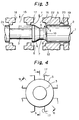
- Fig. 3 is a sectional view taken along A-A in Fig. 4 for explaining a function of the invention.
- Fig. 4 is a cross-sectional view of the spool and the sleeve.
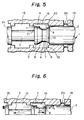
- Fig. 5 is a sectional view taken along B-B in Fig. 4 for explaining a function of the present invention.
- Fig. 6 is a partial view for supplementary explanation of the function of the embodiment shown in Fig 5.
- Fig. 7 is a graph showing characteristics regarding a flow rate and a flow force acting on a conventional spool.
- Fig. 8 is a graph showing characteristics regarding a flow rate and a flow force acting on a spool according to the present invention.
- Fig. 9 is a view showing another embodiment of the present invention.
- Fig. 10 is a view showing a further embodiment of the present invention.
- Fig. 11 is a view showing a conventional spool.
- Fig. 12 is a view for explaining an axial flow force acting on the spool of Fig. 11.
- Fig. 13 is a sectional view of a conventional flow rate control valve of spool type.
- FIG. 1 shows a spool of a flow control valve of spool type according to a first embodiment of the invention.
- a spool generally indicated by the reference numeral 1 has end lands 2, 2b and a central land 2a, and stems 3, 3a formed between the lands, and circumferential grooves 4, 4b are formed in the lands 2, 2b near inner end portions thereof.
- Fig. 2 is a partial enlarged sectional view of the control valve wherein the spool of Fig. 1 is housed in a sleeve S.
- the circumferential groove 4 is formed in the end land 2 near a control orifice portion 21 facing the central land and a straight portion 5 having the same diameter as that of the land 2 is left between the control orifice 21 and the groove 4.
- the circumferential groove 4 is defined by an inclined wall portion 6 of a gentle slope connected to a bottom wall portion 7 of the groove and a groove end wall 10 connected to the bottom wall portion 7 through a curved wall portion 8.
- the groove end wall 10 of the spool circumferential groove 4 is positioned outwardly of a groove end wall 12 of the sleeve S.
- the reference numeral 15 denotes a valve stem space formed at the stem 3; 16 denotes a valve land space formed at the land 2; 17 denotes a return port; 18 denotes a control port; 19 denotes a pocket of a hydrostatic bearing; and 20 denotes a restriction of the hydrostatic bearing.
- Fig. 3 shows a flowing condition of the control fluid in a sectional plane passing through the ports 17, 18 of the sleeve S (section A-A in Fig. 4).
- Pressurized fluid from the control port 18 flows into the valve stem space 15 formed at the spool stem 3 (flow of the pressurized fluid is indicated by the arrow) and then flows into the valve land space 16 formed at the land 2 through the control orifice portion 21 as shown by the arrow f to reach the return port 17.
- the arrow g indicates bearing fluid flow flowing out of the hydrostatic bearings 19 (only one is shown) provided on both ends of the spool into the valve land space 16.
- Fig. 5 shows a flowing condition of the control fluid in a sectional plane not including any port (section B-B in Fig. 4). Since the end wall 10 of the circumferential groove 4 is positioned outwardly of the groove end wall 12 of the sleeve S (i.e., nearer the pocket 19 of the hydrostatic bearing), the bearing fluid flow g is directed toward a central axis of the spool 1.
- control fluid flow h flowing out of the valve stem space 15 through the control orifice portion 21 into the valve land space 16 firstly flows toward a groove end wall 12 of the sleeve along a bottom wall portion 22 of the circumferential groove in the sleeve S and is then pulled radially inwardly by the bearing fluid flow g being directed toward the central axis of the spool to form control fluid flow flowing along the curved wall portion 8, bottom wall portion 7 and inclined wall portion 6. That is to say, a swirl flow is generated in the valve land space 16.
- the bearing fluid flow g being directed toward the central axis of the spool acts as auxiliary flow for assisting swirling of the control fluid flow h.
- the reason why the bearing fluid flow is directed toward the central axis of the spool is that the groove end wall 10 of the circumferential groove 4 of the spool 1 is positioned outwardly of the groove end wall 12 of the sleeve S.
- the curved wall portion 8 formed in the circumferential groove of the spool has a shape for reversing and guiding the fluid flow toward the inclined wall portion 6 and, thus, includes a gentle slope in the vicinity of the bottom wall portion 7 of the groove.
- a projected area of the gentle slope (against which the low pressure distribution acts) in the axial direction is small, a force acting on the gentle slope is substantially the same as that acting on a vertical surface.
- the swirl flow can easily be generated while suppressing a deterioration on the flow force compensating effect.
- Fig. 7 is a graph showing flow rate flow force characteristics of a conventional spool and Fig. 8 is a graph showing the same characteristics of the spool of the present invention.
- the ordinate indicates the flow force and the abscissa indicates the flow rate.
- the flow force is reduced to about 1/4 of the flow force generated in the conventional spool. That is to say, the spool can be shifted by a driving force of about 1/4 of the conventional driving force.
- Figs. 9 and 10 are views showing other embodiments of the present invention, where Fig. 9 shows a taper land bearing in which a taper T is formed on the hydrostatic bearing at the sleeve side and Fig. 10 shows a stepped bearing in which a stepped portion V is formed on the hydrostatic bearing at the sleeve side.
- the spool is maintained in the center of the sleeve.
- the bearing fluid flow g as an auxiliary flow for generating the swirl flow is the same as that in the first embodiment and achieve the same technical effect.
- the taper T or the stepped portion V can be provided on the surface of the spool side.
- the stable swirl flow can positively be formed with a simple bucket configuration, thereby easily compensating the flow force acting on the spool.
- the drive means for shifting the spool can be made compact, thereby making the entire spool valve compact and light-weighted.
- valve vibration due to the flow force can be eliminated, and, thus, the valve can be operated stably.
Landscapes
- Engineering & Computer Science (AREA)
- General Engineering & Computer Science (AREA)
- Mechanical Engineering (AREA)
- Sliding Valves (AREA)
- Multiple-Way Valves (AREA)
- Preventing Unauthorised Actuation Of Valves (AREA)
- Magnetic Bearings And Hydrostatic Bearings (AREA)
Abstract
Description
Claims (10)
- A flow force compensating method for a flow control valve including a sleeve, a spool slidably provided in said sleeve and having a stem and a land, and a fluid passage structure formed in said control valve, said fluid passage structure including a valve stem space formed between said stem and said sleeve, and a valve land space defined between said land and a circumferential groove formed in said sleeve, wherein a control fluid flows from said valve stem space, through a control orifice, into said valve land space, characterized in that, a circumferential groove is formed in said land so as to define said valve land space, an auxiliary fluid flow is supplied into said valve land space toward a central axis of said spool from a side opposing to said control orifice, whereby said control fluid is swirled within said valve land space so as to compensate a flow force acting on said spool.
- A flow force compensating method claimed in claim 1, wherein said auxiliary fluid flow is provided by a bearing fluid flowing out of a hydrostatic bearing provided between said sleeve and said land of said spool.
- A flow force compensating method claimed in claim 1 or 2, wherein said auxiliary fluid flow is directed toward said spool axis by positioning an end wall of said circumferential groove formed in said land axially outward of an end wall of said circumferential groove formed in said sleeve.
- A flow force compensating method claimed in claim 1 or 2, wherein said control fluid is swirled within said valve land space in such a way that an axial flow velocity component of said control fluid flow along a bottom surface of said circumferntial groove is greater on said control orifice side than on the opposite side thereof.
- A flow control valve of spool type including a sleeve, a spool slidably provided in said sleeve and having a stem and a land, and a fluid passage structure formed in said control valve, said fluid passage structure including a valve stem space formed between said stem and said sleeve, and a valve land space defined between said land and a circumferential groove formed in said sleeve, a control orifice formed at an end of said land facing said stem space, characterized in that a circumferential groove is formed in said land so as to define said valve land space and means for supplying an auxiliary fluid flow into said valve land space toward a central axis of said spool from a side opposing to said control orifice, whereby said control fluid is swirled within said valve land space to compensate a flow force acting on said spool.
- A flow control valve of spool type claimed in claim 5, wherein said auxiliary fluid flow is provided by a bearing fluid flowing out of a hydrostatic bearing provided between said sleeve and said land of said spool.
- A flow control valve of spool type claimed in claim 5 or 6, wherein an end wall of said circumferential groove formed in said land is positioned axially outward of an end wall of said circumferential groove formed in said sleeve.
- A flow control valve of spool type claimed in claim 5 or 6, wherein bottom surface of said circumferential groove formed in said spool land includes a slant surface on the side of said control orifice and an end wall portion on the opposite side thereof wherein an angle of said slant surface relative to said spool axis is smaller than that of said end wall portion.
- A flow control valve of spool type claimed in claim 6, wherein said hydrostatic bearing is a taper land bearing or a stepped bearing.
- A flow control valve of spool type claimed in claim 5 or 6, wherein said valve is a four-way flow control valve including a supply port, a return port and two control ports or a three-way flow control valve including a supply port, a return port and a control port.
Applications Claiming Priority (3)
| Application Number | Priority Date | Filing Date | Title |
|---|---|---|---|
| JP34843096 | 1996-12-26 | ||
| JP34843096A JP3506409B2 (en) | 1996-12-26 | 1996-12-26 | Spool type flow control valve |
| JP348430/96 | 1996-12-26 |
Publications (2)
| Publication Number | Publication Date |
|---|---|
| EP0851160A1 true EP0851160A1 (en) | 1998-07-01 |
| EP0851160B1 EP0851160B1 (en) | 2001-11-28 |
Family
ID=18396960
Family Applications (1)
| Application Number | Title | Priority Date | Filing Date |
|---|---|---|---|
| EP97122831A Expired - Lifetime EP0851160B1 (en) | 1996-12-26 | 1997-12-23 | Flow force compensating method and flow control valve of spool type using the same method |
Country Status (5)
| Country | Link |
|---|---|
| US (1) | US5944042A (en) |
| EP (1) | EP0851160B1 (en) |
| JP (1) | JP3506409B2 (en) |
| DE (1) | DE69708585T2 (en) |
| DK (1) | DK0851160T3 (en) |
Cited By (3)
| Publication number | Priority date | Publication date | Assignee | Title |
|---|---|---|---|---|
| EP1367304A4 (en) * | 2001-11-09 | 2006-01-04 | Honda Motor Co Ltd | Hydraulic valve |
| WO2011012366A1 (en) * | 2009-07-29 | 2011-02-03 | Robert Bosch Gmbh | Pressure control valve |
| JP2014119048A (en) * | 2012-12-18 | 2014-06-30 | Nidec Tosok Corp | Solenoid valve |
Families Citing this family (17)
| Publication number | Priority date | Publication date | Assignee | Title |
|---|---|---|---|---|
| US6655653B2 (en) * | 2001-04-20 | 2003-12-02 | Woodward Governor Company | Method and mechanism to reduce flow forces in hydraulic valves |
| KR100496650B1 (en) * | 2002-06-27 | 2005-06-22 | 주식회사 한화 | Flow force compensating spool valve and hydraulic valve, pneumatic valve, three-way control valve, four-way control valve using it |
| US7856999B2 (en) * | 2005-03-17 | 2010-12-28 | Borgwarner Inc. | Automatic transmission having hydraulic valves with flow force compensation |
| US7431043B2 (en) * | 2005-03-17 | 2008-10-07 | Borgwarner Inc. | Automatic transmission having a pressure regulator with flow force compensation |
| WO2010077560A2 (en) | 2008-12-09 | 2010-07-08 | Borgwarner Inc. | Automatic transmission for a hybrid vehicle |
| US9086170B2 (en) | 2009-06-29 | 2015-07-21 | Borgwarner Inc. | Hydraulic valve for use in a control module of an automatic transmission |
| CN102472386A (en) | 2009-09-10 | 2012-05-23 | 博格华纳公司 | Hydraulic circuit with area-controlled switching actuation valve with flow force compensation for automatic transmission |
| US9127657B2 (en) * | 2010-03-29 | 2015-09-08 | Wilden Pump And Engineering Llc | Air-driven pump system |
| JP6198750B2 (en) * | 2011-12-15 | 2017-09-20 | イートン コーポレーションEaton Corporation | Valve flow path control spool |
| JP5982832B2 (en) * | 2012-01-16 | 2016-08-31 | アイシン精機株式会社 | Solenoid valve |
| US20160178052A1 (en) * | 2014-12-19 | 2016-06-23 | GM Global Technology Operations LLC | Minimal line pressure disturbance pump switching valve |
| DE102015225927A1 (en) * | 2015-12-18 | 2017-06-22 | Robert Bosch Gmbh | Valve piston and gate valve with a valve piston |
| CN107725515B (en) * | 2016-08-10 | 2021-11-09 | 博世力士乐(常州)有限公司 | Hydraulic valve |
| CN107143677A (en) * | 2017-05-26 | 2017-09-08 | 上海航天控制技术研究所 | A kind of direct-acting overflow valve |
| DE102019200940A1 (en) * | 2019-01-25 | 2020-07-30 | Robert Bosch Gmbh | Fast switching valve |
| DE102019106370A1 (en) | 2019-03-13 | 2020-09-17 | Psg Germany Gmbh | Valve arrangements for a diaphragm pump, valve body of a valve of a diaphragm pump, valve plate of a diaphragm pump, diaphragm pump, method for operating a diaphragm pump |
| WO2024130449A1 (en) * | 2022-12-23 | 2024-06-27 | Sanctuary Cognitive Systems Corporation | Low-power hydraulic valve, and applications thereof in robot systems |
Citations (11)
| Publication number | Priority date | Publication date | Assignee | Title |
|---|---|---|---|---|
| US3747642A (en) * | 1971-10-26 | 1973-07-24 | Koehring Co | Throttle notches for control valve spools |
| FR2384188A1 (en) * | 1977-03-18 | 1978-10-13 | Elmeg | Flow force reduction for hydraulic valve - has step of smaller dia. than outside dia. of control piston arranged close to control edge |
| US4122868A (en) * | 1975-01-24 | 1978-10-31 | International Harvester Company | Hydraulic valve assembly having an axial flow force balanced spool |
| US4122867A (en) * | 1975-01-06 | 1978-10-31 | International Harvester Company | Hydraulic valve with open center metering notches |
| WO1984003342A1 (en) * | 1983-02-25 | 1984-08-30 | Caterpillar Tractor Co | Metering slot configuration for hyraulic control valves |
| US4646786A (en) * | 1985-10-17 | 1987-03-03 | Pneumo Corporation | Fluid control valves with angled metering ports |
| JPH0293104A (en) * | 1988-09-29 | 1990-04-03 | Kayaba Ind Co Ltd | Three-way servo valve |
| US4923172A (en) * | 1988-03-23 | 1990-05-08 | Ferranti International Plc | Fluid control valve |
| WO1994021947A1 (en) * | 1993-03-13 | 1994-09-29 | Robert Bosch Gmbh | Hydraulic control valve |
| JPH08182016A (en) | 1994-12-21 | 1996-07-12 | Hitachi Ltd | Magnetic recording / reproducing apparatus having FM equalizing circuit |
| EP0753669A2 (en) * | 1995-07-14 | 1997-01-15 | Ebara Corporation | Hydraulic servovalve |
Family Cites Families (5)
| Publication number | Priority date | Publication date | Assignee | Title |
|---|---|---|---|---|
| US2747612A (en) * | 1951-04-24 | 1956-05-29 | Research Corp | Force-compensated flow valve |
| US3630230A (en) * | 1969-10-21 | 1971-12-28 | Schneider Co Optische Werke | Fluid valve with controlled axial thrust |
| US4155535A (en) * | 1977-03-09 | 1979-05-22 | The Johns Hopkins University | Low axial force servo valve spool |
| WO1989005407A1 (en) * | 1987-12-02 | 1989-06-15 | Ebara Research Co., Ltd | Hydraulic servo valve |
| US4941508A (en) * | 1989-12-28 | 1990-07-17 | Dana Corporation | Force balanced hydraulic spool valve |
-
1996
- 1996-12-26 JP JP34843096A patent/JP3506409B2/en not_active Expired - Fee Related
-
1997
- 1997-12-23 DE DE69708585T patent/DE69708585T2/en not_active Expired - Lifetime
- 1997-12-23 EP EP97122831A patent/EP0851160B1/en not_active Expired - Lifetime
- 1997-12-23 US US08/996,825 patent/US5944042A/en not_active Expired - Lifetime
- 1997-12-23 DK DK97122831T patent/DK0851160T3/en active
Patent Citations (11)
| Publication number | Priority date | Publication date | Assignee | Title |
|---|---|---|---|---|
| US3747642A (en) * | 1971-10-26 | 1973-07-24 | Koehring Co | Throttle notches for control valve spools |
| US4122867A (en) * | 1975-01-06 | 1978-10-31 | International Harvester Company | Hydraulic valve with open center metering notches |
| US4122868A (en) * | 1975-01-24 | 1978-10-31 | International Harvester Company | Hydraulic valve assembly having an axial flow force balanced spool |
| FR2384188A1 (en) * | 1977-03-18 | 1978-10-13 | Elmeg | Flow force reduction for hydraulic valve - has step of smaller dia. than outside dia. of control piston arranged close to control edge |
| WO1984003342A1 (en) * | 1983-02-25 | 1984-08-30 | Caterpillar Tractor Co | Metering slot configuration for hyraulic control valves |
| US4646786A (en) * | 1985-10-17 | 1987-03-03 | Pneumo Corporation | Fluid control valves with angled metering ports |
| US4923172A (en) * | 1988-03-23 | 1990-05-08 | Ferranti International Plc | Fluid control valve |
| JPH0293104A (en) * | 1988-09-29 | 1990-04-03 | Kayaba Ind Co Ltd | Three-way servo valve |
| WO1994021947A1 (en) * | 1993-03-13 | 1994-09-29 | Robert Bosch Gmbh | Hydraulic control valve |
| JPH08182016A (en) | 1994-12-21 | 1996-07-12 | Hitachi Ltd | Magnetic recording / reproducing apparatus having FM equalizing circuit |
| EP0753669A2 (en) * | 1995-07-14 | 1997-01-15 | Ebara Corporation | Hydraulic servovalve |
Cited By (8)
| Publication number | Priority date | Publication date | Assignee | Title |
|---|---|---|---|---|
| EP1367304A4 (en) * | 2001-11-09 | 2006-01-04 | Honda Motor Co Ltd | Hydraulic valve |
| US7146998B2 (en) | 2001-11-09 | 2006-12-12 | Honda Giken Kogyo Kabushiki Kaisha | Hydraulic valve |
| CN100390448C (en) * | 2001-11-09 | 2008-05-28 | 本田技研工业株式会社 | hydraulic valve |
| WO2011012366A1 (en) * | 2009-07-29 | 2011-02-03 | Robert Bosch Gmbh | Pressure control valve |
| CN102483168A (en) * | 2009-07-29 | 2012-05-30 | 罗伯特·博世有限公司 | A pressure regulating valve |
| CN102483168B (en) * | 2009-07-29 | 2013-11-06 | 罗伯特·博世有限公司 | A pressure regulating valve |
| US8752805B2 (en) | 2009-07-29 | 2014-06-17 | Robert Bosch Gmbh | Pressure control valve |
| JP2014119048A (en) * | 2012-12-18 | 2014-06-30 | Nidec Tosok Corp | Solenoid valve |
Also Published As
| Publication number | Publication date |
|---|---|
| EP0851160B1 (en) | 2001-11-28 |
| US5944042A (en) | 1999-08-31 |
| DE69708585D1 (en) | 2002-01-10 |
| DE69708585T2 (en) | 2002-07-25 |
| DK0851160T3 (en) | 2002-04-02 |
| JP3506409B2 (en) | 2004-03-15 |
| JPH10184963A (en) | 1998-07-14 |
Similar Documents
| Publication | Publication Date | Title |
|---|---|---|
| US5944042A (en) | Flow force compensating method and flow control valve of spool type using the same method | |
| US5640987A (en) | Digital two, three, and four way solenoid control valves | |
| US4979542A (en) | Pulse modulated hydraulic valve | |
| EP1367304B1 (en) | Hydraulic valve | |
| US5622206A (en) | Multiple valve unit for pressurized fluid supply system | |
| US4779837A (en) | Remote control poppet valve | |
| AU778403B2 (en) | A manual valve of a hydraulic pressure control system for an automatic transmission of a vehicle | |
| JPWO1998031940A1 (en) | Directional control valve with flow divider | |
| US5170692A (en) | Hydraulic control system | |
| US6699157B2 (en) | Methods and systems for improving the operation of transmissions for motor vehicles | |
| US20050005971A1 (en) | Torque converter clutch regulator valve assembly and method of installation | |
| JP3144914B2 (en) | Hydraulic control valve device | |
| US5839885A (en) | Capacity control apparatus for a variable capacity hydraulic pump | |
| US5513672A (en) | Valve assembly | |
| US5170626A (en) | Hydraulic flow control system for automotive vehicle | |
| JPH0362921B2 (en) | ||
| KR102937258B1 (en) | Pressure regulating valve and construction machine | |
| KR19990002021A (en) | Shift control valve of automatic transmission hydraulic control system | |
| US5158149A (en) | Steering force control apparatus for power steering system | |
| KR100254211B1 (en) | Reducing valve of hydraulic control system | |
| KR200187142Y1 (en) | A main relief valve of a excavator | |
| US4294160A (en) | Oil pressure booster | |
| JP2002061605A (en) | Regeneration switching valve for hydraulic cylinder | |
| JP2001295946A (en) | Sliding member of hydraulic control valve and slidable member of hydraulic control valve | |
| KR100282892B1 (en) | Hydraulic Circuit System of Automatic Transmission |
Legal Events
| Date | Code | Title | Description |
|---|---|---|---|
| PUAI | Public reference made under article 153(3) epc to a published international application that has entered the european phase |
Free format text: ORIGINAL CODE: 0009012 |
|
| AK | Designated contracting states |
Kind code of ref document: A1 Designated state(s): CH DE DK FR GB LI |
|
| AX | Request for extension of the european patent |
Free format text: AL;LT;LV;MK;RO;SI |
|
| 17P | Request for examination filed |
Effective date: 19990104 |
|
| AKX | Designation fees paid |
Free format text: CH DE DK FR GB LI |
|
| RBV | Designated contracting states (corrected) |
Designated state(s): CH DE DK FR GB LI |
|
| GRAG | Despatch of communication of intention to grant |
Free format text: ORIGINAL CODE: EPIDOS AGRA |
|
| 17Q | First examination report despatched |
Effective date: 20010111 |
|
| GRAG | Despatch of communication of intention to grant |
Free format text: ORIGINAL CODE: EPIDOS AGRA |
|
| GRAG | Despatch of communication of intention to grant |
Free format text: ORIGINAL CODE: EPIDOS AGRA |
|
| GRAH | Despatch of communication of intention to grant a patent |
Free format text: ORIGINAL CODE: EPIDOS IGRA |
|
| GRAH | Despatch of communication of intention to grant a patent |
Free format text: ORIGINAL CODE: EPIDOS IGRA |
|
| GRAA | (expected) grant |
Free format text: ORIGINAL CODE: 0009210 |
|
| AK | Designated contracting states |
Kind code of ref document: B1 Designated state(s): CH DE DK FR GB LI |
|
| REG | Reference to a national code |
Ref country code: CH Ref legal event code: EP |
|
| REG | Reference to a national code |
Ref country code: GB Ref legal event code: IF02 |
|
| REF | Corresponds to: |
Ref document number: 69708585 Country of ref document: DE Date of ref document: 20020110 |
|
| ET | Fr: translation filed | ||
| REG | Reference to a national code |
Ref country code: CH Ref legal event code: NV Representative=s name: E. BLUM & CO. PATENTANWAELTE |
|
| REG | Reference to a national code |
Ref country code: DK Ref legal event code: T3 |
|
| PLBE | No opposition filed within time limit |
Free format text: ORIGINAL CODE: 0009261 |
|
| STAA | Information on the status of an ep patent application or granted ep patent |
Free format text: STATUS: NO OPPOSITION FILED WITHIN TIME LIMIT |
|
| 26N | No opposition filed | ||
| PGFP | Annual fee paid to national office [announced via postgrant information from national office to epo] |
Ref country code: FR Payment date: 20051208 Year of fee payment: 9 |
|
| PGFP | Annual fee paid to national office [announced via postgrant information from national office to epo] |
Ref country code: CH Payment date: 20051229 Year of fee payment: 9 |
|
| PG25 | Lapsed in a contracting state [announced via postgrant information from national office to epo] |
Ref country code: LI Free format text: LAPSE BECAUSE OF NON-PAYMENT OF DUE FEES Effective date: 20061231 Ref country code: CH Free format text: LAPSE BECAUSE OF NON-PAYMENT OF DUE FEES Effective date: 20061231 |
|
| REG | Reference to a national code |
Ref country code: CH Ref legal event code: PL |
|
| REG | Reference to a national code |
Ref country code: FR Ref legal event code: ST Effective date: 20070831 |
|
| PG25 | Lapsed in a contracting state [announced via postgrant information from national office to epo] |
Ref country code: FR Free format text: LAPSE BECAUSE OF NON-PAYMENT OF DUE FEES Effective date: 20070102 |
|
| PGFP | Annual fee paid to national office [announced via postgrant information from national office to epo] |
Ref country code: DK Payment date: 20081212 Year of fee payment: 12 |
|
| PGFP | Annual fee paid to national office [announced via postgrant information from national office to epo] |
Ref country code: GB Payment date: 20081217 Year of fee payment: 12 |
|
| REG | Reference to a national code |
Ref country code: DK Ref legal event code: EBP |
|
| GBPC | Gb: european patent ceased through non-payment of renewal fee |
Effective date: 20091223 |
|
| PG25 | Lapsed in a contracting state [announced via postgrant information from national office to epo] |
Ref country code: GB Free format text: LAPSE BECAUSE OF NON-PAYMENT OF DUE FEES Effective date: 20091223 |
|
| PG25 | Lapsed in a contracting state [announced via postgrant information from national office to epo] |
Ref country code: DK Free format text: LAPSE BECAUSE OF NON-PAYMENT OF DUE FEES Effective date: 20100104 |
|
| PGFP | Annual fee paid to national office [announced via postgrant information from national office to epo] |
Ref country code: DE Payment date: 20111221 Year of fee payment: 15 |
|
| REG | Reference to a national code |
Ref country code: DE Ref legal event code: R119 Ref document number: 69708585 Country of ref document: DE Effective date: 20130702 |
|
| PG25 | Lapsed in a contracting state [announced via postgrant information from national office to epo] |
Ref country code: DE Free format text: LAPSE BECAUSE OF NON-PAYMENT OF DUE FEES Effective date: 20130702 |