EP0851162A1 - Dichtung und Gehäuse, insbesondere für eine Antriebsvorrichtung für Ventile - Google Patents
Dichtung und Gehäuse, insbesondere für eine Antriebsvorrichtung für Ventile Download PDFInfo
- Publication number
- EP0851162A1 EP0851162A1 EP97402920A EP97402920A EP0851162A1 EP 0851162 A1 EP0851162 A1 EP 0851162A1 EP 97402920 A EP97402920 A EP 97402920A EP 97402920 A EP97402920 A EP 97402920A EP 0851162 A1 EP0851162 A1 EP 0851162A1
- Authority
- EP
- European Patent Office
- Prior art keywords
- cell
- base
- orifices
- orifice
- mesh
- Prior art date
- Legal status (The legal status is an assumption and is not a legal conclusion. Google has not performed a legal analysis and makes no representation as to the accuracy of the status listed.)
- Granted
Links
Images
Classifications
-
- F—MECHANICAL ENGINEERING; LIGHTING; HEATING; WEAPONS; BLASTING
- F16—ENGINEERING ELEMENTS AND UNITS; GENERAL MEASURES FOR PRODUCING AND MAINTAINING EFFECTIVE FUNCTIONING OF MACHINES OR INSTALLATIONS; THERMAL INSULATION IN GENERAL
- F16K—VALVES; TAPS; COCKS; ACTUATING-FLOATS; DEVICES FOR VENTING OR AERATING
- F16K27/00—Construction of housing; Use of materials therefor
- F16K27/003—Housing formed from a plurality of the same valve elements
-
- Y—GENERAL TAGGING OF NEW TECHNOLOGICAL DEVELOPMENTS; GENERAL TAGGING OF CROSS-SECTIONAL TECHNOLOGIES SPANNING OVER SEVERAL SECTIONS OF THE IPC; TECHNICAL SUBJECTS COVERED BY FORMER USPC CROSS-REFERENCE ART COLLECTIONS [XRACs] AND DIGESTS
- Y10—TECHNICAL SUBJECTS COVERED BY FORMER USPC
- Y10T—TECHNICAL SUBJECTS COVERED BY FORMER US CLASSIFICATION
- Y10T137/00—Fluid handling
- Y10T137/8593—Systems
- Y10T137/87169—Supply and exhaust
-
- Y—GENERAL TAGGING OF NEW TECHNOLOGICAL DEVELOPMENTS; GENERAL TAGGING OF CROSS-SECTIONAL TECHNOLOGIES SPANNING OVER SEVERAL SECTIONS OF THE IPC; TECHNICAL SUBJECTS COVERED BY FORMER USPC CROSS-REFERENCE ART COLLECTIONS [XRACs] AND DIGESTS
- Y10—TECHNICAL SUBJECTS COVERED BY FORMER USPC
- Y10T—TECHNICAL SUBJECTS COVERED BY FORMER US CLASSIFICATION
- Y10T137/00—Fluid handling
- Y10T137/8593—Systems
- Y10T137/87265—Dividing into parallel flow paths with recombining
- Y10T137/87539—Having guide or restrictor
-
- Y—GENERAL TAGGING OF NEW TECHNOLOGICAL DEVELOPMENTS; GENERAL TAGGING OF CROSS-SECTIONAL TECHNOLOGIES SPANNING OVER SEVERAL SECTIONS OF THE IPC; TECHNICAL SUBJECTS COVERED BY FORMER USPC CROSS-REFERENCE ART COLLECTIONS [XRACs] AND DIGESTS
- Y10—TECHNICAL SUBJECTS COVERED BY FORMER USPC
- Y10T—TECHNICAL SUBJECTS COVERED BY FORMER US CLASSIFICATION
- Y10T137/00—Fluid handling
- Y10T137/8593—Systems
- Y10T137/87265—Dividing into parallel flow paths with recombining
- Y10T137/87555—Having direct response valve [e.g., check valve, etc.]
Definitions
- valve actuator which includes a system of distribution of working fluid to an actuator of a shutter.
- the distribution system and actuating cylinder are housed in separate enclosures which must be connected by conduits.
- the invention overcomes these drawbacks by a seal and by a valve actuator housing, in which the base of the housing is shaped so as to ensure the fluid distribution connections to the cylinder.
- the base of the housing is notably pierced with a through hole of a shutter position control device and the underside of the base is subdivided into at least three cells, the first of which surrounds the hole and whose second and third are each pierced with two through holes the base.
- the base can also be subdivided into at least five cells each having, apart from the first, two orifices passing through the base, one of the orifices of the fourth cell communicating on the upper face of the base with one of the holes in the second cell and one of the holes in the fifth corresponding alveolus on the upper face of the base with one of the holes of the third alveolus.
- holes allow communication between the engine fluid distribution system and the cylinder, with the possibility of inserting in the hole of the fourth cell and that of the fifth cell communicating with one of the orifices of the second cell and of the third cell, a flow control device, for example in the form of a screw needle.
- a sixth cell is provided with a through hole and of an orifice opening into a conduit formed in the base and opening to the outside of the case. This allows the working fluid to escape from the cylinder actuation and also to fluid that may have leaked inside the housing escape from it.
- the invention also relates to an elastomer seal of a in one piece and shaped so as to at least partially define a mesh, characterized in that it comprises, projecting into the mesh, a portion full connected to a first side of the mesh by means allowing the part full to come out of the mesh plane.
- a flexible bar connecting the full part to the first side of the mesh and a other flexible connecting strip from the solid part to the two sides of the mesh adjacent to the first side, the two bars being in particular perpendicular.
- the solid part can be lifted out of the mesh plane under pressure or be brought back.
- the solid part does not extend, preferably to the side opposite the first side. In any case, it does not is not connected.
- the joint can be in the form of a net and delimit several meshes, at least two of which have a solid part.
- This joint seal provides the seal of the pneumatic connections between the cylinder body and actuator housing in a very simple way to manufacture and assemble.
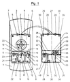
- the valve actuator housing shown in Figure 1 includes a base 1 pierced with a hole 2 in which appears an axis 3 of control intended to be attacked by a mandrel not shown thanks to which one can check the position of the shutter.
- Hole 2 is made in a first cell 4.
- This first cell 4 is of substantially rectangular shape.
- Sure one of the sides is provided with two fixing holes 5 intended for the passage of a screw, while noticeably at the tops of the cell, but slightly towards inside, two blind holes 6 are provided which communicate by grooves 7 with the edges of the cell also in the form of a groove.
- the base also includes a second cell 8, a third cell 9, a fourth cell 10 and a fifth cell 11. All of these cells having a substantially rectangular shape with a perimeter consisting of a throat.
- the face of the housing comprises, in the second cell 8, an orifice 12 passing through and an orifice 13 which communicates with an orifice 14 formed in the cell 10.
- the orifice 14 in turn communicates with an orifice 15 formed in the cell 10.
- the cell 9 has a orifice 16 passing through and an orifice 17 communicating with an orifice 19 of the cell 11.
- the orifice 19 communicates with an orifice 20 of the cell 11.
- a sixth cell 21 is provided, the perimeter of which is made up of a throat. This cell has two orifices 22 and 23.
- the orifice 22 communicates with the outside of the case, while the orifice 23 is through and communicates with the inside of the case.
- the seal which fits into the grooves forming the sides cells, in the form of a net delimiting several corresponding meshes to the alveoli.
- the substantially rectangular seal has two long sides 24, 25 and two short sides 26, 27.
- Side 27 has two circular parts 28 defining a hole for the passage of screws.
- two legs 29 lead to a stud 30 intended to penetrate the blind holes 6.
- the seal also has two bars 31, 32 parallel to side 26 and going from side 24 to side 25 and two bars 33, 34 parallel to side 24, the bar 33 going from side 26 to the bar 31, while bar 34 goes from side 26 to bar 32.
- the intersections of bars 33 and 34 with bar 32 have parts circular 28 for screw fixing.
- a stud 30 is also provided. From the bar 33 goes at an angle in the part corresponding to the cell 10, a bar 35 carrying a solid part 36. This solid part is not connected to the other sides of the joint part corresponding to the socket 10 so that it can lift or apply under the action of pressure.
- Another bar 37 perpendicular to the bar 35 connects the bar 31 to the circular part 28, but could also connect the strip 31 to the strip 33.
- a solid part 38 is connected by the bars 39, 40 to the side of the joint corresponding to the cell 11.
- a full part 41 is also provided in the part corresponding to the socket 21. This solid part 41 is connected to the bar 32 by a bar 42 and is also held by a bar 43, perpendicular to the bar 42.
- the solid parts 36, 38 and 41 apply respectively to holes 15, 20 and 23.
- the seal is made of an elastomeric material ensuring sealing, while the base of the housing is preferably metallic but can also be made of plastic.
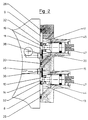
- the orifice 12 When you want to supply compressed air to the actuating cylinder tap, the orifice 12 is placed in communication with a source of compressed air. The compressed air passes into the cell 8 then into the orifice 13 and opens into chamber 44. As chamber 44 communicates with orifice 14, the passage is reduced by the needle 47, and with the orifice 15, the passage of which is closed by the solid part 36, which releases the orifice 15 under the effect of the pressure, the air preferably passes through the orifice 15 in the cell 10, which is connected by a conduit 46 to the jack.
Landscapes
- Engineering & Computer Science (AREA)
- General Engineering & Computer Science (AREA)
- Mechanical Engineering (AREA)
- Actuator (AREA)
- Fluid-Driven Valves (AREA)
- Infusion, Injection, And Reservoir Apparatuses (AREA)
- Gasket Seals (AREA)
- Lift Valve (AREA)
- Valve Housings (AREA)
Applications Claiming Priority (2)
| Application Number | Priority Date | Filing Date | Title |
|---|---|---|---|
| FR9615869A FR2757599B1 (fr) | 1996-12-23 | 1996-12-23 | Actionneur de robinet dans lequel la base du boitier est conformee de maniere a assurer les liaisons de distribution du fluide |
| FR9615869 | 1996-12-23 |
Publications (2)
| Publication Number | Publication Date |
|---|---|
| EP0851162A1 true EP0851162A1 (de) | 1998-07-01 |
| EP0851162B1 EP0851162B1 (de) | 2004-03-17 |
Family
ID=9499014
Family Applications (1)
| Application Number | Title | Priority Date | Filing Date |
|---|---|---|---|
| EP97402920A Expired - Lifetime EP0851162B1 (de) | 1996-12-23 | 1997-12-03 | Dichtung und Gehäuse, insbesondere für eine Antriebsvorrichtung für Ventile |
Country Status (6)
| Country | Link |
|---|---|
| US (1) | US6467753B1 (de) |
| EP (1) | EP0851162B1 (de) |
| JP (1) | JPH10184964A (de) |
| DE (1) | DE69728125T2 (de) |
| ES (1) | ES2216118T3 (de) |
| FR (1) | FR2757599B1 (de) |
Families Citing this family (1)
| Publication number | Priority date | Publication date | Assignee | Title |
|---|---|---|---|---|
| US6715320B2 (en) * | 2000-12-05 | 2004-04-06 | Vitro Corporativo, S.A. De C.V. | Fluid administration system for the operation of cylinder and piston assemblies |
Citations (3)
| Publication number | Priority date | Publication date | Assignee | Title |
|---|---|---|---|---|
| GB970776A (en) | 1961-12-05 | 1964-09-23 | Parker Hannifin Corp | Valve block |
| US4770210A (en) | 1987-07-23 | 1988-09-13 | Mac Valves, Inc. | Valve manifold stacking base |
| AT386878B (de) | 1985-12-13 | 1988-10-25 | Enfo Grundlagen Forschungs Ag | Deckelanordnung fuer ein wegeventil |
Family Cites Families (21)
| Publication number | Priority date | Publication date | Assignee | Title |
|---|---|---|---|---|
| US2558687A (en) * | 1948-06-22 | 1951-06-26 | Krueger Ernest Otto | Air speed control valve |
| US3025838A (en) * | 1958-11-17 | 1962-03-20 | Adolph V Klancnik | Machine tools |
| US3202060A (en) * | 1963-12-30 | 1965-08-24 | Pneumatic Hydraulic Dev Co Inc | Fluid power cylinder |
| DE2334413A1 (de) * | 1973-07-06 | 1975-01-30 | Wabco Westinghouse Gmbh | Pneumatischer stellantrieb |
| SE403395B (sv) * | 1975-09-19 | 1978-08-14 | Atlas Copco Ab | Uariabel pneumatisk strypventil |
| US4082108A (en) * | 1976-07-19 | 1978-04-04 | Maul Technology Corporation | Valve block |
| US4197874A (en) * | 1978-08-31 | 1980-04-15 | Mac Valves, Inc. | Pressure regulator and flow control valve with pre-exhaust vent means |
| US4241761A (en) * | 1979-01-09 | 1980-12-30 | Michael Ebert | Manifold valve assembly |
| US4253379A (en) * | 1979-10-01 | 1981-03-03 | American Standard Inc. | Fluid control system |
| US4381797A (en) * | 1981-02-09 | 1983-05-03 | Mac Valves, Inc. | Flow control valve with a non-rising stem |
| US4640309A (en) * | 1983-06-29 | 1987-02-03 | Parker Hannifin Corporation | Pilot operated poppet valve with speed control |
| DE4232628A1 (de) * | 1992-09-29 | 1994-03-31 | Herion Werke Kg | Wegeventil |
| DE69412911T2 (de) * | 1993-05-07 | 1999-05-12 | Smc K.K., Tokio/Tokyo | Wegeventil und Ventilanordnung für Wegeventile |
| EP0655575B2 (de) * | 1993-11-30 | 2007-03-28 | Smc Corporation | Servogesteuertes Mehrweg-Magnetventil |
| JP3486238B2 (ja) * | 1994-09-21 | 2004-01-13 | Smc株式会社 | 切換弁 |
| DE4443462A1 (de) * | 1994-12-07 | 1996-06-13 | Danfoss As | Zusatzeinrichtung für eine hydraulische Steuervorrichtung |
| JP3323349B2 (ja) * | 1994-12-27 | 2002-09-09 | エスエムシー株式会社 | 切換弁集合体 |
| JPH0932941A (ja) * | 1995-07-21 | 1997-02-07 | Smc Corp | 切換弁連設体 |
| CH692002A5 (de) * | 1995-08-22 | 2001-12-31 | Bosch Gmbh Robert | Hydraulikeinheit. |
| US5680883A (en) * | 1996-04-24 | 1997-10-28 | Eaton Corporation | Manifold and valve assembly and filter/gasket therefor |
| US5845672A (en) * | 1996-12-10 | 1998-12-08 | General Motors Corporation | Solenoid coil positioning assembly |
-
1996
- 1996-12-23 FR FR9615869A patent/FR2757599B1/fr not_active Expired - Fee Related
-
1997
- 1997-12-03 EP EP97402920A patent/EP0851162B1/de not_active Expired - Lifetime
- 1997-12-03 ES ES97402920T patent/ES2216118T3/es not_active Expired - Lifetime
- 1997-12-03 DE DE69728125T patent/DE69728125T2/de not_active Expired - Lifetime
- 1997-12-22 US US08/995,374 patent/US6467753B1/en not_active Expired - Fee Related
- 1997-12-24 JP JP9355410A patent/JPH10184964A/ja active Pending
Patent Citations (3)
| Publication number | Priority date | Publication date | Assignee | Title |
|---|---|---|---|---|
| GB970776A (en) | 1961-12-05 | 1964-09-23 | Parker Hannifin Corp | Valve block |
| AT386878B (de) | 1985-12-13 | 1988-10-25 | Enfo Grundlagen Forschungs Ag | Deckelanordnung fuer ein wegeventil |
| US4770210A (en) | 1987-07-23 | 1988-09-13 | Mac Valves, Inc. | Valve manifold stacking base |
Also Published As
| Publication number | Publication date |
|---|---|
| US6467753B1 (en) | 2002-10-22 |
| ES2216118T3 (es) | 2004-10-16 |
| FR2757599A1 (fr) | 1998-06-26 |
| FR2757599B1 (fr) | 1999-01-29 |
| DE69728125T2 (de) | 2004-08-26 |
| EP0851162B1 (de) | 2004-03-17 |
| DE69728125D1 (de) | 2004-04-22 |
| JPH10184964A (ja) | 1998-07-14 |
Similar Documents
| Publication | Publication Date | Title |
|---|---|---|
| EP0349377B1 (de) | Elektrisches Mikro-Umschaltventil mit einer einzigen Membran | |
| EP1299665B1 (de) | Pneumatisch angesteuertes ventil | |
| CA2175021A1 (en) | Needleless Connector | |
| ATE344900T1 (de) | Drehkraftreduziertes schieberventil mit wälzschraubtrieb | |
| EP1472462A4 (de) | Tellerventil mit verbessertem ventilsitz | |
| CA2421715A1 (en) | Self-sealing valve | |
| CA2170428A1 (en) | Ball Valve with a Strainer and Integrated Means for Flushing the Strainer | |
| ATE354723T1 (de) | In einem einlasskanal einer kolbenbrennkraftmaschine angeordnete zusatzsteuerventileinrichtung | |
| GB2315097A (en) | Push-pull valve assembly for an engine cylinder | |
| EP0851162B1 (de) | Dichtung und Gehäuse, insbesondere für eine Antriebsvorrichtung für Ventile | |
| ES2122830A1 (es) | Valvula rotatoria | |
| EP2588781A1 (de) | Flüssigkeitsventil | |
| FR2697888A1 (fr) | Vanne de régulation à bille ou à boisseau. | |
| CA2472525A1 (en) | Valve manifold assembly | |
| CR5730A (es) | Montaje de valvula de dos etapas para controlar eldesague de los servicios sanitarios | |
| FR2777229A1 (fr) | Clapet anti-retour pour reservoir de carburant | |
| FR2814734A1 (fr) | Reservoir d'eau amovible, notamment pour un four de cuisson a la vapeur | |
| FR2730293A1 (fr) | Clapet antiretour charge par un ressort, comportant un organe d'obturation pousse par un element a ressort contre un siege de clapet dans un corps de clapet | |
| FR2550602A1 (fr) | Electro-vanne | |
| CH655371A5 (fr) | Valve hydraulique. | |
| CA2430421A1 (en) | Refrigeration modulating valve sealing device | |
| FR2913414A1 (fr) | Tete de prehension d'articles par aspiration a deperdition d'aspiration controlee par un materiau deformable elastiquement. | |
| FR2660726A1 (fr) | Raccord - distributeur pour la commande d'actionneurs pneumatiques. | |
| FR2937394A1 (fr) | Vanne a volet rotatif | |
| FR2780105A3 (fr) | Compresseur |
Legal Events
| Date | Code | Title | Description |
|---|---|---|---|
| PUAI | Public reference made under article 153(3) epc to a published international application that has entered the european phase |
Free format text: ORIGINAL CODE: 0009012 |
|
| AK | Designated contracting states |
Kind code of ref document: A1 Designated state(s): DE ES FI FR GB IT NL |
|
| AX | Request for extension of the european patent |
Free format text: AL;LT;LV;MK;RO;SI |
|
| 17P | Request for examination filed |
Effective date: 19980611 |
|
| AKX | Designation fees paid |
Free format text: DE ES FI FR GB IT NL |
|
| RBV | Designated contracting states (corrected) |
Designated state(s): DE ES FI FR GB IT NL |
|
| RAP1 | Party data changed (applicant data changed or rights of an application transferred) |
Owner name: KSB S.A.S |
|
| GRAP | Despatch of communication of intention to grant a patent |
Free format text: ORIGINAL CODE: EPIDOSNIGR1 |
|
| GRAS | Grant fee paid |
Free format text: ORIGINAL CODE: EPIDOSNIGR3 |
|
| GRAA | (expected) grant |
Free format text: ORIGINAL CODE: 0009210 |
|
| AK | Designated contracting states |
Kind code of ref document: B1 Designated state(s): DE ES FI FR GB IT NL |
|
| REG | Reference to a national code |
Ref country code: GB Ref legal event code: FG4D Free format text: NOT ENGLISH |
|
| GBT | Gb: translation of ep patent filed (gb section 77(6)(a)/1977) |
Effective date: 20040317 |
|
| REF | Corresponds to: |
Ref document number: 69728125 Country of ref document: DE Date of ref document: 20040422 Kind code of ref document: P |
|
| REG | Reference to a national code |
Ref country code: ES Ref legal event code: FG2A Ref document number: 2216118 Country of ref document: ES Kind code of ref document: T3 |
|
| PLBE | No opposition filed within time limit |
Free format text: ORIGINAL CODE: 0009261 |
|
| STAA | Information on the status of an ep patent application or granted ep patent |
Free format text: STATUS: NO OPPOSITION FILED WITHIN TIME LIMIT |
|
| 26N | No opposition filed |
Effective date: 20041220 |
|
| PGFP | Annual fee paid to national office [announced via postgrant information from national office to epo] |
Ref country code: FI Payment date: 20091223 Year of fee payment: 13 Ref country code: ES Payment date: 20091209 Year of fee payment: 13 |
|
| PGFP | Annual fee paid to national office [announced via postgrant information from national office to epo] |
Ref country code: NL Payment date: 20091224 Year of fee payment: 13 |
|
| PGFP | Annual fee paid to national office [announced via postgrant information from national office to epo] |
Ref country code: IT Payment date: 20091217 Year of fee payment: 13 Ref country code: GB Payment date: 20091231 Year of fee payment: 13 Ref country code: FR Payment date: 20100106 Year of fee payment: 13 |
|
| PGFP | Annual fee paid to national office [announced via postgrant information from national office to epo] |
Ref country code: DE Payment date: 20091209 Year of fee payment: 13 |
|
| REG | Reference to a national code |
Ref country code: NL Ref legal event code: V1 Effective date: 20110701 |
|
| GBPC | Gb: european patent ceased through non-payment of renewal fee |
Effective date: 20101203 |
|
| PG25 | Lapsed in a contracting state [announced via postgrant information from national office to epo] |
Ref country code: FI Free format text: LAPSE BECAUSE OF NON-PAYMENT OF DUE FEES Effective date: 20101203 |
|
| REG | Reference to a national code |
Ref country code: FR Ref legal event code: ST Effective date: 20110831 |
|
| PG25 | Lapsed in a contracting state [announced via postgrant information from national office to epo] |
Ref country code: FR Free format text: LAPSE BECAUSE OF NON-PAYMENT OF DUE FEES Effective date: 20110103 |
|
| REG | Reference to a national code |
Ref country code: DE Ref legal event code: R119 Ref document number: 69728125 Country of ref document: DE Effective date: 20110701 |
|
| PG25 | Lapsed in a contracting state [announced via postgrant information from national office to epo] |
Ref country code: GB Free format text: LAPSE BECAUSE OF NON-PAYMENT OF DUE FEES Effective date: 20101203 Ref country code: DE Free format text: LAPSE BECAUSE OF NON-PAYMENT OF DUE FEES Effective date: 20110701 |
|
| PG25 | Lapsed in a contracting state [announced via postgrant information from national office to epo] |
Ref country code: IT Free format text: LAPSE BECAUSE OF NON-PAYMENT OF DUE FEES Effective date: 20101203 Ref country code: NL Free format text: LAPSE BECAUSE OF NON-PAYMENT OF DUE FEES Effective date: 20110701 |
|
| REG | Reference to a national code |
Ref country code: ES Ref legal event code: FD2A Effective date: 20120206 |
|
| PG25 | Lapsed in a contracting state [announced via postgrant information from national office to epo] |
Ref country code: ES Free format text: LAPSE BECAUSE OF NON-PAYMENT OF DUE FEES Effective date: 20101204 |