EP0851172A2 - Brûleur pour la mise en oeuvre d'une chambre de combustion avec un combustible liquide ou gazeux - Google Patents
Brûleur pour la mise en oeuvre d'une chambre de combustion avec un combustible liquide ou gazeux Download PDFInfo
- Publication number
- EP0851172A2 EP0851172A2 EP97810838A EP97810838A EP0851172A2 EP 0851172 A2 EP0851172 A2 EP 0851172A2 EP 97810838 A EP97810838 A EP 97810838A EP 97810838 A EP97810838 A EP 97810838A EP 0851172 A2 EP0851172 A2 EP 0851172A2
- Authority
- EP
- European Patent Office
- Prior art keywords
- burner
- flow
- zone
- air
- burner according
- Prior art date
- Legal status (The legal status is an assumption and is not a legal conclusion. Google has not performed a legal analysis and makes no representation as to the accuracy of the status listed.)
- Granted
Links
Images

Classifications
-
- F—MECHANICAL ENGINEERING; LIGHTING; HEATING; WEAPONS; BLASTING
- F23—COMBUSTION APPARATUS; COMBUSTION PROCESSES
- F23D—BURNERS
- F23D17/00—Burners for combustion simultaneously or alternately of gaseous or liquid or pulverulent fuel
- F23D17/002—Burners for combustion simultaneously or alternately of gaseous or liquid or pulverulent fuel gaseous or liquid fuel
-
- F—MECHANICAL ENGINEERING; LIGHTING; HEATING; WEAPONS; BLASTING
- F23—COMBUSTION APPARATUS; COMBUSTION PROCESSES
- F23C—METHODS OR APPARATUS FOR COMBUSTION USING FLUID FUEL OR SOLID FUEL SUSPENDED IN A CARRIER GAS OR AIR
- F23C7/00—Combustion apparatus characterised by arrangements for air supply
- F23C7/002—Combustion apparatus characterised by arrangements for air supply the air being submitted to a rotary or spinning motion
-
- F—MECHANICAL ENGINEERING; LIGHTING; HEATING; WEAPONS; BLASTING
- F23—COMBUSTION APPARATUS; COMBUSTION PROCESSES
- F23C—METHODS OR APPARATUS FOR COMBUSTION USING FLUID FUEL OR SOLID FUEL SUSPENDED IN A CARRIER GAS OR AIR
- F23C2900/00—Special features of, or arrangements for combustion apparatus using fluid fuels or solid fuels suspended in air; Combustion processes therefor
- F23C2900/07002—Premix burners with air inlet slots obtained between offset curved wall surfaces, e.g. double cone burners
-
- F—MECHANICAL ENGINEERING; LIGHTING; HEATING; WEAPONS; BLASTING
- F23—COMBUSTION APPARATUS; COMBUSTION PROCESSES
- F23D—BURNERS
- F23D2209/00—Safety arrangements
- F23D2209/10—Flame flashback
Definitions
- the present invention relates to a burner according to the preamble of claim 1.
- Step on the outer boundary of the swirl flow field particularly low speeds because at constant Total pressure in the arrangement of the static pressure from the inside to the outside, causing the dynamic pressure caused by the absolute speed is represented with increasing Radius is getting smaller. These low speeds may no longer be able to prevent the flame from the combustion chamber, along the boundary layer, into the burner reproduces and can then overheat and destroy it.
- the invention seeks to remedy this.
- the invention how it is characterized in the claims, the task lies based on precautions for a burner of the type mentioned to meet those who are capable of a flashback to prevent safely.
- the main advantage of the invention is that that this additional device of the simplest design is, and be installed as required in the burner mentioned can intervene without changing the basic concept of the same to have, with which such a burner, which is at medium compressor pressure ratios already well proven has, also for the further development stages of Gas turbines can be taken over and used.
- additional air is injected along made of the burner walls, preferably in the downstream half of the burner.
- This additional air forms a film along the wall and mixes it then slowly with the fuel-enriched main flow.
- the essential improvement in security against one Backfire is based on two principles.
- the mixture is diluted with weight. There the burner is operating near its lean extinguishing limit weak local dilution of the mixture results along the walls to the desired loss of flammability of the mixture along the walls.
- this additional air is injected so that the axial speed is increased along the wall, which is also convenient affects the operation of such a burner.
- the pulse density ratio between film air and main flow in the range of 1 since both flows are common be accelerated from the same total pressure. Other impulses are also easily conceivable, they have striven for Effect no negative effects.
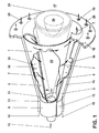
- Fig. 1 shows a burner in perspective.
- Fig. 2 For a better understanding of the subject, it is advantageous if at the same time when studying Fig. 1 based on the description Fig. 2 is also used.
- Partial bodies 1, 2 which are nested offset from one another are.
- the offset of the respective central axis or Longitudinal axis of symmetry of the partial bodies 1, 2 to one another creates on both sides, in mirror image Arrangement, each having a tangential air inlet duct 5, 6 free, through which the combustion air 7 in the interior of the Brenner, i.e.
- the two tapered Partial bodies 1, 2 each have a cylindrical initial part 9, 10, which also, analogously to the aforementioned partial bodies 1, 2, offset to each other, so that the tangential Air inlet channels 5, 6 over the entire length of the Brenners are present.
- a nozzle 11 for preferably atomizing a liquid fuel 12 housed such that their injection approximately with the narrowest cross section of the the partial body 1, 2 formed conical cavity 8 coincides.
- the injection capacity and the operating mode of this Nozzle 11 depends on the given parameters of the respective Brenners.
- the fuel injected through the nozzle 11 12 can be enriched with a recirculated exhaust gas if necessary will; then it is also possible to pass through the nozzle 11 to provide the complementary injection of a quantity of water.
- the burner can be purely conical, that is, without cylindrical starting parts 9, 10 may be formed.
- the partial body 1, 2 each have a fuel line 13, 14, which along the tangential inlet channels 5, 6 arranged and provided with injection openings 15, through which preferably a gaseous fuel 16 in the combustion air 7 flowing there is injected, as this is symbolized by arrows 16, these Injection at the same time the fuel injection level (see Fig. 3, item 22) of the system.
- These fuel lines 13, 14 are preferably at the latest at the end of the tangential inflow, before entering the cone cavity 8, placed this to ensure an optimal air / fuel mixture.
- the burner On the combustion chamber side, the burner has an anchor for the partial body 1, 2 serving front panel 18 with a number Bores 19 through which a mixing or Cooling air 20 or the front part of the combustion chamber 17 Wall is fed.
- Liquid fuel 12 is used to operate the burner the central nozzle 11 is used, this is under one acute angle in the cone cavity 8 or in the combustion chamber 17 injected. A nozzle is thus formed from the nozzle 11 Fuel profile 23, which flows in from the tangential rotating combustion air 7 is enclosed. In axial Direction is the concentration of the injected fuel 12 continuously through the incoming combustion air 7 an optimal mixture degraded. If the burner with a operated gaseous fuel 16, this can in principle also happen via the fuel nozzle 11, preferably but this happens via the injection openings 15, whereby the formation of this fuel / air mixture right at the end the air inlet channels 5, 6 comes about.
- a backflow zone also forms there or backflow bladder 24 (vortex breakdown) with one opposite the flame front 25 acting there stabilizing Effect one, in the sense that the backflow zone 24 has the function of a disembodied flame holder.
- the optimal fuel concentration across the cross-section is only in the area of vertebral bursting, i.e. in the area the backflow zone 24 reached. Only at this point then a stable flame front 25.
- the flame stabilizing Effect results from that in the cone cavity 8 forming swirl number in the direction of flow along the cone axis. The flame strikes back inside the burner therefore occurs due to this fluidic specification not on.
- the flow opening is minimized of the tangential air inlet ducts 6, 7 is predestined is the backflow zone 24 from the end of the premixing section to build.
- the construction of the burner is suitable furthermore excellent, the flow opening of the tangential To change air inlet channels 5, 6 as required, with what a relative without changing the overall length of the burner large operational bandwidth can be captured.
- the partial body 1, 2 in another Plane can be shifted towards each other, which even overlaps opposite the air inlet plane into the cone cavity 8 (See FIG. 2, item 21) of the same in the area of the tangential Air inlet channels 5, 6, as shown in Fig. 2, accomplished can be. It is then also possible that Partial body 1, 2 by a counter-rotating movement to nest in a spiral.
- Fig. 2 shows the same burner according to Fig. 1 but from a different one Perspective and in a simplified form.
- This figure 2 mainly wants the disposition of the two conical ones Show part body 1, 2 and their offset to each other.
- the Displacement of the respective central axis 3, 4 of the two partial bodies to each other, based on the main central axis 26 of the Burner, which is the main axis of the central fuel nozzle 11 corresponds to the respective size of the flow openings the tangential air inlet ducts 5, 6.
- the central axes 3, 4 run parallel to each other here.
- Zone 27 in which the placements of Means for the injection of additional air takes place.
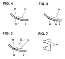
- FIGS. 4 and 5 show a development 28 of a conical partial body, which schematically shows zone 27 within which has a specific configuration of injection openings for additional air, which ensure a reignition lock, is taken as a basis.
- the orientation of the injection openings 29 as well as their number and size will be the respective Flow conditions in the burner adjusted.
- the final Purpose is primarily aimed at the reignition barrier.
- the individual oblique lines 30 want the placement of the symbolize individual rows of the injection openings 29.
- the arrows 31 point to the outflow direction of the Additional air indicate that is at right angles to the Level 30 of the injection openings 29 runs. This outflow direction can, however, range from purely axial to direction the main flow vary. For better understanding are in this processing 28 a single row and one Double row of injection openings 29 shown. The corresponding cuts are then shown in FIGS. 4 and 5.
- Fig. 4 shows the design of a simple row of injection openings 29.
- the additional air 32 is here under one injected acute angle with respect to the swirl flow 7a flat to the inner wall of the corresponding partial body 2, this around improve film production.
- FIG. 5 shows a double row of injection openings 29. Basically, the same precautions are taken here as described in Fig. 3.
- the injection openings 33 run in the area the inner wall of the corresponding partial body 2 fan-shaped, as shown in Fig. 7, which is a plan view.
Landscapes
- Engineering & Computer Science (AREA)
- Chemical & Material Sciences (AREA)
- Combustion & Propulsion (AREA)
- Mechanical Engineering (AREA)
- General Engineering & Computer Science (AREA)
- Gas Burners (AREA)
- Pre-Mixing And Non-Premixing Gas Burner (AREA)
Applications Claiming Priority (2)
| Application Number | Priority Date | Filing Date | Title |
|---|---|---|---|
| DE19654116 | 1996-12-23 | ||
| DE19654116A DE19654116A1 (de) | 1996-12-23 | 1996-12-23 | Brenner zum Betrieb einer Brennkammer mit einem flüssigen und/oder gasförmigen Brennstoff |
Publications (3)
| Publication Number | Publication Date |
|---|---|
| EP0851172A2 true EP0851172A2 (fr) | 1998-07-01 |
| EP0851172A3 EP0851172A3 (fr) | 1999-06-09 |
| EP0851172B1 EP0851172B1 (fr) | 2003-07-16 |
Family
ID=7816084
Family Applications (1)
| Application Number | Title | Priority Date | Filing Date |
|---|---|---|---|
| EP97810838A Expired - Lifetime EP0851172B1 (fr) | 1996-12-23 | 1997-11-07 | Brûleur et méthode pour la mise en oeuvre d'une chambre de combustion avec un combustible liquide et/ou gazeux |
Country Status (3)
| Country | Link |
|---|---|
| US (1) | US5921770A (fr) |
| EP (1) | EP0851172B1 (fr) |
| DE (2) | DE19654116A1 (fr) |
Cited By (10)
| Publication number | Priority date | Publication date | Assignee | Title |
|---|---|---|---|---|
| EP0959298A3 (fr) * | 1998-05-18 | 2000-02-23 | United Technologies Corporation | Injecteur de combustible à prémélange et son procédé de mise en oeuvre |
| EP1001214B1 (fr) * | 1998-11-09 | 2004-09-15 | ALSTOM Technology Ltd | Brûleur |
| EP1002992B1 (fr) * | 1998-11-18 | 2004-09-29 | ALSTOM Technology Ltd | Brûleur |
| EP0987491B1 (fr) * | 1998-09-16 | 2005-07-20 | ALSTOM Technology Ltd | Procédé pour prévenir les instabilités d'écoulement dans un brûleur |
| CH703655A1 (de) * | 2010-08-27 | 2012-02-29 | Alstom Technology Ltd | Vormischbrenner für eine gasturbine. |
| EP2685162A1 (fr) | 2012-07-10 | 2014-01-15 | Alstom Technology Ltd | Brûleur de prémélange du type multi-cônes destiné à une turbine à gaz et procédé de fonctionnement d'un tel brûleur |
| EP2685163A1 (fr) | 2012-07-10 | 2014-01-15 | Alstom Technology Ltd | Brûleur de prémélange du type multi-cônes destiné à une turbine à gaz |
| EP2685161A1 (fr) | 2012-07-10 | 2014-01-15 | Alstom Technology Ltd | Agencement de chambre de combustion, en particulier pour turbine à gaz |
| EP2685160A1 (fr) | 2012-07-10 | 2014-01-15 | Alstom Technology Ltd | Brûleur de prémélange du type multi-cônes destiné à une turbine à gaz |
| EP3299720A1 (fr) | 2016-09-22 | 2018-03-28 | Ansaldo Energia IP UK Limited | Ensemble avant de chambre de combustion pour turbine à gaz |
Families Citing this family (9)
| Publication number | Priority date | Publication date | Assignee | Title |
|---|---|---|---|---|
| RU2168460C2 (ru) * | 1999-07-14 | 2001-06-10 | Кубиков Валентин Борисович | Коаксиальный смесительный элемент-горелка типа "газ-газ" для камер сгорания высокопроизводительных генераторов синтез-газа |
| DE10051221A1 (de) * | 2000-10-16 | 2002-07-11 | Alstom Switzerland Ltd | Brenner mit gestufter Brennstoff-Eindüsung |
| EP1817526B1 (fr) * | 2004-11-30 | 2019-03-20 | Ansaldo Energia Switzerland AG | Procédé et dispositif de combustion d'hydrogène dans un brûleur a prémelange |
| EP2257736B1 (fr) | 2008-03-07 | 2015-11-25 | Alstom Technology Ltd | Procédé de production de gaz chaud |
| JP5453322B2 (ja) | 2008-03-07 | 2014-03-26 | アルストム テクノロジー リミテッド | バーナ装置並びにバーナ装置の使用 |
| GB2512894A (en) * | 2013-04-10 | 2014-10-15 | David Thomas Bell | Inward firing multiple zoned gas burner |
| KR101990767B1 (ko) | 2017-08-09 | 2019-06-20 | 한국기계연구원 | 이중 원추형 가스터빈용 버너 및 이 버너에 공기를 공급하는 방법 |
| DE102018005192B3 (de) | 2018-07-02 | 2019-12-05 | Truma Gerätetechnik GmbH & Co. KG | Brennervorrichtung |
| US11852319B2 (en) * | 2021-02-26 | 2023-12-26 | Armando Parra | Control means for vortex flame device |
Citations (2)
| Publication number | Priority date | Publication date | Assignee | Title |
|---|---|---|---|---|
| EP0321809B1 (fr) | 1987-12-21 | 1991-05-15 | BBC Brown Boveri AG | Procédé pour la combustion de combustible liquide dans un brûleur |
| EP0704657A2 (fr) | 1994-10-01 | 1996-04-03 | ABB Management AG | Brûleur |
Family Cites Families (10)
| Publication number | Priority date | Publication date | Assignee | Title |
|---|---|---|---|---|
| FR758974A (fr) * | 1933-07-28 | 1934-01-26 | Indugas Ind U Gasofen Bauges M | Brûleur à gaz à longueur de flamme réglable |
| US2665748A (en) * | 1949-05-27 | 1954-01-12 | Frank H Cornelius | Fuel burner |
| US3951584A (en) * | 1974-05-23 | 1976-04-20 | Midland-Ross Corporation | Self-stabilizing burner |
| US3975141A (en) * | 1974-06-25 | 1976-08-17 | The United States Of America As Represented By The Secretary Of The Army | Combustion liner swirler |
| US3958416A (en) * | 1974-12-12 | 1976-05-25 | General Motors Corporation | Combustion apparatus |
| CH680157A5 (fr) * | 1989-12-01 | 1992-06-30 | Asea Brown Boveri | |
| DE4330083A1 (de) * | 1993-09-06 | 1995-03-09 | Abb Research Ltd | Verfahren zum Betrieb eines Vormischbrenners |
| DE4409918A1 (de) * | 1994-03-23 | 1995-09-28 | Abb Management Ag | Brenner zum Betrieb einer Brennkammer |
| DE19545036A1 (de) * | 1995-12-02 | 1997-06-05 | Abb Research Ltd | Vormischbrenner |
| DE19545310B4 (de) * | 1995-12-05 | 2008-06-26 | Alstom | Vormischbrenner |
-
1996
- 1996-12-23 DE DE19654116A patent/DE19654116A1/de not_active Withdrawn
-
1997
- 1997-11-07 EP EP97810838A patent/EP0851172B1/fr not_active Expired - Lifetime
- 1997-11-07 DE DE59710441T patent/DE59710441D1/de not_active Expired - Lifetime
- 1997-11-20 US US08/975,301 patent/US5921770A/en not_active Expired - Fee Related
Patent Citations (2)
| Publication number | Priority date | Publication date | Assignee | Title |
|---|---|---|---|---|
| EP0321809B1 (fr) | 1987-12-21 | 1991-05-15 | BBC Brown Boveri AG | Procédé pour la combustion de combustible liquide dans un brûleur |
| EP0704657A2 (fr) | 1994-10-01 | 1996-04-03 | ABB Management AG | Brûleur |
Cited By (19)
| Publication number | Priority date | Publication date | Assignee | Title |
|---|---|---|---|---|
| EP0959298A3 (fr) * | 1998-05-18 | 2000-02-23 | United Technologies Corporation | Injecteur de combustible à prémélange et son procédé de mise en oeuvre |
| EP0987491B1 (fr) * | 1998-09-16 | 2005-07-20 | ALSTOM Technology Ltd | Procédé pour prévenir les instabilités d'écoulement dans un brûleur |
| EP1001214B1 (fr) * | 1998-11-09 | 2004-09-15 | ALSTOM Technology Ltd | Brûleur |
| EP1002992B1 (fr) * | 1998-11-18 | 2004-09-29 | ALSTOM Technology Ltd | Brûleur |
| CH703655A1 (de) * | 2010-08-27 | 2012-02-29 | Alstom Technology Ltd | Vormischbrenner für eine gasturbine. |
| EP2423597A2 (fr) | 2010-08-27 | 2012-02-29 | Alstom Technology Ltd | Brûleur à prémélange pour une turbine à gaz |
| EP2423597A3 (fr) * | 2010-08-27 | 2012-08-15 | Alstom Technology Ltd | Brûleur à prémélange pour une turbine à gaz |
| US9170022B2 (en) | 2010-08-27 | 2015-10-27 | Alstom Technology Ltd | Premix burner for a gas turbine |
| EP2685163A1 (fr) | 2012-07-10 | 2014-01-15 | Alstom Technology Ltd | Brûleur de prémélange du type multi-cônes destiné à une turbine à gaz |
| EP2685161A1 (fr) | 2012-07-10 | 2014-01-15 | Alstom Technology Ltd | Agencement de chambre de combustion, en particulier pour turbine à gaz |
| EP2685160A1 (fr) | 2012-07-10 | 2014-01-15 | Alstom Technology Ltd | Brûleur de prémélange du type multi-cônes destiné à une turbine à gaz |
| US8950187B2 (en) | 2012-07-10 | 2015-02-10 | Alstom Technology Ltd | Premix burner of the multi-cone type for a gas turbine |
| RU2551706C2 (ru) * | 2012-07-10 | 2015-05-27 | Альстом Текнолоджи Лтд | Горелка предварительного смешивания многоконусного типа для газовой турбины |
| RU2561767C2 (ru) * | 2012-07-10 | 2015-09-10 | Альстом Текнолоджи Лтд | Горелка многоконусного типа предварительного смешивания для газовой турбины |
| EP2685162A1 (fr) | 2012-07-10 | 2014-01-15 | Alstom Technology Ltd | Brûleur de prémélange du type multi-cônes destiné à une turbine à gaz et procédé de fonctionnement d'un tel brûleur |
| RU2573090C2 (ru) * | 2012-07-10 | 2016-01-20 | Альстом Текнолоджи Лтд. | Узел камеры сгорания, в частности для газовой турбины |
| US9441837B2 (en) | 2012-07-10 | 2016-09-13 | General Electric Technology Gmbh | Premix burner of the multi-cone type for a gas turbine |
| US9933163B2 (en) | 2012-07-10 | 2018-04-03 | Ansaldo Energia Switzerland AG | Combustor arrangement with slidable multi-cone premix burner |
| EP3299720A1 (fr) | 2016-09-22 | 2018-03-28 | Ansaldo Energia IP UK Limited | Ensemble avant de chambre de combustion pour turbine à gaz |
Also Published As
| Publication number | Publication date |
|---|---|
| DE59710441D1 (de) | 2003-08-21 |
| US5921770A (en) | 1999-07-13 |
| EP0851172A3 (fr) | 1999-06-09 |
| DE19654116A1 (de) | 1998-06-25 |
| EP0851172B1 (fr) | 2003-07-16 |
Similar Documents
| Publication | Publication Date | Title |
|---|---|---|
| EP0851172B1 (fr) | Brûleur et méthode pour la mise en oeuvre d'une chambre de combustion avec un combustible liquide et/ou gazeux | |
| DE4426351B4 (de) | Brennkammer für eine Gasturbine | |
| EP0704657B1 (fr) | Brûleur | |
| EP0387532B1 (fr) | Chambre de combustion d'une turbine à gaz | |
| EP0401529B1 (fr) | Chambre de combustion d'une turbine à gaz | |
| EP0718561B1 (fr) | Brûleur | |
| EP0777081B1 (fr) | Brûleur à prémélange | |
| EP0481111B1 (fr) | Chambre de combustion pour turbine à gaz | |
| EP0918190A1 (fr) | Brûleur pour la mise en oeuvre d'un générateur de chaleur | |
| DE19757189B4 (de) | Verfahren zum Betrieb eines Brenners eines Wärmeerzeugers | |
| EP0780630A2 (fr) | Brûleur pour un générateur de chaleur | |
| EP0521325B1 (fr) | Chambre de combustion | |
| EP0775869A2 (fr) | Brûleur à prémélange | |
| EP0994300B1 (fr) | Brûleur pour la conduite d'un générateur de chaleur | |
| EP0909921B1 (fr) | Brûleur pour la mise en oeuvre d'un générateur de chaleur | |
| EP0931980A1 (fr) | Brûleur pour la mise en oeuvre d'un générateur de chaleur | |
| EP0483554B1 (fr) | Procédé pour la réduction au minimum des émissions de NOx dans une combustion | |
| EP0751351A1 (fr) | Chambre de combustion | |
| EP0740108A2 (fr) | Brûleur | |
| EP0833104B1 (fr) | Brûleur pour le fonctionnement d'une chambre de combustion | |
| DE19537636B4 (de) | Kraftwerksanlage | |
| EP0913630B1 (fr) | Brûleur pour la mise en oeuvre d'un générateur de chaleur | |
| EP0730121A2 (fr) | Brûleur à prémélange | |
| EP0780628B1 (fr) | Brûleur à prémélange pour un générateur de chaleur | |
| EP0786626A1 (fr) | Brûleur à prémélange |
Legal Events
| Date | Code | Title | Description |
|---|---|---|---|
| PUAI | Public reference made under article 153(3) epc to a published international application that has entered the european phase |
Free format text: ORIGINAL CODE: 0009012 |
|
| AK | Designated contracting states |
Kind code of ref document: A2 Designated state(s): CH DE FR GB LI |
|
| AX | Request for extension of the european patent |
Free format text: AL;LT;LV;MK;RO;SI |
|
| PUAL | Search report despatched |
Free format text: ORIGINAL CODE: 0009013 |
|
| AK | Designated contracting states |
Kind code of ref document: A3 Designated state(s): AT BE CH DE DK ES FI FR GB GR IE IT LI LU MC NL PT SE |
|
| AX | Request for extension of the european patent |
Free format text: AL;LT;LV;MK;RO;SI |
|
| 17P | Request for examination filed |
Effective date: 19991011 |
|
| AKX | Designation fees paid |
Free format text: CH DE FR GB LI |
|
| 17Q | First examination report despatched |
Effective date: 20010914 |
|
| RAP1 | Party data changed (applicant data changed or rights of an application transferred) |
Owner name: ALSTOM |
|
| RTI1 | Title (correction) |
Free format text: BURNER AND METHOD FOR OPERATING A COMBUSTION CHAMBER WITH A LIQUID AND/OR GASEOUS FUEL |
|
| GRAH | Despatch of communication of intention to grant a patent |
Free format text: ORIGINAL CODE: EPIDOS IGRA |
|
| RAP1 | Party data changed (applicant data changed or rights of an application transferred) |
Owner name: ALSTOM (SWITZERLAND) LTD |
|
| GRAH | Despatch of communication of intention to grant a patent |
Free format text: ORIGINAL CODE: EPIDOS IGRA |
|
| GRAA | (expected) grant |
Free format text: ORIGINAL CODE: 0009210 |
|
| AK | Designated contracting states |
Designated state(s): CH DE FR GB LI |
|
| PG25 | Lapsed in a contracting state [announced via postgrant information from national office to epo] |
Ref country code: FR Free format text: LAPSE BECAUSE OF FAILURE TO SUBMIT A TRANSLATION OF THE DESCRIPTION OR TO PAY THE FEE WITHIN THE PRESCRIBED TIME-LIMIT Effective date: 20030716 |
|
| REG | Reference to a national code |
Ref country code: GB Ref legal event code: FG4D Free format text: NOT ENGLISH |
|
| REG | Reference to a national code |
Ref country code: CH Ref legal event code: EP |
|
| REF | Corresponds to: |
Ref document number: 59710441 Country of ref document: DE Date of ref document: 20030821 Kind code of ref document: P |
|
| GBT | Gb: translation of ep patent filed (gb section 77(6)(a)/1977) |
Effective date: 20031015 |
|
| PG25 | Lapsed in a contracting state [announced via postgrant information from national office to epo] |
Ref country code: LI Free format text: LAPSE BECAUSE OF NON-PAYMENT OF DUE FEES Effective date: 20031130 Ref country code: CH Free format text: LAPSE BECAUSE OF NON-PAYMENT OF DUE FEES Effective date: 20031130 |
|
| PLBE | No opposition filed within time limit |
Free format text: ORIGINAL CODE: 0009261 |
|
| STAA | Information on the status of an ep patent application or granted ep patent |
Free format text: STATUS: NO OPPOSITION FILED WITHIN TIME LIMIT |
|
| 26N | No opposition filed |
Effective date: 20040419 |
|
| REG | Reference to a national code |
Ref country code: CH Ref legal event code: PL |
|
| EN | Fr: translation not filed | ||
| PGFP | Annual fee paid to national office [announced via postgrant information from national office to epo] |
Ref country code: DE Payment date: 20091130 Year of fee payment: 13 |
|
| PGFP | Annual fee paid to national office [announced via postgrant information from national office to epo] |
Ref country code: GB Payment date: 20091007 Year of fee payment: 13 |
|
| GBPC | Gb: european patent ceased through non-payment of renewal fee |
Effective date: 20101107 |
|
| REG | Reference to a national code |
Ref country code: DE Ref legal event code: R119 Ref document number: 59710441 Country of ref document: DE Effective date: 20110601 Ref country code: DE Ref legal event code: R119 Ref document number: 59710441 Country of ref document: DE Effective date: 20110531 |
|
| PG25 | Lapsed in a contracting state [announced via postgrant information from national office to epo] |
Ref country code: DE Free format text: LAPSE BECAUSE OF NON-PAYMENT OF DUE FEES Effective date: 20110531 |
|
| PG25 | Lapsed in a contracting state [announced via postgrant information from national office to epo] |
Ref country code: GB Free format text: LAPSE BECAUSE OF NON-PAYMENT OF DUE FEES Effective date: 20101107 |