EP0851180B1 - Installation de chauffage - Google Patents
Installation de chauffage Download PDFInfo
- Publication number
- EP0851180B1 EP0851180B1 EP97113483A EP97113483A EP0851180B1 EP 0851180 B1 EP0851180 B1 EP 0851180B1 EP 97113483 A EP97113483 A EP 97113483A EP 97113483 A EP97113483 A EP 97113483A EP 0851180 B1 EP0851180 B1 EP 0851180B1
- Authority
- EP
- European Patent Office
- Prior art keywords
- combustion chamber
- wall
- heating system
- heat exchanger
- tank
- Prior art date
- Legal status (The legal status is an assumption and is not a legal conclusion. Google has not performed a legal analysis and makes no representation as to the accuracy of the status listed.)
- Expired - Lifetime
Links
- 238000010438 heat treatment Methods 0.000 title claims description 33
- 238000009434 installation Methods 0.000 title 1
- XLYOFNOQVPJJNP-UHFFFAOYSA-N water Substances O XLYOFNOQVPJJNP-UHFFFAOYSA-N 0.000 claims abstract description 32
- 238000002485 combustion reaction Methods 0.000 claims description 75
- 239000013505 freshwater Substances 0.000 claims description 5
- 238000005338 heat storage Methods 0.000 claims description 5
- 239000000446 fuel Substances 0.000 claims description 3
- 239000003546 flue gas Substances 0.000 description 7
- 238000009833 condensation Methods 0.000 description 6
- 230000005494 condensation Effects 0.000 description 6
- UGFAIRIUMAVXCW-UHFFFAOYSA-N Carbon monoxide Chemical compound [O+]#[C-] UGFAIRIUMAVXCW-UHFFFAOYSA-N 0.000 description 5
- 230000015572 biosynthetic process Effects 0.000 description 2
- 230000007797 corrosion Effects 0.000 description 2
- 238000005260 corrosion Methods 0.000 description 2
- 239000002737 fuel gas Substances 0.000 description 2
- 238000013021 overheating Methods 0.000 description 2
- NINIDFKCEFEMDL-UHFFFAOYSA-N Sulfur Chemical compound [S] NINIDFKCEFEMDL-UHFFFAOYSA-N 0.000 description 1
- 239000002253 acid Substances 0.000 description 1
- 239000003651 drinking water Substances 0.000 description 1
- 235000020188 drinking water Nutrition 0.000 description 1
- 230000002349 favourable effect Effects 0.000 description 1
- 239000003517 fume Substances 0.000 description 1
- 239000007789 gas Substances 0.000 description 1
- 239000002184 metal Substances 0.000 description 1
- 238000002360 preparation method Methods 0.000 description 1
- 238000013517 stratification Methods 0.000 description 1
- 229910052717 sulfur Inorganic materials 0.000 description 1
- 239000011593 sulfur Substances 0.000 description 1
Images

Classifications
-
- F—MECHANICAL ENGINEERING; LIGHTING; HEATING; WEAPONS; BLASTING
- F24—HEATING; RANGES; VENTILATING
- F24H—FLUID HEATERS, e.g. WATER OR AIR HEATERS, HAVING HEAT-GENERATING MEANS, e.g. HEAT PUMPS, IN GENERAL
- F24H1/00—Water heaters, e.g. boilers, continuous-flow heaters or water-storage heaters
- F24H1/48—Water heaters for central heating incorporating heaters for domestic water
- F24H1/52—Water heaters for central heating incorporating heaters for domestic water incorporating heat exchangers for domestic water
-
- F—MECHANICAL ENGINEERING; LIGHTING; HEATING; WEAPONS; BLASTING
- F24—HEATING; RANGES; VENTILATING
- F24H—FLUID HEATERS, e.g. WATER OR AIR HEATERS, HAVING HEAT-GENERATING MEANS, e.g. HEAT PUMPS, IN GENERAL
- F24H1/00—Water heaters, e.g. boilers, continuous-flow heaters or water-storage heaters
- F24H1/22—Water heaters other than continuous-flow or water-storage heaters, e.g. water heaters for central heating
- F24H1/24—Water heaters other than continuous-flow or water-storage heaters, e.g. water heaters for central heating with water mantle surrounding the combustion chamber or chambers
- F24H1/26—Water heaters other than continuous-flow or water-storage heaters, e.g. water heaters for central heating with water mantle surrounding the combustion chamber or chambers the water mantle forming an integral body
- F24H1/28—Water heaters other than continuous-flow or water-storage heaters, e.g. water heaters for central heating with water mantle surrounding the combustion chamber or chambers the water mantle forming an integral body including one or more furnace or fire tubes
-
- F—MECHANICAL ENGINEERING; LIGHTING; HEATING; WEAPONS; BLASTING
- F24—HEATING; RANGES; VENTILATING
- F24H—FLUID HEATERS, e.g. WATER OR AIR HEATERS, HAVING HEAT-GENERATING MEANS, e.g. HEAT PUMPS, IN GENERAL
- F24H9/00—Details
- F24H9/0005—Details for water heaters
- F24H9/0036—Dispositions against condensation of combustion products
-
- F—MECHANICAL ENGINEERING; LIGHTING; HEATING; WEAPONS; BLASTING
- F24—HEATING; RANGES; VENTILATING
- F24H—FLUID HEATERS, e.g. WATER OR AIR HEATERS, HAVING HEAT-GENERATING MEANS, e.g. HEAT PUMPS, IN GENERAL
- F24H7/00—Storage heaters, i.e. heaters in which the energy is stored as heat in masses for subsequent release
- F24H7/02—Storage heaters, i.e. heaters in which the energy is stored as heat in masses for subsequent release the released heat being conveyed to a transfer fluid
- F24H7/04—Storage heaters, i.e. heaters in which the energy is stored as heat in masses for subsequent release the released heat being conveyed to a transfer fluid with forced circulation of the transfer fluid
- F24H7/045—Storage heaters, i.e. heaters in which the energy is stored as heat in masses for subsequent release the released heat being conveyed to a transfer fluid with forced circulation of the transfer fluid using fluid fuel
- F24H7/0466—Storage heaters, i.e. heaters in which the energy is stored as heat in masses for subsequent release the released heat being conveyed to a transfer fluid with forced circulation of the transfer fluid using fluid fuel the transfer fluid being water
Definitions
- the present invention relates to a heating system with a Heat storage serving, filled with water as a heat storage medium Container and a combustion chamber present in the container circular cross-section for heating the storage water Combustion of a fuel, the combustion chamber at least on their underside at a short distance from a partially circular in cross section Wall is surrounded and between the combustion chamber and wall-formed space is open to the container.
- Such heating systems are known in many ways.
- the use The heat stored in the water can take place in that the water via supply and return lines in the circuit to heating surfaces, such as radiators and underfloor heating, where there is heat emits.
- Another one, especially for heating fresh water is in the tank with the storage water to arrange a heat exchanger through which to be heated Drinking water is led. Combinations of both variants are known.
- heat loss is caused by heating the combustion chamber balanced by a fuel in the combustion chamber, for example Oil or gas being burned.
- the heat generated is transferred from the combustion chamber to the storage water surrounding the combustion chamber.
- a problem here is that in the fuel gas and / or the The resulting flue gas water vapor on the inner walls the combustion chamber condenses. This condensation water brings together with the sulfur contained in the fuel or flue gases Acid formation and thus corrosion of the combustion chamber walls.
- This problem can be reduced by having the combustion chamber at least partially surrounded by a wall at a short distance is, the space formed between the combustion chamber and the wall the container is open.
- Such a heating system is known from FR 2 629 907. at this heating system is a wall surrounding the combustion chamber available on both sides of the combustion chamber only to below half the height of the combustion chamber is sufficient. The is accordingly low water circulation caused by this wall. It is therefore done only a little exchange of water in the space between the walls and combustion chamber with the water outside in the container.
- DE 34 12 331 C 1 shows a heating system, but not the Combustion chamber surrounding wall of the type mentioned.
- the invention has for its object a heating system of the beginning to improve the type mentioned.
- the effectiveness of the wall surrounding the combustion chamber can be improved.
- the height of the combustion chamber wall is the water circulation in the space between the wall and the combustion chamber improved. This means that there is a more intensive exchange of water the water in the container. Among other things, this can cause overheating of the water in the space between the wall and the combustion chamber be prevented.
- the combustion chamber Due to the wall arranged at a short distance around the combustion chamber the combustion chamber is in this area versus temperature of the storage water surrounding the combustion chamber. That in that Space between the combustion chamber and the wall of the existing water namely warmed up relatively quickly due to the small volume and forms a heat cushion between the combustion chamber and the cooler storage water. Since the space is open to the container, can an exchange of water in the room with the outside in the tank existing water take place, causing water overheating is prevented. Nevertheless, the container wall remains on a higher one Temperature than without such a wall, especially at a temperature where there is no condensation. It turned out that with a heating system according to the invention temperatures the combustion chamber wall in the range of approx. 70 ° to 80 ° C can be achieved, i.e. significantly above the temperature of approx. 40 ° C, below which condensation forms.
- the wall is on the underside of the combustion chamber and on one side of the combustion chamber is pulled further up than on this opposite side.
- This partial shell-like encirclement of the combustion chamber is achieved that a small amount of water between Combustion chamber and wall flows through the combustion chamber is quickly heated, so that the combustion chamber wall is kept at a higher temperature than without a wall, even if the storage water due to a large heat withdrawal is strongly cooled.
- the distance between the wall and the combustion chamber is preferably between about 2 mm and 5 mm. This has been achieved a sufficiently high temperature of the combustion chamber wall turned out to be advantageous.
- the heating system according to the invention is particularly advantageous in connection with combustion chambers which are designed as so-called low-NO x combustion chambers, and in particular with so-called three-pass boilers in which the flue gases in the combustion chamber are deflected back towards the inlet opening before they reach the fume cupboard.
- the use of the invention is also particularly advantageous in connection with a heating system, in which the Containers in the circuit via supply and return lines Heating surfaces, in particular radiators and underfloor heating, is connectable and an upper one in the upper area Flow heat exchanger for heating fresh water has in line with one in the lower region of the container provided for preheating the fresh water Flow heat exchanger is arranged, the combustion chamber between the upper flow heat exchanger and the lower one Flow heat exchanger is arranged.
- Such heating systems have a pronounced temperature stratification in vertical direction and are therefore particularly multivalent Heating systems can be used in which heat from different Heat sources is used. With one Plant is the occurrence of the invention Condensation is prevented particularly effectively.
- the invention is in the area of the upper flow heat exchanger and / or in the area of the lower flow heat exchanger at least one vertical shaft available, the lower opening of the Upper shaft preferably arranged above the combustion chamber is.
- the shafts lead to an advantageous revolution of the storage water in the tank, as in the shafts the temperature is higher than outside.
- the said The arrangement of the shafts has turned out to be special appropriately exposed.
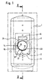
- a boiler 1 filled with water for the preparation of Hot water for heating systems and the sanitary area has a central oil burner 2 with a combustion chamber 3 and a cover arranged at the front of the boiler 1 4 on.
- a Flue gas extractor 6 is arranged, through which the combustion evolving flue gas to the chimney.
- heat exchangers or boiler may be provided, especially above and below the combustion chamber 3, as shown in Figure 2.
- the combustion chamber 3 has a circular cross section and is essentially cylindrical. At hers The top of the combustion chamber has 3 exhaust openings 7, through which the flue gas can reach the flue gas outlet 6.
- the Combustion chamber 3 is on the front side of the boiler 1 attached to the boiler 1 via holding devices 8, 9. Between the combustion devices 3 have the holding devices 8, 9 an opening 11 through which the tip of the oil burner 2 can be inserted into the combustion chamber 3.
- the combustion chamber 3 can also on a heat storage of the heating system or be welded to the boiler 1.
- the combustion chamber 3 is at a short distance from its outer wall 12 in the area of the bottom 13 and a side wall 14 of the Combustion chamber surrounded by a wall 16, which accordingly the circular cylindrical shape of the combustion chamber 3 as a shell Half cylinder 17 is formed.
- the half cylinder 17 has a cross section that corresponds to a segment of a circle. The circle segment can also in other embodiments be smaller or larger than a semicircle.
- the half cylinder 17 is via holding devices 18 at the front of the Boiler 1 attached independently of the combustion chamber 3.
- the half cylinder 17 can also on the front of the Boiler 1 or on a heat storage of the heating system be welded on.
- the half cylinder 17 is axial Direction so long that the wall 16 to about protrudes rear end 21 of the combustion chamber 3.
- the storage water flowing through the space 22 becomes heated by the combustion chamber 3 and forms a thermal cushion compared to the rest of the storage water in container 1.
- the temperature of the wall 12 of the combustion chamber 3 is thereby in the area of the wall 16 relatively high and is particularly at a temperature that is practical no condensation forms.
- a simple metal sheet can in particular be used as the half cylinder 17 serve which can be produced inexpensively and easily is to be assembled.
- the invention can thus be particularly favorable way to prevent the formation of condensation and thereby corrosion of the combustion chamber 3 largely be prevented.
Landscapes
- Engineering & Computer Science (AREA)
- Physics & Mathematics (AREA)
- Thermal Sciences (AREA)
- Chemical & Material Sciences (AREA)
- Combustion & Propulsion (AREA)
- Mechanical Engineering (AREA)
- General Engineering & Computer Science (AREA)
- Sorption Type Refrigeration Machines (AREA)
- General Induction Heating (AREA)
- Heat-Pump Type And Storage Water Heaters (AREA)
- Cookers (AREA)
- Gas Burners (AREA)
Claims (7)
- Installation de chauffage comportant un récipient (1) servant d'accumulateur de chaleur et rempli avec de l'eau à titre de fluide accumulateur de chaleur, et une chambre de combustion (3) prévue dans le récipient et présentant une section transversale circulaire pour chauffer l'eau d'accumulation par combustion d'un combustible, la chambre de combustion (3) étant entourée au moins sur sa face inférieure à faible distance par une paroi (16) de section transversale en forme de cercle partiel, l'espace formé entre la chambre de combustion (3) et la paroi (16) étant ouvert vers le récipient (1),
caractérisée en ce que la paroi (16) est tirée vers le haut jusqu'à la moitié de la hauteur de la chambre de combustion (3) sur un seul côté de la chambre de combustion (3), et en ce que sur ce côté de la chambre de combustion (3) la paroi (16) est tirée vers le haut plus loin que sur le côté de la chambre de combustion (3) opposé à celui-ci. - Installation de chauffage selon la revendication 1, caractérisée en ce que la distance entre la paroi (16) et la chambre de combustion (3) est comprise entre environ 2 mm et environ 5 mm.
- Installation de chauffage selon l'une des revendications précédentes, caractérisée en ce que la chambre de combustion (3) est réalisée sous forme de chambre de combustion dite à faible dégagement de NOx.
- Installation de chauffage selon la revendication 3, caractérisée en ce que la chambre de combustion (3) est réalisée sous forme de chaudière dite à trois tirages.
- Installation de chauffage selon l'une des revendications précédentes, caractérisée en ce que le récipient (1) est susceptible d'être relié à des radiateurs via des conduites d'allée et de retour (26, 27) en formant un circuit, et en ce qu'il est prévu au moins un échangeur de chaleur supérieur à courant continu (28) agencé dans la zone supérieure du récipient (1) pour chauffer l'eau fraíche, qui est disposé en série avec un échangeur de chaleur inférieur à courant continu (29) agencé dans la zone inférieure du récipient (1) pour préchauffer l'eau fraíche, la chambre de combustion (3) étant agencée entre l'échangeur de chaleur supérieur à courant continu (28) et l'échangeur de chaleur inférieur à courant continu (29);
- Installation de chauffage selon la revendication 5, caractérisée en ce qu'il est prévu au moins un puits vertical respectif (31, 32) dans là zone de l'échangeur de chaleur supérieur à courant continu (28) et/ou dans la zone de l'échangeur de chaleur inférieur à courant continu (29).
- Installation de chauffage selon la revendication 6, caractérisée en ce que l'ouverture inférieure (33) du puits supérieur (31) est disposée au-dessus de la chambre de combustion (3).
Applications Claiming Priority (2)
| Application Number | Priority Date | Filing Date | Title |
|---|---|---|---|
| DE29622446U DE29622446U1 (de) | 1996-12-31 | 1996-12-31 | Heizungsanlage |
| DE29622446U | 1996-12-31 |
Publications (3)
| Publication Number | Publication Date |
|---|---|
| EP0851180A2 EP0851180A2 (fr) | 1998-07-01 |
| EP0851180A3 EP0851180A3 (fr) | 1999-11-17 |
| EP0851180B1 true EP0851180B1 (fr) | 2004-01-14 |
Family
ID=8033819
Family Applications (1)
| Application Number | Title | Priority Date | Filing Date |
|---|---|---|---|
| EP97113483A Expired - Lifetime EP0851180B1 (fr) | 1996-12-31 | 1997-08-05 | Installation de chauffage |
Country Status (3)
| Country | Link |
|---|---|
| EP (1) | EP0851180B1 (fr) |
| AT (1) | ATE257933T1 (fr) |
| DE (2) | DE29622446U1 (fr) |
Families Citing this family (1)
| Publication number | Priority date | Publication date | Assignee | Title |
|---|---|---|---|---|
| CN108826683B (zh) * | 2018-08-29 | 2023-08-08 | 浙江格洛维能源科技有限公司 | 一种内外螺旋换热结构的高碳分子发热油电热水器 |
Family Cites Families (4)
| Publication number | Priority date | Publication date | Assignee | Title |
|---|---|---|---|---|
| DE7508469U (de) * | 1975-03-18 | 1977-05-05 | Viessmann, Hans, 3559 Battenberg | Geraet zur erzeugung von heissem wasser |
| DE3412331C1 (de) * | 1984-04-03 | 1985-10-31 | Interdomo GmbH & Co Heizungs- und Wärmetechnik, 4407 Emsdetten | Heizkessel für Niedertemperaturheizungen |
| FR2629907A1 (fr) * | 1988-04-06 | 1989-10-13 | Collard A Trolart G | Perfectionnements aux echangeurs thermiques |
| DD280375A1 (de) * | 1989-03-02 | 1990-07-04 | Ve Kom Haus U Kuechengeraete S | Warmwasserbereiter mit leiteinrichtung |
-
1996
- 1996-12-31 DE DE29622446U patent/DE29622446U1/de not_active Expired - Lifetime
-
1997
- 1997-08-05 EP EP97113483A patent/EP0851180B1/fr not_active Expired - Lifetime
- 1997-08-05 AT AT97113483T patent/ATE257933T1/de not_active IP Right Cessation
- 1997-08-05 DE DE59711213T patent/DE59711213D1/de not_active Expired - Fee Related
Also Published As
| Publication number | Publication date |
|---|---|
| EP0851180A3 (fr) | 1999-11-17 |
| EP0851180A2 (fr) | 1998-07-01 |
| DE29622446U1 (de) | 1997-03-06 |
| ATE257933T1 (de) | 2004-01-15 |
| DE59711213D1 (de) | 2004-02-19 |
Similar Documents
| Publication | Publication Date | Title |
|---|---|---|
| CH616499A5 (en) | Central heating system with a boiler and an additional heat exchanger for preheating the medium flowing back to the boiler | |
| DE2102024C3 (de) | Dampferzeuger | |
| EP0851180B1 (fr) | Installation de chauffage | |
| LU82314A1 (de) | Zweikammer-heizkessel fuer brennerfeuerung und festbrennstoff-feuerung | |
| DE3238603C2 (fr) | ||
| EP0275401B1 (fr) | Chaudière et procédure pour exploiter cette chaudière | |
| DE4223799C2 (de) | Gasheizgerät | |
| EP0166703B1 (fr) | Chaudière | |
| DE69623834T2 (de) | Wärmetauscher mit universellem Verbrennungsraum und Kondensatablauf | |
| DE624892C (de) | Wassergekuehlter Vorschubrost | |
| DE3108452C2 (de) | Öl/Gas-Heizkessel | |
| DE2942167C2 (de) | Brennkammer für einen mit flüssigen oder gasförmigen Brennstoffen beheizten Heizkessel | |
| EP0031571B1 (fr) | Chaudière de chauffage | |
| DE3221724C2 (de) | Brat-, back- und/oder kocheinrichtung | |
| DE3111084A1 (de) | Kamin | |
| DE3231211A1 (de) | Einrichtung fuer eine brennkammer mit einem oel- oder gasbrenner | |
| EP0217320A2 (fr) | Chaudière pour combustibles liquides ou gazéiformes | |
| DE3044088C2 (de) | Ofen zum Erhitzen eines Strömungsmittels, insbesondere Wasser oder Luft | |
| EP0319009B1 (fr) | Ballon d'eau chaude | |
| DE4111232C2 (fr) | ||
| EP0059898A2 (fr) | Méthode pour l'utilisation d'une installation de chauffage central à eau chaude avec un échangeur de chaleur séparé pour les gaz de combustion | |
| DE6610039U (de) | Flammrohr-rauchrohrkessel, insbesondere mit oel- oder gasfeuerung. | |
| AT393023B (de) | Heizungsanlage | |
| DE1751305A1 (de) | Flammrohr-Rauchrohrkessel,insbesondere mit OEl- oder Gasfeuerung | |
| DE19947294A1 (de) | Heizkessel |
Legal Events
| Date | Code | Title | Description |
|---|---|---|---|
| PUAI | Public reference made under article 153(3) epc to a published international application that has entered the european phase |
Free format text: ORIGINAL CODE: 0009012 |
|
| AK | Designated contracting states |
Kind code of ref document: A2 Designated state(s): AT CH DE FR IT LI |
|
| AX | Request for extension of the european patent |
Free format text: AL;LT;LV;RO;SI |
|
| PUAL | Search report despatched |
Free format text: ORIGINAL CODE: 0009013 |
|
| AK | Designated contracting states |
Kind code of ref document: A3 Designated state(s): AT BE CH DE DK ES FI FR GB GR IE IT LI LU MC NL PT SE |
|
| AX | Request for extension of the european patent |
Free format text: AL;LT;LV;RO;SI |
|
| AKX | Designation fees paid | ||
| 17P | Request for examination filed |
Effective date: 20000517 |
|
| RBV | Designated contracting states (corrected) |
Designated state(s): AT CH DE FR IT LI |
|
| REG | Reference to a national code |
Ref country code: DE Ref legal event code: 8566 |
|
| 17Q | First examination report despatched |
Effective date: 20020313 |
|
| GRAH | Despatch of communication of intention to grant a patent |
Free format text: ORIGINAL CODE: EPIDOS IGRA |
|
| GRAS | Grant fee paid |
Free format text: ORIGINAL CODE: EPIDOSNIGR3 |
|
| GRAA | (expected) grant |
Free format text: ORIGINAL CODE: 0009210 |
|
| AK | Designated contracting states |
Kind code of ref document: B1 Designated state(s): AT CH DE FR IT LI |
|
| REG | Reference to a national code |
Ref country code: CH Ref legal event code: EP |
|
| REF | Corresponds to: |
Ref document number: 59711213 Country of ref document: DE Date of ref document: 20040219 Kind code of ref document: P |
|
| ET | Fr: translation filed | ||
| PLBE | No opposition filed within time limit |
Free format text: ORIGINAL CODE: 0009261 |
|
| STAA | Information on the status of an ep patent application or granted ep patent |
Free format text: STATUS: NO OPPOSITION FILED WITHIN TIME LIMIT |
|
| 26N | No opposition filed |
Effective date: 20041015 |
|
| PGFP | Annual fee paid to national office [announced via postgrant information from national office to epo] |
Ref country code: FR Payment date: 20050825 Year of fee payment: 9 |
|
| PGFP | Annual fee paid to national office [announced via postgrant information from national office to epo] |
Ref country code: IT Payment date: 20060831 Year of fee payment: 10 |
|
| REG | Reference to a national code |
Ref country code: FR Ref legal event code: ST Effective date: 20070430 |
|
| PG25 | Lapsed in a contracting state [announced via postgrant information from national office to epo] |
Ref country code: FR Free format text: LAPSE BECAUSE OF NON-PAYMENT OF DUE FEES Effective date: 20060831 |
|
| PGFP | Annual fee paid to national office [announced via postgrant information from national office to epo] |
Ref country code: AT Payment date: 20080829 Year of fee payment: 12 |
|
| PGFP | Annual fee paid to national office [announced via postgrant information from national office to epo] |
Ref country code: DE Payment date: 20081030 Year of fee payment: 12 Ref country code: CH Payment date: 20081127 Year of fee payment: 12 |
|
| PG25 | Lapsed in a contracting state [announced via postgrant information from national office to epo] |
Ref country code: IT Free format text: LAPSE BECAUSE OF NON-PAYMENT OF DUE FEES Effective date: 20070805 |
|
| REG | Reference to a national code |
Ref country code: CH Ref legal event code: PL |
|
| PG25 | Lapsed in a contracting state [announced via postgrant information from national office to epo] |
Ref country code: LI Free format text: LAPSE BECAUSE OF NON-PAYMENT OF DUE FEES Effective date: 20090831 Ref country code: CH Free format text: LAPSE BECAUSE OF NON-PAYMENT OF DUE FEES Effective date: 20090831 |
|
| PG25 | Lapsed in a contracting state [announced via postgrant information from national office to epo] |
Ref country code: AT Free format text: LAPSE BECAUSE OF NON-PAYMENT OF DUE FEES Effective date: 20090805 |
|
| PG25 | Lapsed in a contracting state [announced via postgrant information from national office to epo] |
Ref country code: DE Free format text: LAPSE BECAUSE OF NON-PAYMENT OF DUE FEES Effective date: 20100302 |