EP0851254A1 - Appareil pour la répartition et le stockage de fibres optiques - Google Patents
Appareil pour la répartition et le stockage de fibres optiques Download PDFInfo
- Publication number
- EP0851254A1 EP0851254A1 EP97122548A EP97122548A EP0851254A1 EP 0851254 A1 EP0851254 A1 EP 0851254A1 EP 97122548 A EP97122548 A EP 97122548A EP 97122548 A EP97122548 A EP 97122548A EP 0851254 A1 EP0851254 A1 EP 0851254A1
- Authority
- EP
- European Patent Office
- Prior art keywords
- vertical
- channel
- side flanges
- routing
- storage apparatus
- Prior art date
- Legal status (The legal status is an assumption and is not a legal conclusion. Google has not performed a legal analysis and makes no representation as to the accuracy of the status listed.)
- Withdrawn
Links
- 239000013307 optical fiber Substances 0.000 title claims abstract description 40
- 230000000712 assembly Effects 0.000 claims abstract description 42
- 238000000429 assembly Methods 0.000 claims abstract description 42
- 239000000835 fiber Substances 0.000 claims description 17
- 230000007246 mechanism Effects 0.000 claims description 16
- 239000000428 dust Substances 0.000 claims description 14
- 238000005452 bending Methods 0.000 description 5
- 230000008859 change Effects 0.000 description 4
- 238000004519 manufacturing process Methods 0.000 description 3
- 239000000853 adhesive Substances 0.000 description 2
- 230000001070 adhesive effect Effects 0.000 description 2
- 239000000463 material Substances 0.000 description 2
- 239000002184 metal Substances 0.000 description 2
- 229910052751 metal Inorganic materials 0.000 description 2
- 239000004033 plastic Substances 0.000 description 2
- 229920003023 plastic Polymers 0.000 description 2
- 238000007493 shaping process Methods 0.000 description 2
- 230000007704 transition Effects 0.000 description 2
- RYGMFSIKBFXOCR-UHFFFAOYSA-N Copper Chemical compound [Cu] RYGMFSIKBFXOCR-UHFFFAOYSA-N 0.000 description 1
- 230000003213 activating effect Effects 0.000 description 1
- 230000005540 biological transmission Effects 0.000 description 1
- 238000011109 contamination Methods 0.000 description 1
- 229910052802 copper Inorganic materials 0.000 description 1
- 239000010949 copper Substances 0.000 description 1
- 239000003000 extruded plastic Substances 0.000 description 1
- 231100001261 hazardous Toxicity 0.000 description 1
- 238000009434 installation Methods 0.000 description 1
- 150000002739 metals Chemical class 0.000 description 1
- 230000004048 modification Effects 0.000 description 1
- 238000012986 modification Methods 0.000 description 1
- 230000003287 optical effect Effects 0.000 description 1
- 230000002028 premature Effects 0.000 description 1
- 230000008707 rearrangement Effects 0.000 description 1
- 230000008054 signal transmission Effects 0.000 description 1
- 238000006467 substitution reaction Methods 0.000 description 1
Images


Classifications
-
- G—PHYSICS
- G02—OPTICS
- G02B—OPTICAL ELEMENTS, SYSTEMS OR APPARATUS
- G02B6/00—Light guides; Structural details of arrangements comprising light guides and other optical elements, e.g. couplings
- G02B6/44—Mechanical structures for providing tensile strength and external protection for fibres, e.g. optical transmission cables
- G02B6/4439—Auxiliary devices
- G02B6/444—Systems or boxes with surplus lengths
- G02B6/4453—Cassettes
- G02B6/4454—Cassettes with splices
-
- G—PHYSICS
- G02—OPTICS
- G02B—OPTICAL ELEMENTS, SYSTEMS OR APPARATUS
- G02B6/00—Light guides; Structural details of arrangements comprising light guides and other optical elements, e.g. couplings
- G02B6/44—Mechanical structures for providing tensile strength and external protection for fibres, e.g. optical transmission cables
- G02B6/4439—Auxiliary devices
- G02B6/444—Systems or boxes with surplus lengths
- G02B6/4452—Distribution frames
- G02B6/44524—Distribution frames with frame parts or auxiliary devices mounted on the frame and collectively not covering a whole width of the frame or rack
-
- G—PHYSICS
- G02—OPTICS
- G02B—OPTICAL ELEMENTS, SYSTEMS OR APPARATUS
- G02B6/00—Light guides; Structural details of arrangements comprising light guides and other optical elements, e.g. couplings
- G02B6/44—Mechanical structures for providing tensile strength and external protection for fibres, e.g. optical transmission cables
- G02B6/4439—Auxiliary devices
- G02B6/444—Systems or boxes with surplus lengths
- G02B6/44528—Patch-cords; Connector arrangements in the system or in the box
-
- G—PHYSICS
- G02—OPTICS
- G02B—OPTICAL ELEMENTS, SYSTEMS OR APPARATUS
- G02B6/00—Light guides; Structural details of arrangements comprising light guides and other optical elements, e.g. couplings
- G02B6/44—Mechanical structures for providing tensile strength and external protection for fibres, e.g. optical transmission cables
- G02B6/4439—Auxiliary devices
- G02B6/4471—Terminating devices ; Cable clamps
- G02B6/4478—Bending relief means
Definitions
- This invention relates to optical wave guides also known as optical fibers. In one aspect it relates to an apparatus for the vertical routing and storage of optical fibers between distribution frames.
- Optical fibers are increasingly preferred over copper wires for the transmission of telecommunication signals and other data.
- optical fiber networks are increasingly being utilized in the so-called premises market to provide signal transmission between groups of nearby buildings, such as a university or business campus, and even for intra-building connections of telephone systems, computer networks and other such office systems.
- Optical fiber connection apparatus also known as distribution frames, are used wherever the interconnection or cross-connection of multiple optical fibers is required, such as where an optical fiber cable comprising numerous individual fibers enters a building for connection to the individual optical fibers of the building's computer network.
- the distribution frame will generally contain a combination of patch panels, splice housing, hubs, routers, and other equipment. All of the equipment may reside in a single vertical frame or rack, or it may take up two or more racks. In either case, short lengths of optical fiber known as jumpers must be routed vertically along the front side of the rack or between racks to connect equipment. Additionally, the cables that feed the equipment from behind the rack must transition down the side of the rack to reach the equipment.
- a vertical routing and storage apparatus also known as an inter-bay routing and storage unit, to provide the room and cable management elements necessary for the vertical routing of jumpers and other optical fibers around the equipment in a distribution frame.
- the vertical routing and storage apparatus can be positioned between adjacent racks, along the side of a free-standing rack, or along the side of the last rack at the end of a line-up of racks.
- various cable management element on vertical routing and storage apparatus to facilitate the support and routing of the fibers. Some such apparatus simply provide spools on the front side to store slack fiber from the jumpers. This keeps the installation neat when one or more jumpers are longer than the exact length necessary to make a given connection.
- Other such vertical routing and storage apparatus may have a number of assemblies forming "D" or "C" shaped channels (when viewed from above) through which the jumpers are routed. These channel help to keep the jumpers organized and, since the jumpers that are being routed down through the channel must be laid over its edge, the channel partially supports the weight of the jumpers. If, however, the vertical location of a channel is poorly placed relative to the location of the equipment in the adjacent frame, then jumpers to be routed downward through the channel may either hang unsupported or be forced to make an otherwise unnecessary transition upward around the next channel above the equipment before being routed downward through the channel. A need therefore exists, for a vertical routing and storage apparatus having channel assemblies which are vertically adjustable to conform with the vertical position of adjacent equipment.
- a vertical routing and storage apparatus for optical fibers comprises an upright member that is adapted for connection to a supporting frame member.
- a plurality of channel assemblies are adjustably mounted along the upright member such that the assemblies can be slidably adjusted up and down relative to the upright member.
- the channel assemblies are suitable for routing a plurality of fiber optic jumper cables therethrough.
- a vertical routing and storage apparatus for optical fibers.
- the vertical routing and storage apparatus comprises an upright member having front and rear vertical faces, a plurality of front channel assemblies adjustably mounted to the front vertical face, and a plurality of rear channel assemblies mounted to the rear vertical face.
- the upright member is adapted for connection to a supporting frame member and has a plurality of vertically oriented slots formed in the front vertical face.
- Each front channel assembly has a vertical position which is a adjustable through a range of vertical positions corresponding to the vertical extent of one of the vertical slots.
- Optical fibers can be routed vertically through the front and rear channels of the routing and storage apparatus and the vertical positions and spacing of the front channel assemblies can be adjusted to advantageously correspond to the vertical positions of optical fiber source equipment adjacent to the front of the apparatus.
- the channel assemblies include side flanges having an interior wall facing the channel and an inwardly convex surface. This curved surface prevents the fibers from violating their minimum bending radius.
- the inwardly convex surfaces of the interior wall has, when viewed in cross section, a radius within the range of about 0.75 inches. This generally corresponds with the range of permissible bend radius for a fiber optic jumper cable.
- the side flanges further comprise an exterior wall facing away from the channel and a radiused insert attached to the exterior wall and forming the interior wall.
- the vertical routing and storage apparatus further comprises a plurality of spool mounting holes formed in the front vertical face and a storage spool demountably attached to the front vertical face at one of the spool mounting holes.
- the channel assemblies further comprise a cross member having a first end pivotally attached to one of the side flanges and a second end being releasably securable to the other of the side flanges, whereby the position of the cross member can be selectively moved from an open position, which provides an enhanced access to the channel for the positioning of optical fibers, to a closed position, which provides increased security for the storage of optical fibers.
- the vertical routing and storage apparatus further comprises a dust cap storage cup including a storage cavity and a mechanism for releasably connecting the cup to a side flange, whereby dust caps from nearby equipment can be advantageously stored in the cup.
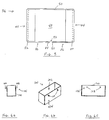
- FIG. 1 a partial front view of a fiber optic distribution facility or distribution frame 20 is shown which includes a VRS apparatus 25.
- a typical distribution frame such as frame 20 comprises one or more vertical equipment stacks 22, also known as racks or bays, each comprising several components supported by vertical frame members 24.
- the frame members 24 may be attached to a wall or free standing on the floor.
- the distribution frame 20 shown in FIG. 1 comprises two equipment bays 22, each including several connector panels 26 and horizontal raceways 28 with a VRS apparatus 25 positioned between equipment bays 22.
- a number of optical fibers 29 are shown being routed horizontally between bays 22 and vertically through channel assemblies 36 on the VRS apparatus 25. Also shown are excess lengths of the fibers 29, known as slack, being looped around a spool 62 for storage. Note that in the example shown in FIG. 1, the vertical position of the channel assembly designated 36a is not well matched to the vertical position of the connector panel designated 26a, therefore the fibers routed therebetween, designated 29a, are relatively unsupported. The occurrence of such vertical mismatch between fiber connection equipment and the channels of a VRS apparatus is relatively common with prior art apparatus having only fixed channels. The current invention, however, provides for vertically adjustable channels to address the vertical mismatch problem.
- VRS apparatus 25 comprises an upright member 30 having front and rear vertical surfaces 32, 34, respectively, a plurality of front channel assemblies 36 adjustably mounted to the front vertical face 32, and a plurality of rear channel assemblies 38 mounted to the rear vertical face 34.
- Upright member 30 is adapted for connection to a supporting frame member (not shown), such as the distribution frame member 24 (shown in FIG. 1). In the embodiment shown in FIGS.
- a plurality of mounting holes 40 are formed in upright member 30 to facilitate connection to a supporting frame member by means of bolts, screws or other fasteners, however, it will be readily apparent that upright member 30 could be otherwise adapted for connection to a supporting frame as is known in the art without departing from the scope of the current invention.
- a plurality of vertically oriented slots 42 are formed in front vertical face 32 of VRS apparatus 25.
- Each of the front channel assemblies 36 has a vertical position which is adjustable through a range of vertical positions corresponding to the vertical extent of one of the vertical slots 42.
- the front channel assembly designated 36a has a vertical position, V, which is adjustable through a range of vertical positions, R V , from the uppermost position (shown in solid lines) designated as V 1 , to the lower-most position (shown in phantom) designated as V 2 .
- the range R V corresponds to the vertical extent of one of the vertical slots, in this case, either of the slots marked 42a.
- Each front channel assembly 36 includes two front side flanges 44 and a first front cross member 46.
- the front side flanges 44 are spaced apart from one another and project outwardly from the front vertical face 32.
- the first front cross member 46 is connected to at least one of the front side flanges 44, thereby defining a front channel 48 generally bounded by the front side flanges 44 and the first front cross member 46.
- the front channel assembly 36 can be adjustably mounted to the vertical slots 42 of upright member 30 in a number of ways.
- a second front cross member 50 is connected between the front side flanges 44 at the rear side of channel 48.
- the second cross member 50 can be adjustably mounted on upright member 30 by means of various fasteners as is known in the art.
- so-called cage nuts are positioned in vertical slots 42.
- the cage nuts have internal threads for receiving a threaded fastener which is passed through a hole formed in second front cross member 50. When the fastener is not tightened, the cage nut can slide in slot 42, thus allowing the second front cross member 50 to slide vertically up and down between the top and bottom of the vertical slot 42.
- front channel assembly 36 When the fastener is tightened, however, the cage nut no longer slides in slot 42, rather it becomes fixed in position, thus securing the front channel assembly 36 in the desired vertical position.
- the vertical position and spacing of front channel assemblies 36 can thus be adjusted to advantageously correspond to the vertical positions of optical fibers from sources adjacent to front vertical face 32.
- Front channel assemblies are removable and can either not be used or moved to another pair of slots. Additionally, more than one channel assembly can be used in a pair of slots.
- rear channel assemblies 38 are similar to the front channel assemblies 36, with each rear channel assembly 38 having two rear side flanges 52 and a rear cross member 54.
- the rear side members 52 are spaced apart from one another and project outwardly from the rear vertical face 34.
- Rear cross-member 54 is connected to at least one of the rear side faces 52, thereby defining a rear channel 56 bounded by the rear side flanges 52 and the rear cross member 54.
- the rear channel assemblies 38 are fixedly connected to rear vertical face 34 instead of adjustably connected because the small number of larger cables typically routed on the rear side of a distribution frame do not require precise location of cable management features as do the jumper cables used on the front side. As such is may be easier and less costly to manufacture the back side without accommodating for adjustable assemblies. Rear channels are removable should they not be needed or if they interfere with routing of a large cable or conduit. Further, it will be readily apparent that VRS apparatus having rear channel assemblies which are adjustably mounted to the rear vertical face are within the scope of the current invention.
- vertically adjustable rear channel assemblies can be provided for mounting to the vertical slots 42 from the rear vertical face 34, since the vertical slots 42, while being formed in the front vertical face 32, can also be accessed from the rear vertical face 34. This would allow vertically adjustable channel assemblies to be mounted on both faces of the VRS apparatus.
- a plurality of spool mounting holes 60 can be formed in the front vertical face 32 and a storage spool 62 can be demountably attached to the front vertical face 32 at one of the spool mounting holes 60.
- the spool 62 can be demountably attached to front vertical face 32 using threaded fasteners such as bolts or screws inserted through the spool mounting holes 60.
- four storage spools 62 are provided.
- Feed-through holes 63 formed through vertical member 30 can also be provided allowing cables or fibers (not shown) to be routed from one side of VRS apparatus 25 to the other.
- rubber or plastic grommets can be positioned in feed-through holes 63 to protect the fibers from being damaged by the edges of the hole.
- each front side flange 44 further comprises an interior wall 66, which faces the front channel 48, and an exterior wall 70, which faces away from the front channel.
- Interior wall 66 has an inwardly convex (with respect to the channel 48) surface 68 that is radiused to prevent excessive bending of the fibers 29 routed there across.
- the inwardly convex surface 68 of the interior wall 66 has, when viewed in cross section (as shown in FIG. 4), a radius R W within the range of about 0.75 inches. This corresponds to the range of the permissible bend radius of fiber optic jumper cables.
- front side flanges 44 comprise flat metal parts, however, as is often the case with optical fiber equipment, the direct shaping approach can present manufacturing difficulties, especially when trying to avoid so-called bullet ends on the inwardly facing side of the flanges.
- front side flanges 44 comprise an exterior wall 70 facing away from the channel 48 and a radiused insert 72 connected to the exterior wall.
- the radiused insert 72 which can be formed of various materials known in the art including metals and plastics, is preferably formed of extruded plastic which can be conveniently cut to the proper length.
- Radiused insert 72 is attached to exterior wall 70 thereby forming interior wall 66 having the desired inwardly convex surface 68.
- radiused inserts 72 have chamfered ends 74 and notches 76 sized to facilitate convenient snap-on attachment to exterior wall 70, however, other means for the attachment of radiused inserts 72 to exterior walls 70, including adhesives, screws, bolts and other such fastenings known in the art, can be used without departing from the scope of the current invention. It will also be readily apparent that while the foregoing description relates specifically to the front side flanges 44 and front channel assemblies 36 of VRS apparatus 25, it can further be applied to the rear side flanges 52 and rear channel assemblies 38 without significant change.
- the first front cross member 46 further comprises a first end 78 which is pivotally attached to one of the front side flanges 44 and a second end 80 which is releasably securable to the other of the front side flanges 44.
- a hinge 79 is provided for connecting first end 78 to side flange 44. The position of the front cross member 46 can thus be moved between an open position (shown in phantom in FIG.
- a latch mechanism 81 can be provided for releasably securing second end 80 to the other side flange 44.
- the latch mechanism is preferably a swell latch which expands and contracts, respectively, when an activating lever is pushed in and pulled out, however other latch mechanisms known in the art can be used without departing from the scope of the current invention. While FIG. 3 and the foregoing description relate specifically to a front channel assembly 36, it will be readily apparent that the foregoing description can also be applied to the rear side flanges 52 and rear channel assemblies 38 without significant change.
- the front channel assemblies 36 can further comprise a first front cross member 46 having a fixed end 82 and a free end 84 and a third front cross member 86 having a fixed end 88 and a free end 90.
- the fixed end 82 of the front cross member 46 is connected to one of the front side flanges 44 and the free end 84 extends towards the other of the front side flanges 44.
- the fixed end 88 of the third front cross member 86 is connected to the other of the front side flanges 44 and the free end 90 extends generally toward the free end 84 of the first front cross member 46, thereby defining a gap 92 therebetween.
- Optical fibers may be moved into front channel 48 by passing through the gap 92 between the free ends 84, 90 of the first and third front cross members 46, 86.
- the channel assembly 36 of this embodiment is substantially identical in all other respects to those of previously discussed embodiments. Also, while FIG. 5 and the foregoing description relate specifically to a front channel assembly 36, it will be readily apparent that the foregoing description can also be applied to the rear channel assemblies 38 without significant change.
- the VRS apparatus 25 further comprises a dust cap storage cup 100 which is releasably mounted to one of the front side flanges 44.
- the dust cap storage cup 100 includes a storage cavity 102 and a connecting mechanism 104.
- the storage cavity 102 provides a place where dust caps can be advantageously stored for ready access by personnel working on nearby equipment and to prevent the caps from falling into equipment or onto the floor.
- the connecting mechanism 104 releasably secures the cup 100 to the front side flange 44.
- a compatible connecting mechanism 98 can be provided on front side flanges 44 to cooperate with connecting mechanism 104 of the cup.
- flange connecting mechanism 98 comprises holes 106 formed in the exterior wall 70 of front side flanges 44 and cup connecting mechanism 104 comprises pegs 108 adapted for frictional fit within holes 106.
- the peg-in-hole connecting mechanism used in the current embodiment is simple to manufacture and use, other connecting mechanisms known in the art, including clips, hangers, hook and loop material, and releasable adhesives can also be used to connect the cup 100 to the channel assemblies 36.
- the flange connecting mechanism 98 can be used alone to releasably mount the cup 100 if appropriate. While the foregoing description relates specifically to a cup 100 for mounting on a front channel assembly 36, it will be readily apparent that the cup 100 can also be mounted to the rear channel assemblies 38 without significant change.
Landscapes
- Physics & Mathematics (AREA)
- General Physics & Mathematics (AREA)
- Optics & Photonics (AREA)
- Light Guides In General And Applications Therefor (AREA)
Applications Claiming Priority (2)
| Application Number | Priority Date | Filing Date | Title |
|---|---|---|---|
| US775679 | 1991-10-09 | ||
| US08/775,679 US5758002A (en) | 1996-12-31 | 1996-12-31 | Routing and storage apparatus for optical fibers |
Publications (1)
| Publication Number | Publication Date |
|---|---|
| EP0851254A1 true EP0851254A1 (fr) | 1998-07-01 |
Family
ID=25105162
Family Applications (1)
| Application Number | Title | Priority Date | Filing Date |
|---|---|---|---|
| EP97122548A Withdrawn EP0851254A1 (fr) | 1996-12-31 | 1997-12-19 | Appareil pour la répartition et le stockage de fibres optiques |
Country Status (3)
| Country | Link |
|---|---|
| US (1) | US5758002A (fr) |
| EP (1) | EP0851254A1 (fr) |
| CA (1) | CA2221838A1 (fr) |
Cited By (1)
| Publication number | Priority date | Publication date | Assignee | Title |
|---|---|---|---|---|
| GB2351359A (en) * | 1999-06-25 | 2000-12-27 | Raychem Sa Nv | Optical fibre connection and storage unit |
Families Citing this family (88)
| Publication number | Priority date | Publication date | Assignee | Title |
|---|---|---|---|---|
| USD440210S1 (en) | 1997-08-07 | 2001-04-10 | Ortronics, Inc. | Cable management rack |
| US6269212B1 (en) | 1997-09-18 | 2001-07-31 | Pirelli Cavi E Sistemi S.P.A. | Method for performing fixing inside a container for optical connection components |
| US6468112B1 (en) * | 1999-01-11 | 2002-10-22 | Adc Telecommunications, Inc. | Vertical cable management system with ribcage structure |
| US6556763B1 (en) * | 1999-03-01 | 2003-04-29 | Adc Telecommunications, Inc. | Optical fiber distribution frame with connector modules |
| US6535682B1 (en) | 1999-03-01 | 2003-03-18 | Adc Telecommunications, Inc. | Optical fiber distribution frame with connector modules |
| US6760531B1 (en) | 1999-03-01 | 2004-07-06 | Adc Telecommunications, Inc. | Optical fiber distribution frame with outside plant enclosure |
| US6424781B1 (en) * | 1999-03-01 | 2002-07-23 | Adc Telecommunications, Inc. | Optical fiber distribution frame with pivoting connector panels |
| US6181862B1 (en) * | 1999-03-12 | 2001-01-30 | Siecor Operations Llc | Interbay fiber optic storage unit |
| US6353696B1 (en) * | 1999-03-19 | 2002-03-05 | Corning Cable Systems Llc | Panel for managing jumper storage |
| US6278829B1 (en) * | 1999-05-05 | 2001-08-21 | Marconi Communications, Inc. | Optical fiber routing and support apparatus |
| US6256444B1 (en) * | 1999-09-21 | 2001-07-03 | Antec Corporation | Adjustable guide for organizing optical fibers in an equipment rack |
| US7016835B2 (en) * | 1999-10-29 | 2006-03-21 | International Business Machines Corporation | Speech and signal digitization by using recognition metrics to select from multiple techniques |
| US6330389B1 (en) * | 1999-11-18 | 2001-12-11 | Lucent Technologies, Inc. | System for organizing optical fibers |
| US6316728B1 (en) * | 2000-01-06 | 2001-11-13 | Tyco Electronics Logistics Ag | Cross-connect cabinet |
| US6571047B1 (en) * | 2000-04-18 | 2003-05-27 | Sprint Spectrum, L.P. | Inter-bay fiber management assembly |
| US6501899B1 (en) * | 2000-06-02 | 2002-12-31 | Panduit Corp. | Vertical cable management system |
| US6584267B1 (en) * | 2000-06-02 | 2003-06-24 | Panduit Corp. | Cable management system |
| CA2313895A1 (fr) * | 2000-07-12 | 2002-01-12 | Alcatel Networks Corporation | Appareil de montage sur baie d'equipement comportant un dispositif de controle du rayon de courbure des cables et un conduit de retenue des cables |
| US6487356B1 (en) * | 2000-07-31 | 2002-11-26 | Cisco Technology, Inc. | Fiber optic cable segregation and slack storage apparatus and method |
| US6438311B1 (en) * | 2000-08-14 | 2002-08-20 | Oni Systems Corp. | Cable retainer and cable organizer using same |
| US6633717B1 (en) * | 2000-09-08 | 2003-10-14 | Telect, Inc. | High density fiber optic cable distribution frame system |
| US6489565B1 (en) | 2000-09-15 | 2002-12-03 | Chatsworth Products, Inc. | Vertical cable management rack |
| US7588216B1 (en) * | 2001-03-19 | 2009-09-15 | Cisco Technology, Inc. | Fiber optic cabling management using hook and loop fabric |
| US6553172B2 (en) | 2001-06-08 | 2003-04-22 | Ceyba Inc. | Fiber optic cable routing device with pre-alignment feature |
| US6785459B2 (en) | 2001-06-26 | 2004-08-31 | Adc Telecommunications, Inc. | Cable management brackets and cabinet |
| US20030219194A1 (en) * | 2002-04-19 | 2003-11-27 | Barthel William F. | Optical fiber management system and method |
| US6829425B2 (en) | 2002-04-19 | 2004-12-07 | Plexus Corporation | Optical fiber management system and method |
| US6741785B2 (en) | 2002-04-19 | 2004-05-25 | Plexus Corporation | Optical fiber management system and method |
| US6845206B2 (en) * | 2002-06-11 | 2005-01-18 | Alcoa Fujikura Limited | Interbay housing assembly for fiber optic management systems |
| US7083051B2 (en) * | 2002-11-15 | 2006-08-01 | Adc Telecommunications, Inc. | Cable management assembly, system and method |
| US7142764B2 (en) * | 2003-03-20 | 2006-11-28 | Tyco Electronics Corporation | Optical fiber interconnect cabinets, termination modules and fiber connectivity management for the same |
| US7172078B2 (en) * | 2003-07-09 | 2007-02-06 | Hubbell Incorporated | Column network hardware management system |
| US6946605B2 (en) * | 2003-12-01 | 2005-09-20 | Ortronics, Inc. | Cable management system |
| US6920274B2 (en) * | 2003-12-23 | 2005-07-19 | Adc Telecommunications, Inc. | High density optical fiber distribution frame with modules |
| US7376321B2 (en) * | 2004-08-09 | 2008-05-20 | Adc Telecommunications, Inc. | Modules including multiple rows of adapters for high density optical fiber distribution frame |
| US7362941B2 (en) * | 2005-01-21 | 2008-04-22 | Cooper Technologies, Inc. | Cable management system |
| US7079745B1 (en) * | 2005-02-14 | 2006-07-18 | Sbc Knowledge Ventures, L.P. | Spool assembly for absorbing slack of fiber optic jumpers routed through raceways and network equipment |
| US7260302B2 (en) * | 2005-02-16 | 2007-08-21 | Panduit Corp. | Patch cord management system |
| US7677400B2 (en) * | 2005-04-07 | 2010-03-16 | Adc Telecommunications, Inc. | Cable management assembly, system and method |
| US20060264252A1 (en) * | 2005-05-23 | 2006-11-23 | White Gehrig H | System and method for providing a host console for use with an electronic card game |
| US20070213869A1 (en) * | 2006-02-08 | 2007-09-13 | Intermec Ip Corp. | Cargo transporter with automatic data collection devices |
| US7298951B2 (en) * | 2006-02-16 | 2007-11-20 | Adc Telecommunications, Inc. | Cable management device and method |
| US7498512B2 (en) | 2006-03-13 | 2009-03-03 | Panduit Corp. | Network cabinet |
| US7382961B2 (en) | 2006-05-23 | 2008-06-03 | Telect Inc. | Fiber transitioning |
| US8106311B2 (en) * | 2006-07-20 | 2012-01-31 | Ortronics, Inc. | Cable pathway patch rack with waterfall member |
| US7601922B2 (en) * | 2006-07-20 | 2009-10-13 | Ortronics, Inc. | Cable pathway patch panel rack with waterfall base |
| US20080023212A1 (en) * | 2006-07-20 | 2008-01-31 | Larsen Lars R | Cable pathway patch panel rack |
| US7369740B2 (en) * | 2006-08-25 | 2008-05-06 | Adc Telecommunications, Inc. | Cable management system with spring latch |
| US7764857B2 (en) * | 2006-08-25 | 2010-07-27 | Adc Telecommunications, Inc. | Cable management system with twist latch |
| US7623750B2 (en) * | 2006-11-29 | 2009-11-24 | Panduit Corp. | Bend radius post |
| US8119915B2 (en) * | 2007-10-05 | 2012-02-21 | Leviton Manufacturing Co., Inc. | Cable management patch panel system with vertical ducting |
| US7406242B1 (en) | 2007-11-16 | 2008-07-29 | Tyco Electronics Co., Ltd. | Interconnect enclosures for optical fibers including cross-connect modules and methods for using the same |
| GB2468823B (en) * | 2008-01-07 | 2012-10-24 | Chatsworth Prod Inc | Vertical cable manager |
| AU2009204505A1 (en) * | 2008-01-07 | 2009-07-16 | Chatsworth Products, Inc. | Apparatus and method for organizing cables in a cabinet |
| US8263867B2 (en) * | 2008-01-07 | 2012-09-11 | Chatsworth Products, Inc. | Cable management accessories |
| US8215498B2 (en) * | 2008-04-30 | 2012-07-10 | Raytheon Company | Modular rack system |
| MX2011005380A (es) | 2008-11-21 | 2011-06-06 | Adc Telecommunications Inc | Modulo de telecomunicaciones de fibra optica. |
| US8162700B2 (en) * | 2009-04-17 | 2012-04-24 | Adc Telecommunications, Inc. | Connection block mounting frame |
| JP2011054816A (ja) * | 2009-09-03 | 2011-03-17 | Oki Electric Industry Co Ltd | ケーブル固定構造及び現金自動預払機 |
| US8558113B2 (en) | 2010-01-17 | 2013-10-15 | Chatsworth Products, Inc. | Vertical cable manager |
| US8710369B2 (en) | 2010-01-17 | 2014-04-29 | Chatsworth Products, Inc. | Horizontal cable manager |
| US8958679B2 (en) | 2010-03-02 | 2015-02-17 | Tyco Electronics Services Gmbh | Fibre-optic telecommunications module |
| EP2429272A2 (fr) | 2010-09-10 | 2012-03-14 | Chatsworth Products, Inc. | Panneau de passage de câbles pour enceinte d'équipement électronique |
| US8901438B2 (en) | 2010-09-10 | 2014-12-02 | Chatsworth Products, Inc. | Electronic equipment cabinet structure |
| US8787023B2 (en) | 2010-09-10 | 2014-07-22 | Chatsworth Products, Inc. | Rail mounting clamp for electronic equipment enclosure |
| US9417418B2 (en) | 2011-09-12 | 2016-08-16 | Commscope Technologies Llc | Flexible lensed optical interconnect device for signal distribution |
| US8770861B2 (en) | 2011-09-27 | 2014-07-08 | Tyco Electronics Corporation | Outside plant termination enclosure |
| CN103917904A (zh) | 2011-10-07 | 2014-07-09 | Adc电信公司 | 光纤盒、系统和方法 |
| US8882536B2 (en) | 2012-01-27 | 2014-11-11 | Chatsworth Products, Inc. | Power distribution unit with interchangeable outlet adapter types |
| US20130215581A1 (en) | 2012-01-27 | 2013-08-22 | Chatsworth Products, Inc. | Board-mounted circuit breakers for electronic equipment enclosures |
| US9054449B2 (en) | 2012-01-27 | 2015-06-09 | Chatsworth Products, Inc. | Cable retention system for power distribution unit |
| ES2792122T3 (es) | 2012-09-28 | 2020-11-10 | Commscope Connectivity Uk Ltd | Casete de fibra óptica |
| US9146374B2 (en) | 2012-09-28 | 2015-09-29 | Adc Telecommunications, Inc. | Rapid deployment packaging for optical fiber |
| US9223094B2 (en) | 2012-10-05 | 2015-12-29 | Tyco Electronics Nederland Bv | Flexible optical circuit, cassettes, and methods |
| US9435975B2 (en) | 2013-03-15 | 2016-09-06 | Commscope Technologies Llc | Modular high density telecommunications frame and chassis system |
| EP3100090A4 (fr) | 2014-01-28 | 2017-09-06 | ADC Telecommunications Inc. | Module de connexion de fibres optiques coulissant avec gestion de mou de câble |
| US9494758B2 (en) | 2014-04-03 | 2016-11-15 | Commscope Technologies Llc | Fiber optic distribution system |
| US9470868B2 (en) * | 2014-04-28 | 2016-10-18 | Telect, Inc. | Ultra-high density frames |
| US10003180B1 (en) | 2015-11-30 | 2018-06-19 | Chatsworth Products, Inc. | Cable pathway divider and method for installing same |
| US9829666B2 (en) | 2016-02-17 | 2017-11-28 | Telect, Inc. | Ultra-high density patch systems |
| EP3692404A4 (fr) | 2017-10-02 | 2021-06-16 | Commscope Technologies LLC | Circuit optique et procédé de préparation |
| US11084686B2 (en) * | 2018-01-12 | 2021-08-10 | Prince George Electric Cooperative | Cable storage devices and methods of use thereof |
| NL2022743B1 (en) * | 2019-03-14 | 2020-09-18 | B V Twentsche Kabelfabriek | Distribution frame, in particular an optical distribution frame, and a method for using said distribution frame |
| EP4127799B1 (fr) | 2020-03-31 | 2025-11-19 | CommScope Technologies LLC | Systèmes de gestion de câbles à fibres optiques |
| DE102020003259B4 (de) * | 2020-05-29 | 2025-05-22 | Hauff-Technik Gridcom Gmbh | Stapel aus einer Mehrzahl gleichartiger Patchmodule, Verteilerschrank und Verwendung |
| MX2023002749A (es) | 2020-09-17 | 2023-04-14 | Panduit Corp | Armazon de distribucion optica y empalme que incluye gabinetes. |
| US12363846B1 (en) * | 2023-02-14 | 2025-07-15 | Amazon Technologies, Inc. | Cartridge for interconnectivity among rack-mounted computing components |
| US20260072228A1 (en) * | 2024-09-10 | 2026-03-12 | Afl Telecommunications Llc | Telecommunications panel and fiber management structures |
Citations (6)
| Publication number | Priority date | Publication date | Assignee | Title |
|---|---|---|---|---|
| DE2315485A1 (de) * | 1973-03-28 | 1974-10-17 | Siemens Ag | Nf-verteilergestell fuer einrichtungen der nachrichtenuebertragungstechnik |
| FR2446040A1 (fr) * | 1979-01-03 | 1980-08-01 | Nozick Jacques | Repartiteur de central telephonique |
| EP0637178A1 (fr) * | 1993-07-27 | 1995-02-01 | Alcatel Cable Interface | Répartiteur téléphonique |
| US5402515A (en) * | 1994-03-01 | 1995-03-28 | Minnesota Mining And Manufacturing Company | Fiber distribution frame system, cabinets, trays and fiber optic connector couplings |
| US5458019A (en) * | 1994-04-26 | 1995-10-17 | Siecor Corporation | Fiber optic cable retaining guide |
| US5511144A (en) * | 1994-06-13 | 1996-04-23 | Siecor Corporation | Optical distribution frame |
Family Cites Families (13)
| Publication number | Priority date | Publication date | Assignee | Title |
|---|---|---|---|---|
| US4630886A (en) * | 1984-04-16 | 1986-12-23 | At&T Bell Laboratories | Lightguide distributing unit |
| CA1249741A (fr) * | 1984-10-25 | 1989-02-07 | Michael J. Donaldson | Materiel de raccordement de cable a fibres optiques |
| DE3680465D1 (de) * | 1985-11-12 | 1991-08-29 | Krone Ag | Vorrichtung zur aufbewahrung der fasern von glasfaserkabeln in verteilereinrichtungen im fernmeldenetz. |
| US4911662A (en) * | 1988-12-20 | 1990-03-27 | Northern Telecom Limited | Distribution frame for telecommunications cable |
| US4995688A (en) * | 1989-07-31 | 1991-02-26 | Adc Telecommunications, Inc. | Optical fiber distribution frame |
| US5100221A (en) * | 1990-01-22 | 1992-03-31 | Porta Systems Corp. | Optical fiber cable distribution frame and support |
| US5093885A (en) * | 1990-07-11 | 1992-03-03 | Adc Telecommunications, Inc. | Fiber optic connector module |
| US5179618A (en) * | 1990-07-11 | 1993-01-12 | Adc Telecommunications, Inc. | Fiber optic connector module |
| US5129030A (en) * | 1991-05-30 | 1992-07-07 | At&T Bell Laboratories | Movable lightguide connector panel |
| US5363465A (en) * | 1993-02-19 | 1994-11-08 | Adc Telecommunications, Inc. | Fiber optic connector module |
| US5339379A (en) * | 1993-06-18 | 1994-08-16 | Telect, Inc. | Telecommunication fiber optic cable distribution apparatus |
| TW232757B (en) * | 1994-01-21 | 1994-10-21 | Adc Telecommunications Inc | High-density fiber distribution frame |
| US5519804A (en) * | 1994-06-22 | 1996-05-21 | At&T Corp. | Universal splice tray |
-
1996
- 1996-12-31 US US08/775,679 patent/US5758002A/en not_active Expired - Fee Related
-
1997
- 1997-11-21 CA CA002221838A patent/CA2221838A1/fr not_active Abandoned
- 1997-12-19 EP EP97122548A patent/EP0851254A1/fr not_active Withdrawn
Patent Citations (6)
| Publication number | Priority date | Publication date | Assignee | Title |
|---|---|---|---|---|
| DE2315485A1 (de) * | 1973-03-28 | 1974-10-17 | Siemens Ag | Nf-verteilergestell fuer einrichtungen der nachrichtenuebertragungstechnik |
| FR2446040A1 (fr) * | 1979-01-03 | 1980-08-01 | Nozick Jacques | Repartiteur de central telephonique |
| EP0637178A1 (fr) * | 1993-07-27 | 1995-02-01 | Alcatel Cable Interface | Répartiteur téléphonique |
| US5402515A (en) * | 1994-03-01 | 1995-03-28 | Minnesota Mining And Manufacturing Company | Fiber distribution frame system, cabinets, trays and fiber optic connector couplings |
| US5458019A (en) * | 1994-04-26 | 1995-10-17 | Siecor Corporation | Fiber optic cable retaining guide |
| US5511144A (en) * | 1994-06-13 | 1996-04-23 | Siecor Corporation | Optical distribution frame |
Cited By (1)
| Publication number | Priority date | Publication date | Assignee | Title |
|---|---|---|---|---|
| GB2351359A (en) * | 1999-06-25 | 2000-12-27 | Raychem Sa Nv | Optical fibre connection and storage unit |
Also Published As
| Publication number | Publication date |
|---|---|
| US5758002A (en) | 1998-05-26 |
| CA2221838A1 (fr) | 1998-06-30 |
Similar Documents
| Publication | Publication Date | Title |
|---|---|---|
| US5758002A (en) | Routing and storage apparatus for optical fibers | |
| EP0851255B1 (fr) | Système repartiteur de fibres optiques | |
| US6918786B2 (en) | Angled patch panel with cable support bar for network cable racks | |
| US10955621B2 (en) | Splice tray for optical fibers | |
| US6591053B2 (en) | Fiber optic wall mount cabinet | |
| US10585259B2 (en) | Overhead cable termination arrangement | |
| US7526172B2 (en) | Splitter modules for fiber distribution hubs | |
| US6728461B1 (en) | Optical fiber cable manager | |
| US10732369B2 (en) | Telecommunications enclosure | |
| US20070104449A1 (en) | Fiber management access system | |
| CN1122455A (zh) | 光纤配线装置 | |
| US20170082814A1 (en) | Pivotably attachable fiber optic housing, modular housing system and method | |
| CN102884463A (zh) | 装置和相关的组件以及用于扩大光学纤维罩壳的容量的方法 | |
| US10641980B2 (en) | Rack-mountable fiber optic splice enclosure | |
| JPH11202136A (ja) | オプティカルファイバ用のルーチング及び保管装置 | |
| US20230375796A1 (en) | Systems and methods for managing cables | |
| MXPA01006997A (en) | Vertical cable management system with ribcage structure |
Legal Events
| Date | Code | Title | Description |
|---|---|---|---|
| PUAI | Public reference made under article 153(3) epc to a published international application that has entered the european phase |
Free format text: ORIGINAL CODE: 0009012 |
|
| 17P | Request for examination filed |
Effective date: 19971219 |
|
| AK | Designated contracting states |
Kind code of ref document: A1 Designated state(s): DE FR GB IT |
|
| AX | Request for extension of the european patent |
Free format text: AL;LT;LV;MK;RO;SI |
|
| AKX | Designation fees paid |
Free format text: DE FR GB IT |
|
| RBV | Designated contracting states (corrected) |
Designated state(s): DE FR GB IT |
|
| 17Q | First examination report despatched |
Effective date: 19990802 |
|
| STAA | Information on the status of an ep patent application or granted ep patent |
Free format text: STATUS: THE APPLICATION IS DEEMED TO BE WITHDRAWN |
|
| 18D | Application deemed to be withdrawn |
Effective date: 20010107 |