EP0851263A2 - Projecteur à valve de lumière avec un écran fluorescent - Google Patents
Projecteur à valve de lumière avec un écran fluorescent Download PDFInfo
- Publication number
- EP0851263A2 EP0851263A2 EP97118629A EP97118629A EP0851263A2 EP 0851263 A2 EP0851263 A2 EP 0851263A2 EP 97118629 A EP97118629 A EP 97118629A EP 97118629 A EP97118629 A EP 97118629A EP 0851263 A2 EP0851263 A2 EP 0851263A2
- Authority
- EP
- European Patent Office
- Prior art keywords
- light
- projector
- shutter
- fluorescent screen
- beam splitter
- Prior art date
- Legal status (The legal status is an assumption and is not a legal conclusion. Google has not performed a legal analysis and makes no representation as to the accuracy of the status listed.)
- Withdrawn
Links
Images




Classifications
-
- H—ELECTRICITY
- H01—ELECTRIC ELEMENTS
- H01J—ELECTRIC DISCHARGE TUBES OR DISCHARGE LAMPS
- H01J31/00—Cathode ray tubes; Electron beam tubes
- H01J31/08—Cathode ray tubes; Electron beam tubes having a screen on or from which an image or pattern is formed, picked up, converted, or stored
- H01J31/50—Image-conversion or image-amplification tubes, i.e. having optical, X-ray, or analogous input, and optical output
-
- H—ELECTRICITY
- H04—ELECTRIC COMMUNICATION TECHNIQUE
- H04N—PICTORIAL COMMUNICATION, e.g. TELEVISION
- H04N9/00—Details of colour television systems
- H04N9/12—Picture reproducers
- H04N9/31—Projection devices for colour picture display, e.g. using electronic spatial light modulators [ESLM]
- H04N9/3129—Projection devices for colour picture display, e.g. using electronic spatial light modulators [ESLM] scanning a light beam on the display screen
-
- G—PHYSICS
- G02—OPTICS
- G02B—OPTICAL ELEMENTS, SYSTEMS OR APPARATUS
- G02B27/00—Optical systems or apparatus not provided for by any of the groups G02B1/00 - G02B26/00, G02B30/00
- G02B27/28—Optical systems or apparatus not provided for by any of the groups G02B1/00 - G02B26/00, G02B30/00 for polarising
- G02B27/283—Optical systems or apparatus not provided for by any of the groups G02B1/00 - G02B26/00, G02B30/00 for polarising used for beam splitting or combining
-
- G—PHYSICS
- G03—PHOTOGRAPHY; CINEMATOGRAPHY; ANALOGOUS TECHNIQUES USING WAVES OTHER THAN OPTICAL WAVES; ELECTROGRAPHY; HOLOGRAPHY
- G03B—APPARATUS OR ARRANGEMENTS FOR TAKING PHOTOGRAPHS OR FOR PROJECTING OR VIEWING THEM; APPARATUS OR ARRANGEMENTS EMPLOYING ANALOGOUS TECHNIQUES USING WAVES OTHER THAN OPTICAL WAVES; ACCESSORIES THEREFOR
- G03B21/00—Projectors or projection-type viewers; Accessories therefor
- G03B21/54—Accessories
- G03B21/56—Projection screens
- G03B21/60—Projection screens characterised by the nature of the surface
- G03B21/62—Translucent screens
-
- H—ELECTRICITY
- H01—ELECTRIC ELEMENTS
- H01J—ELECTRIC DISCHARGE TUBES OR DISCHARGE LAMPS
- H01J31/00—Cathode ray tubes; Electron beam tubes
- H01J31/08—Cathode ray tubes; Electron beam tubes having a screen on or from which an image or pattern is formed, picked up, converted, or stored
- H01J31/10—Image or pattern display tubes, i.e. having electrical input and optical output; Flying-spot tubes for scanning purposes
Definitions
- the present invention relates to a light shutter projector with a fluorescent screen, which improves picture quality and brightness, and widens user viewing range by utilizing a fluorescent screen deposited with a fluorescent layer irradiatated by light of a predetermined wavelength, and a ferroelectric liquid crystal shutter.
- projectors are devices for projecting an image on a picture screen. Projectors are classified into two types: color cathode-ray tube projectors displaying an image by radiating light emitted from red R, green G, and blue B cathode-ray tubes through an optical system; and projectors using a reflection-type ferroelectric liquid crystal display shutter employing random access memory(RAM) devices.
- RAM random access memory
- the projector comprises red R, green G, and blue B light sources 2, a first condensing lens 4 for converting light radiated from the light sources 2 into beams, a diffuser 5 for diffusing the beams, a polarizing beam splitter(PBS) 6 for selecting and polarizing a predetermined directional light in the incident light passing through the first condensing lens 4 and the diffuser 5, a ferroelectric liquid crystal(FLC) shutter 8 on/off operated according to the polarizing operation of the PBS 6 and comprising a reflecting layer attached a side opposite that facing the PBS 6(backside) and a very large scale integrated(VLSI) circuit having RAM devices attached on each pixel, and an optical system 10 for magnifying and projecting at a predetermined ratio the light reflected from the ferroelectric liquid crystal shutter 8 on a picture screen.
- PBS polarizing beam splitter
- FLC ferroelectric liquid crystal
- lamps able to emit white light e.g., light emitting diodes or metal halide lamps, may be used for the light sources 2.
- the ferroelectric liquid crystal shutter 8 includes FLC pixels each having a RAM device attached thereon, and an aluminum(Al) reflecting layer attached on the backside of the shutter 8.
- the ferroelectric liquid crystal shutter 8 is on/off operated according to the polarizing operation of the PBS 6 by adjusting an optical axis exterior electric field of the FLC.
- the optical system 10 magnifies the image obtained from the ferroelectric liquid crystal shutter 8 through a lens system, then projects the magnified image on a picture screen, thereby obtaining an image of a reflection-type active matrix ferroelectric liquid crystal projection display.
- the projector using the reflection-type ferroelectric liquid crystal shutter 8 employing RAM devices may display natural colors such as red R, green G, and blue B by utilizing a time-sharing operation.
- This type of projector may solve the problem of the response speed when obtaining a dynamic picture image since the projector has the advantages both of the active matrix actively operating each pixel of the ferroelectric liquid crystal by employing RAM devices and of the ferroelectric liquid crystal display having a rapid response speed.
- three reflection-type shutters for red R, green G, and blue B are not required but only one shutter is enough to realize images with the red R, green G, and blue B colors. Accordingly, the structure of the projector is simplified and manufacturing costs are reduced.
- the conventional projector passively emits light. That is, since the image is obtained by reflection or transmission and not by active emission of pixels, user viewing range, picture quality, and brightness are negatively affected. As a result, the conventional projector cannot be used for small-sized projectors but only for large-sized projectors having a screen size of 40 inches or more.
- the present invention has been made in an effort to solve the above problems.
- the present invention provides a light shutter projector, comprising a light shutter projector, comprising: a light source emitting light of a predetermined wavelength; a first condensing lens for converting the light radiated from the light source into beams; a polarizing beam splitter for selecting a predetermined directional light in the incident light passing through the first condensing lens and for polarizing the light; a light shutter display assembly on/off operated according to the polarizing operation of the polarizing beam splitter; a screen/optical assembly having an optical system and a fluorescent screen.
- the light emitted from the light source has a wavelength within the range of 300nm to 450nm.
- the polarizing beam splitter has double refractivity and is made of transparent material suitable for ultraviolet rays.
- the light shutter display assembly is on/off operated in accordance with the polarizing operation of the polarizing beam splitter, the light shutter displayer assembly comprising a light display shutter and a reflecting layer attached on a side of the light display shutter opposite that facing the polarizing beam splitter.
- the light display shutter is selected from the group consisting of a ferroelectric liquid crystal display shutter with a random access memory, a thin film transistor liquid crystal shutter, and a digital mirror display shutter.
- the optical system is disposed between the fluorescent screen and the polarizing beam splitter.
- the fluorescent screen is disposed between the optical system and the polarizing beam splitter.
- the fluorescent screen is formed such that the light, reflected from each pixel of the reflecting layer, exactly corresponds to fluorescent material through the optical system.
- a light shutter projector with a fluorescent screen comprises a light source 12 emitting light of a predetermined wavelength; a first condensing lens 14 for converting the light radiated from the light source 12 into beams; a diffuser 13 for diffusing light from the first condensing lens 14; a polarizing beam splitter 16 for selecting and polarizing a predetermined directional light in the incident light passing through the diffuser 15; a light shutter assembly 18 having a display light shutter 181 and a reflecting layer 182, which is on/off operated according to the polarizing operation of the polarizing beam splitter 16; and an optical/screen assembly 23 having a fluorescent screen 24 deposited with fluorescent material which illuminates by the light, passing through the optical system 21, of a predetermined wavelength and an optical system 21 disposed between the screen 24 and the polarizing beam spiliter 16 for magnifying, at a predetermined ratio, the light reflected from the light shutter assembly 18.
- the light source 12 emits light at a wavelength within the range of 300 to 450nm. Within this range, the light source 12 emits light(i.e., ultraviolet rays) at a wavelength that does not damage the light display shutter 181 while being sufficient to excite the phosphor layer deposited on the fluorescent screen 24.
- the light source 12 is provided with a color glass or a filter 11 for allowing the passage only of light of a wavelength within the range of 300 to 450nm.
- cobalt(Co), nickel(Ni), and iron(Fe) When using color glass, it is preferable to add cobalt(Co), nickel(Ni), and iron(Fe) to lead glass so that visible light can be removed; and when using a filter it is preferable to use a band pass filter or a cutoff filter, which remove visible light and ultraviolet rays having a short wavelength.
- the light source 12 is preferably made of one or more materials which allow the emission of light in a wavelength range(i.e., 300-450nm) to excite the phosphor layer while not damaging the light display shutter 181, such as cadmium Cd, cesium Cs, helium He, cadmic hydrargyrum HgCd, kalium K, sodium Na, neon Ne, titanium Ti, zinc Zn, hydrargyrum Hg, argon Ar, or xenon Xe.
- materials which allow the emission of light in a wavelength range(i.e., 300-450nm) to excite the phosphor layer while not damaging the light display shutter 181, such as cadmium Cd, cesium Cs, helium He, cadmic hydrargyrum HgCd, kalium K, sodium Na, neon Ne, titanium Ti, zinc Zn, hydrargyrum Hg, argon Ar, or xenon Xe.
- the polarizing beam splitter 16 is preferably made of transparent material suitable for use with ultraviolet rays and having double refractivity, such as crystal quartz, sapphire, mica, or calcite.
- the incident light radiated into the polarizing beam splitter 16 is reflected or transmitted.
- reflexibility and transmissibility is adjusted according to a coating degree of a reflecting surface of the polarizing beam splitter 16, which is formed by coupling two prisms together.
- the polarizing beam splitter 16 reflects s-polarized light or p-polarized light into the light display shutter assembly 18.
- the light display shutter 181 is selected from the group consisting of a ferroelectric liquid crystal display shutter with a random access memory, a thin film transistor liquid crystal shutter, and a digital mirror display shutter.
- the light display shutter assembly 18 is on/off operated according to the polarizing operation of the polarizing beam splitter 16 such that the light polarized through the polarizing beam splitter 16 passes through the light display shutter 181, is reflected from the reflecting layer 182, and directed again into the polarizing beam splitter 16.
- the light display shutter 181 is a ferroelectric liquid crystal display
- RAM devices are attached to each pixel allowing operation of each pixel at a rapid speed (approximately 50 ⁇ s).
- the reflecting layer 182 is preferably made of material allowing optimum reflection of the incident light through the ferroelectric liquid crystal display such as aluminum Al, aluminum coated with fluoric magnesium MgF2, or aluminum coated with monoacidic silicon SiO.
- the optical system 21 used in the present invention is similar to the widely-used lens system, and is determined according to the size of the picture screen and the shutter.
- the optical system 21 comprises a second condensing lens 20 for converting the beams passing through the polarizing beam splitter 16 into radiated light, and a projecting lens 22 for magnifying the radiated light passing through the second condensing lens 20 and projecting the light to the fluorescent screen 24.
- the first and the second condensing lenses 14 and 20 convert the beams into radiated light or vice versa. Since the light passes the polarizing beam splitter 16 and the light display shutter assembly 18 in a parallel state, the light is uniformly transmitted, thereby reducing light loss and allowing for the on/off operation in an optimum state. Focal distances of the first and the second condensing lenses 14 and 20 are determined according to an entire size of the device and a distance of the light path.
- the first and the second condensing lenses 14 and 20 and the projecting lens 22 are preferably made of material suitable for ultraviolet rays having a wavelength within the range of 300nm to 450nm, such as fused silica, quartz, BK7(trademark name), poly methyl methacrylate PMMA, fluoric calcium CaF2, or fluoric magnesium MgF2.
- the projecting lens 22 as an optical device for magnifying or reducing, uses mirrors or optical lenses and can either be a reflecting type (front type) or a transmitting type (rear type), and its magnification M is obtained by dividing the size of an image by the size of an object.
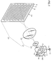
- the fluorescent screen 24 is formed such that the light, reflected from pixels of the reflecting layer of the light display shutter 181, precisely lands on and excites the corresponding fluorescent material through the optical system.
- the fluorescent screen 24 is formed by using a photolithography method, a slurry spin coating method, or a pressing method, all of which are used for forming a phosphor layer in conventional cathode-ray tubes or plasma display panels(PDPs).
- a sensitive resin pattern is first formed through the steps of cleaning a glass plate; depositing a photo sensitive resin consisting of acryl emulsion, pure water, a polymer of poly plastic alcohol, sodium dichromate, polymer of propylene oxide, and ethylene oxide, on an inner surface of the glass plate; and drying and developing the sensitive resin. Then, a black matrix layer for interrupting the exterior light and preventing color mixture is formed in a predetermined pattern by depositing black lead on the sensitive resin pattern and by removing the sensitive resin by etching using hydrogen peroxide.
- a first phosphor slurry including first phosphor particles, pure water, and poly vinyl alcohol is deposited on the black matrix layer, and the first phosphor is formed through the process of drying, exposure, developing, cleaning, and drying. Then, through the same process, second and third fluorescent layers are formed to make the fluorescent screen.
- the most efficient phosphors of red R, green G, and blue B are preferably used according to spectrum dispersion, the dispersion pattern being changed by the size of the picture screen and type of light.
- the red R fluorescent material having a wavelength within the range of 300nm to 450nm can be selected from the group consisting of Y 2 O 2 S:Eu 3+ , La 2 O 2 S:Eu 3+ , Y 2 O 3 :Eu 3+ , 3.5MgO ⁇ 0.5MgF 2 ⁇ GeO 2 :Mn 4+ , YVO 4 :Eu 3+ , SrY 2 S 4 :Eu 2+ , and K 5 Eu(WO 4 ) 4 ;
- the light shutter projector employing the inventive fluorescent screen 24 displays an image by passing an image, obtained when light having a wavelength in a predetermined range(e.g., ultraviolet rays) advances through the light display shutter assembly 18, through the second condensing lens 20 and the projecting lens 22 such that the light is radiated to correspond to the fluorescent material deposited on the fluorescent screen 24 in a predetermined pattern. That is, the image is displayed by means of exactly corresponding the pixels of the light display shutter 18 to the pixels of the fluorescent screen 24 by adjusting the second condensing lens 20 and the projecting lens 22.
- a predetermined range e.g., ultraviolet rays
- the second condensing lens 20 and the projecting lens 22 are preferably designed so as to excite only 90-95% of the size of each pixel in the fluorescent screen 24.
- the mask is preferably made of materials that are resistant to ultraviolet rays and absorb visible rays (e.g., steel or metal, or color plastic material), and is formed in a predetermined pattern having holes for the passage of light.
- a light shutter projector employing a fluorescent screen according to a second embodiment of the present invention.
- a fluorescent screen 28 is formed by a bundle of optical fibers 26 each operating as a pixel, the fluorescent screen 28 being deposited with a fluorescent material which irradiates by light, reflected from the light display shutter 181, at a predetermined wavelength.
- an optical system 31 comprises a second condensing lens 30 for converting the beams passing through the fluorescent screen 28 into radiated light, and an eye-lens 32 for magnifying or reducing the light concentrated through the second condensing lens 30.
- the optical fibers 26 are composed of a core 25 deposited with a fluorescent material, and a coating material 27 covering the core 25 to prevent color mixture of the fluorescent material deposited on the core 25.
- the optical fibers 26 forming the fluorescent screen 28 in the form of a bundle are preferably made of material having high transmissibility of ultraviolet rays, such as high grade fused silica or liquid glass, wherein the materials each having a different refractive index are respectively applied to the core 25 and the covering material 27.
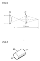
- the eye-lens 32 of the optical system 31 is an optical device that magnifies or reduces the image, formed on the fluorescent screen 28, to a ghost image keeping a visible range, wherein the eyelens 32 is preferably made of material which is suitable for light having a wavelength within the range of 400nm to 780nm.
- the eye-lens 32 is advantageously varied in its magnification by using one to three lenses which are slim, light, and small so as to select several magnifications or reductions according to the size of the picture screen, or by employing a changeable adapter or a zoom lens.
- the focal distance of the eye-lens 32 is obtained by dividing the minimum distance of distinct vision by the magnification of the eye-lens: since the minimum distance of distinct vision is 250mm, the formula can be expressed as: 250/magnification of the eye-lens.
- FIG. 7 there is shown a view illustrating a light shutter projector employing a fluorescent screen according to a third embodiment of the present invention.
- the difference of this embodiment from the second embodiment is that a fluorescent screen 34 layered with a fluorescent material is used.
- FIG. 8 there is shown a view illustrating a light shutter projector according to a fourth embodiment similar to the second embodiment.
- optical system 21 is disposed between a screen 36 formed by a bundle of optical fibers 26 and the beam splitter 16.
- a fluorescent screen in which a bundle of optical fibers are formed having fluorescent material deposited thereon, as it is possible for the size of the optical fibers to correspond to that of the pixels at a 1:1 ratio or at a magnified or reduced ratio, resolution and brightness can be improved, and because the fluorescent material is deposited only on the core of the fibers and the covering material covers the core, color mixture when emitting red, green, and blue light is prevented such that brightness is improved.
Landscapes
- Physics & Mathematics (AREA)
- Optics & Photonics (AREA)
- General Physics & Mathematics (AREA)
- Engineering & Computer Science (AREA)
- Multimedia (AREA)
- Signal Processing (AREA)
- Liquid Crystal (AREA)
- Projection Apparatus (AREA)
- Transforming Electric Information Into Light Information (AREA)
- Video Image Reproduction Devices For Color Tv Systems (AREA)
- Devices For Indicating Variable Information By Combining Individual Elements (AREA)
Applications Claiming Priority (2)
| Application Number | Priority Date | Filing Date | Title |
|---|---|---|---|
| KR9664633 | 1996-12-12 | ||
| KR1019960064633A KR100222602B1 (ko) | 1996-12-12 | 1996-12-12 | 형광막을 사용한 반사형 셔터 프로젝터 |
Publications (2)
| Publication Number | Publication Date |
|---|---|
| EP0851263A2 true EP0851263A2 (fr) | 1998-07-01 |
| EP0851263A3 EP0851263A3 (fr) | 1999-02-03 |
Family
ID=19487377
Family Applications (1)
| Application Number | Title | Priority Date | Filing Date |
|---|---|---|---|
| EP97118629A Withdrawn EP0851263A3 (fr) | 1996-12-12 | 1997-10-27 | Projecteur à valve de lumière avec un écran fluorescent |
Country Status (6)
| Country | Link |
|---|---|
| US (1) | US5957560A (fr) |
| EP (1) | EP0851263A3 (fr) |
| JP (1) | JPH10170881A (fr) |
| KR (1) | KR100222602B1 (fr) |
| CN (1) | CN1184949A (fr) |
| TW (1) | TW338108B (fr) |
Cited By (3)
| Publication number | Priority date | Publication date | Assignee | Title |
|---|---|---|---|---|
| WO2000017700A1 (fr) * | 1998-09-21 | 2000-03-30 | Screen Technology Limited | Montage optique pour ecrans plats |
| EP1681336A1 (fr) * | 2005-01-12 | 2006-07-19 | Samsung SDI Co., Ltd. | Phosphore et panneau d'affichage à plasma l'utilisant |
| US8147067B2 (en) | 2005-10-04 | 2012-04-03 | Koninklijke Philips Electronics N.V. | Laser projection system based on a luminescent screen |
Families Citing this family (27)
| Publication number | Priority date | Publication date | Assignee | Title |
|---|---|---|---|---|
| US6220730B1 (en) | 1998-07-01 | 2001-04-24 | Light & Sound Design, Ltd. | Illumination obscurement device |
| US6273589B1 (en) * | 1999-01-29 | 2001-08-14 | Agilent Technologies, Inc. | Solid state illumination source utilizing dichroic reflectors |
| EP1142033A1 (fr) | 1999-09-27 | 2001-10-10 | LumiLeds Lighting U.S., LLC | Dispositif a diode emetteur de lumiere produisant une lumiere blanche par totale conversion au phosphore |
| US6686691B1 (en) | 1999-09-27 | 2004-02-03 | Lumileds Lighting, U.S., Llc | Tri-color, white light LED lamps |
| US6696703B2 (en) | 1999-09-27 | 2004-02-24 | Lumileds Lighting U.S., Llc | Thin film phosphor-converted light emitting diode device |
| JP3984772B2 (ja) * | 2000-03-08 | 2007-10-03 | 株式会社日立製作所 | 液晶表示装置及び液晶表示装置用光源 |
| US6603258B1 (en) | 2000-04-24 | 2003-08-05 | Lumileds Lighting, U.S. Llc | Light emitting diode device that emits white light |
| JP5110744B2 (ja) | 2000-12-21 | 2012-12-26 | フィリップス ルミレッズ ライティング カンパニー リミテッド ライアビリティ カンパニー | 発光装置及びその製造方法 |
| US6844903B2 (en) * | 2001-04-04 | 2005-01-18 | Lumileds Lighting U.S., Llc | Blue backlight and phosphor layer for a color LCD |
| US6966655B2 (en) * | 2002-10-11 | 2005-11-22 | Sony Corporation | Projection type display device |
| CN1325989C (zh) * | 2003-05-13 | 2007-07-11 | 示创科技股份有限公司 | 使用铁电液晶调变器的液晶投影装置 |
| US7452082B2 (en) * | 2004-04-19 | 2008-11-18 | Superimaging, Inc. | Excitation light emission apparatus |
| US7976169B2 (en) * | 2003-05-14 | 2011-07-12 | Sun Innovations, Inc. | Waveguide display |
| US7090355B2 (en) * | 2003-05-19 | 2006-08-15 | Superimaging, Inc. | System and method for a transparent color image display utilizing fluorescence conversion of nano particles and molecules |
| US6987610B2 (en) * | 2003-10-23 | 2006-01-17 | Hewlett-Packard Development Company, L.P. | Projection screen |
| US7182467B2 (en) * | 2003-11-03 | 2007-02-27 | Superimaging, Inc. | Microstructures integrated into a transparent substrate which scatter incident light to display an image |
| CA2542793A1 (fr) * | 2003-11-03 | 2005-05-12 | Super-Imaging, Inc. | Matiere electroluminescente integree a un substrat sensiblement transparent |
| US7213923B2 (en) * | 2004-04-19 | 2007-05-08 | Superimaging, Inc. | Emission of visible light in response to absorption of excitation light |
| KR100638619B1 (ko) * | 2004-09-23 | 2006-10-26 | 삼성전기주식회사 | 파장변환용 형광체 혼합물과 이를 이용한 백색 발광장치 |
| WO2006094262A2 (fr) * | 2005-03-03 | 2006-09-08 | Superimaging, Inc. | Affichage |
| KR100924568B1 (ko) * | 2008-01-16 | 2009-10-30 | 김호기 | 투명한 녹색 형광막 제조방법 및 이를 적용한 형광등 |
| KR100924518B1 (ko) * | 2008-01-16 | 2009-11-02 | 김호기 | 투명한 적색 형광막 제조방법과 이를 적용한 형광등 |
| JP5962103B2 (ja) * | 2012-03-21 | 2016-08-03 | カシオ計算機株式会社 | 蛍光体デバイス、照明装置及びプロジェクタ装置 |
| CN103913934B (zh) * | 2013-01-01 | 2016-09-28 | 深圳市光峰光电技术有限公司 | 一种投影装置 |
| CN109477961B (zh) * | 2016-07-19 | 2021-02-26 | 麦克赛尔株式会社 | 投射型影像显示装置 |
| JP6880694B2 (ja) * | 2016-12-13 | 2021-06-02 | セイコーエプソン株式会社 | 照明装置及びプロジェクター |
| US12510814B1 (en) | 2021-12-23 | 2025-12-30 | The Invisible Pixel Inc. | Projection system and methods therefor |
Family Cites Families (9)
| Publication number | Priority date | Publication date | Assignee | Title |
|---|---|---|---|---|
| US3918803A (en) * | 1972-03-30 | 1975-11-11 | Harris Intertype Corp | Display of multicolor images using a screen with red, blue and green photoluminescent segments |
| US4872750A (en) * | 1982-07-14 | 1989-10-10 | Nec Home Electronics Ltd. | Image projection apparatus |
| US4714956A (en) * | 1982-09-24 | 1987-12-22 | Yin Ronald L | Color display apparatus and method therefor |
| US4737840A (en) * | 1983-07-31 | 1988-04-12 | Nec Home Electronics Ltd. | Color image projection apparatus with a screen including a shield plate, light-emitting layer and diffusion surface to expand viewing range of bright pictures |
| JP2914981B2 (ja) * | 1988-07-27 | 1999-07-05 | パイオニア株式会社 | 表示装置 |
| EP0391529B1 (fr) * | 1989-02-27 | 1995-05-03 | Texas Instruments Incorporated | Appareil pour système de vidéo numérisée |
| GB9020705D0 (en) * | 1990-09-22 | 1990-11-07 | Emi Plc Thorn | Imaging system |
| JPH05257110A (ja) * | 1992-03-13 | 1993-10-08 | Sharp Corp | 投射型液晶表示装置 |
| US5473396A (en) * | 1993-09-08 | 1995-12-05 | Matsushita Electric Industrial Co., Ltd. | Display apparatus and method of making the same |
-
1996
- 1996-12-12 KR KR1019960064633A patent/KR100222602B1/ko not_active Expired - Fee Related
-
1997
- 1997-06-03 JP JP9144389A patent/JPH10170881A/ja active Pending
- 1997-10-09 TW TW086114899A patent/TW338108B/zh active
- 1997-10-20 US US08/954,268 patent/US5957560A/en not_active Expired - Fee Related
- 1997-10-27 EP EP97118629A patent/EP0851263A3/fr not_active Withdrawn
- 1997-11-14 CN CN97122272A patent/CN1184949A/zh active Pending
Cited By (3)
| Publication number | Priority date | Publication date | Assignee | Title |
|---|---|---|---|---|
| WO2000017700A1 (fr) * | 1998-09-21 | 2000-03-30 | Screen Technology Limited | Montage optique pour ecrans plats |
| EP1681336A1 (fr) * | 2005-01-12 | 2006-07-19 | Samsung SDI Co., Ltd. | Phosphore et panneau d'affichage à plasma l'utilisant |
| US8147067B2 (en) | 2005-10-04 | 2012-04-03 | Koninklijke Philips Electronics N.V. | Laser projection system based on a luminescent screen |
Also Published As
| Publication number | Publication date |
|---|---|
| JPH10170881A (ja) | 1998-06-26 |
| KR100222602B1 (ko) | 1999-10-01 |
| TW338108B (en) | 1998-08-11 |
| KR19980046310A (ko) | 1998-09-15 |
| EP0851263A3 (fr) | 1999-02-03 |
| US5957560A (en) | 1999-09-28 |
| MX9708224A (es) | 1998-06-30 |
| CN1184949A (zh) | 1998-06-17 |
Similar Documents
| Publication | Publication Date | Title |
|---|---|---|
| US5957560A (en) | Light shutter projector with a fluorescent screen | |
| CN100411432C (zh) | 平板显示器 | |
| CN1265243C (zh) | 背投式显示装置及应用于它的透射式显示屏 | |
| KR19980046311A (ko) | 형광막 프로젝터 | |
| KR100803586B1 (ko) | 프로젝션 텔레비전의 휘도 개선장치 | |
| JPH0313794B2 (fr) | ||
| KR100292356B1 (ko) | 배면투사형액정프로젝트장치 | |
| CN111999870B (zh) | 用于图像投影的变焦镜头及图像投影装置 | |
| US5662402A (en) | Projector with detachable liquid crystal panel | |
| KR20020043666A (ko) | 액정 프로젝터의 광학계 | |
| JP2001228809A (ja) | ディスプレイ装置 | |
| JP2009151078A (ja) | 投影光学系および画像投影装置 | |
| JP3163648B2 (ja) | 投射型表示装置 | |
| MXPA97008224A (en) | Light shutter projector with a fluoresce screen | |
| JP2004302478A (ja) | アクティブマトリックス型表示パネル、ビューファインダ、及び投射型表示装置 | |
| KR200241244Y1 (ko) | 전면투사형 액정 투사장치 | |
| JPH08304606A (ja) | 反射光吸収板および表示パネルとそれを用いた表示装置 | |
| JPH03266584A (ja) | 液晶プロジェクタ | |
| JP2007212716A (ja) | 画像表示装置およびプロジェクタ | |
| JP2000081668A (ja) | 背面投写型表示装置 | |
| JPH01307790A (ja) | 透過形カラー画像表示装置の照明装置 | |
| EP0615388A2 (fr) | Appareil pour la projection optique en couleur avec affichage à cristaux liquides | |
| JP2007218946A (ja) | 画像表示装置およびプロジェクタ | |
| JP2001215615A (ja) | 投写型表示装置 | |
| JP2006133760A (ja) | レンチキュラーレンズシーツとその製造方法 |
Legal Events
| Date | Code | Title | Description |
|---|---|---|---|
| PUAI | Public reference made under article 153(3) epc to a published international application that has entered the european phase |
Free format text: ORIGINAL CODE: 0009012 |
|
| AK | Designated contracting states |
Kind code of ref document: A2 Designated state(s): DE FR GB |
|
| AX | Request for extension of the european patent |
Free format text: AL;LT;LV;RO;SI |
|
| PUAL | Search report despatched |
Free format text: ORIGINAL CODE: 0009013 |
|
| AK | Designated contracting states |
Kind code of ref document: A3 Designated state(s): AT BE CH DE DK ES FI FR GB GR IE IT LI LU MC NL PT SE |
|
| AX | Request for extension of the european patent |
Free format text: AL;LT;LV;RO;SI |
|
| 17P | Request for examination filed |
Effective date: 19990506 |
|
| AKX | Designation fees paid |
Free format text: DE FR GB |
|
| 17Q | First examination report despatched |
Effective date: 20020926 |
|
| STAA | Information on the status of an ep patent application or granted ep patent |
Free format text: STATUS: THE APPLICATION IS DEEMED TO BE WITHDRAWN |
|
| 18D | Application deemed to be withdrawn |
Effective date: 20030207 |