EP0851448A1 - Unité de commande configurable pour commander des dispositifs électroniques - Google Patents
Unité de commande configurable pour commander des dispositifs électroniques Download PDFInfo
- Publication number
- EP0851448A1 EP0851448A1 EP96120883A EP96120883A EP0851448A1 EP 0851448 A1 EP0851448 A1 EP 0851448A1 EP 96120883 A EP96120883 A EP 96120883A EP 96120883 A EP96120883 A EP 96120883A EP 0851448 A1 EP0851448 A1 EP 0851448A1
- Authority
- EP
- European Patent Office
- Prior art keywords
- microcontroller
- control
- operating unit
- unit according
- pressure
- Prior art date
- Legal status (The legal status is an assumption and is not a legal conclusion. Google has not performed a legal analysis and makes no representation as to the accuracy of the status listed.)
- Granted
Links
- 230000001419 dependent effect Effects 0.000 claims abstract description 7
- 239000011888 foil Substances 0.000 abstract description 6
- 230000006870 function Effects 0.000 description 38
- 239000010410 layer Substances 0.000 description 36
- 238000013461 design Methods 0.000 description 26
- 239000010408 film Substances 0.000 description 26
- 230000005540 biological transmission Effects 0.000 description 11
- 238000003825 pressing Methods 0.000 description 11
- 238000006243 chemical reaction Methods 0.000 description 9
- 238000004026 adhesive bonding Methods 0.000 description 4
- 238000010276 construction Methods 0.000 description 4
- 238000006073 displacement reaction Methods 0.000 description 4
- 238000011156 evaluation Methods 0.000 description 4
- 238000012423 maintenance Methods 0.000 description 4
- 238000005299 abrasion Methods 0.000 description 3
- 230000008859 change Effects 0.000 description 3
- 230000007246 mechanism Effects 0.000 description 3
- 238000000034 method Methods 0.000 description 3
- 239000011241 protective layer Substances 0.000 description 3
- 230000004304 visual acuity Effects 0.000 description 3
- 230000006978 adaptation Effects 0.000 description 2
- 238000004364 calculation method Methods 0.000 description 2
- 238000011960 computer-aided design Methods 0.000 description 2
- 238000011109 contamination Methods 0.000 description 2
- 238000009826 distribution Methods 0.000 description 2
- 238000005516 engineering process Methods 0.000 description 2
- 230000003203 everyday effect Effects 0.000 description 2
- 238000004519 manufacturing process Methods 0.000 description 2
- 238000012544 monitoring process Methods 0.000 description 2
- 238000007781 pre-processing Methods 0.000 description 2
- 230000035945 sensitivity Effects 0.000 description 2
- 238000012360 testing method Methods 0.000 description 2
- 230000001960 triggered effect Effects 0.000 description 2
- 241000577979 Peromyscus spicilegus Species 0.000 description 1
- 230000003213 activating effect Effects 0.000 description 1
- 230000004913 activation Effects 0.000 description 1
- 238000013459 approach Methods 0.000 description 1
- 230000006399 behavior Effects 0.000 description 1
- 230000008901 benefit Effects 0.000 description 1
- 230000002457 bidirectional effect Effects 0.000 description 1
- 239000011248 coating agent Substances 0.000 description 1
- 238000000576 coating method Methods 0.000 description 1
- 238000004883 computer application Methods 0.000 description 1
- 238000012790 confirmation Methods 0.000 description 1
- 238000005520 cutting process Methods 0.000 description 1
- 230000000694 effects Effects 0.000 description 1
- 230000007257 malfunction Effects 0.000 description 1
- 238000003801 milling Methods 0.000 description 1
- 230000003287 optical effect Effects 0.000 description 1
- 229920003023 plastic Polymers 0.000 description 1
- 239000002985 plastic film Substances 0.000 description 1
- 238000007639 printing Methods 0.000 description 1
- 230000008569 process Effects 0.000 description 1
- 230000008672 reprogramming Effects 0.000 description 1
- 238000003860 storage Methods 0.000 description 1
- 239000010409 thin film Substances 0.000 description 1
- 238000012549 training Methods 0.000 description 1
- 239000012780 transparent material Substances 0.000 description 1
- 238000012800 visualization Methods 0.000 description 1
Images

Classifications
-
- H—ELECTRICITY
- H01—ELECTRIC ELEMENTS
- H01H—ELECTRIC SWITCHES; RELAYS; SELECTORS; EMERGENCY PROTECTIVE DEVICES
- H01H13/00—Switches having rectilinearly-movable operating part or parts adapted for pushing or pulling in one direction only, e.g. push-button switch
- H01H13/70—Switches having rectilinearly-movable operating part or parts adapted for pushing or pulling in one direction only, e.g. push-button switch having a plurality of operating members associated with different sets of contacts, e.g. keyboard
- H01H13/78—Switches having rectilinearly-movable operating part or parts adapted for pushing or pulling in one direction only, e.g. push-button switch having a plurality of operating members associated with different sets of contacts, e.g. keyboard characterised by the contacts or the contact sites
- H01H13/785—Switches having rectilinearly-movable operating part or parts adapted for pushing or pulling in one direction only, e.g. push-button switch having a plurality of operating members associated with different sets of contacts, e.g. keyboard characterised by the contacts or the contact sites characterised by the material of the contacts, e.g. conductive polymers
-
- H—ELECTRICITY
- H01—ELECTRIC ELEMENTS
- H01H—ELECTRIC SWITCHES; RELAYS; SELECTORS; EMERGENCY PROTECTIVE DEVICES
- H01H13/00—Switches having rectilinearly-movable operating part or parts adapted for pushing or pulling in one direction only, e.g. push-button switch
- H01H13/70—Switches having rectilinearly-movable operating part or parts adapted for pushing or pulling in one direction only, e.g. push-button switch having a plurality of operating members associated with different sets of contacts, e.g. keyboard
- H01H13/702—Switches having rectilinearly-movable operating part or parts adapted for pushing or pulling in one direction only, e.g. push-button switch having a plurality of operating members associated with different sets of contacts, e.g. keyboard with contacts carried by or formed from layers in a multilayer structure, e.g. membrane switches
-
- H—ELECTRICITY
- H01—ELECTRIC ELEMENTS
- H01H—ELECTRIC SWITCHES; RELAYS; SELECTORS; EMERGENCY PROTECTIVE DEVICES
- H01H2201/00—Contacts
- H01H2201/022—Material
- H01H2201/032—Conductive polymer; Rubber
- H01H2201/036—Variable resistance
-
- H—ELECTRICITY
- H01—ELECTRIC ELEMENTS
- H01H—ELECTRIC SWITCHES; RELAYS; SELECTORS; EMERGENCY PROTECTIVE DEVICES
- H01H2219/00—Legends
- H01H2219/002—Legends replaceable; adaptable
Definitions
- the invention relates to an operating unit for controlling electronic Equipment.
- PC-controlled device arrangements in which, however, the PC at the same time other tasks within the executes application programs running on it. In this sense is a PC not to be understood as a pure operating unit.
- a characteristic feature of all known operating units is therefore that they are for a larger amount of functionally similar devices or Device arrangements are designed and it is assumed that the average operator the user interface defined in advance and accepted their design without requests for changes.
- Handheld remote controls data transmission via infrared or wired
- All Manual remote controls are at least for a certain type of device similar, sometimes even from the basic concept for devices different types' suitable. In this case, the existing ones Control elements (mostly buttons) only with other functions and the graphic design or the geometric dimensions changed slightly.
- Handheld remote controls for a device type for example a specific one VCRs, a certain television, a certain radio
- As many control elements are physically similar. The user generally has does not affect the configuration of the stored functions Design of the user interface or the control unit itself.
- Self-learning remote controls (data transmission mostly by infrared) are characterized by many physically identical control elements, which can learn certain bit sequences as control sequences.
- the design freedom of the user is based on the arrangement of commands for individual control elements and also on relatively simple commands A", Out", +1 ", -1 ".
- Table remote controls (data transmission via infrared or wired) are identical to those of Handheld remote controls, however, generally have larger dimensions Control unit as well as its control elements. Here are mostly a specified number of pre-assembled switches, controllers, buttons and The like retrospectively with certain control commands wired. There are limited configuration options that however not by the user himself, but by appropriately trained people People must be made. A free design of the Switch shapes and the arrangement of the controls is simple and Generally possible only in advance, then only with considerable Effort or no longer to be carried out.
- LCD displays built into control devices provide a relatively flexible Arrangement of controls, related functions and the shape.
- control unit In principle, however, they are available according to the current state of the art standing advertisements at a low price either only black and white versions, or limited to very small dimensions. This too The type of control unit is generally not for individualization designed and has only a very low point resolution for cost reasons on. In order to remain legible for the user, they must be relatively large Symbols or controls are used, or they fit relatively few controls on the display.
- Digitizing tablets continue to be used in connection with computer applications
- Visualization devices such as LCD displays or Cathode ray screens are known. Such trays capture the relative Coordinates of a corresponding pen and set its movements in one Display device on the respective screen (e.g. mouse pointer).
- the underlying computer ensures implementation in each case desired commands.
- Areas of application are above all the simple one Control of software programs or the creation of graphics within computer-aided design (CAD).
- CAD computer-aided design
- the respective one Control program or the appearance of the user interface in the generally not intended for individualization, so changes either not at all or only to a very limited extent (e.g. selection of functions and arrangement) can be made.
- the object of the invention is to provide a manual control unit which a custom design of Control elements for any electronic devices or Device arrangements guaranteed.
- the control unit should be without significant design changes for each type of device or Device arrangement may be suitable.
- an operating unit is provided to control at least one electronic device, characterized by a pressure-sensitive film (10) with areas which symbolic keys are assigned and the pressure point dependent Coordinate currents supplies, and by a microcontroller (9), the converts pressure point dependent coordinate streams into coordinate values with compares stored coordinate values and depending on the Comparison result at least one of the respective coordinate values assigned command to control the at least one electronic Device generated (claim 1).
- the design of the controls is not geometric, graphic or functional restrictions to be functional and intuitive Allow operator guidance.
- the coordinates are Cartesian coordinates, preferably X / Y coordinates (Claim 2).
- the symbolic buttons are on one above the pressure sensitive one Foil lying carrier layer (claim 4).
- This backing layer can for example as printed paper or printed, thin film. In principle, however, any other printable carrier medium is also suitable. There are changes to the visible design of the symbolic buttons subsequently possible by simply exchanging the carrier layer (claim 5).
- buttons can be directly on the are pressure-sensitive layer (claim 3). In this case, then however, the desired simple, subsequent reconfiguration option difficult, because with each design change of the control elements a new one pressure sensitive film must be mounted.
- the graphic layout created is optionally printed on paper using standard printers, Foil, the pressure-sensitive foil itself or any other suitable one transferable printable information carrier. That way ensured that the spatial distribution of the controls on the pressure sensitive film is identical to that on the printed layer. In addition, visible marks applied to both layers ensure that Final assembly for the necessary lateral match.
- a third layer can optionally be arranged.
- the Standard foils generally have such a high inner Resolution on that incorrect operation due to the above effects can be excluded.
- the microcontroller has an interface for reading in Coordinate values and / or commands assigned by the coordinate values (Claim 6).
- This conversion rule from X / Y coordinates to Operating states, control commands or control sequences of those to be controlled Device arrangements are due to the desired, easy changeability the control unit expediently in a microcontroller stored in electrically programmable memory.
- Such memory modules are available as standard in various storage depths and Technology versions available.
- the control command is either, depending on the version of the control unit wired or wireless to the Device arrangement forwarded.
- the modular arrangement of the Evaluation electronics of the control unit (microcontroller, programmable Memory, interface modules wired, interface modules wireless, device-specific converter) will adapt to any type of devices or device arrangements as well as their analog / digital Data formats and command syntax reached.
- microcontroller is the same between at least two Commands assigned to coordinate values can be switched (claim 8). Thereby is achieved that different with just a single control unit User interfaces are available.
- the decoupling of the representation of control elements on a printed Area for the human eye and its electronic replica on a second, pressure sensitive layer requires a high lateral Agreement between both layers to prevent malfunction during the Exclude operation.
- the Layers will therefore first include the graphical representation of the control elements made a simple graphics program.
- all controls will have the desired functions or - sequences (e.g. as part of a function database) and then using a conversion routine from the graphic layout and the corresponding functions the corresponding program of the Microcontroller generated.
- the conversion routine of the device functions in Microcontroller commands are the only device-dependent part for creating the Operating unit, as it may have special features typical of the device incorporated into functions, function sequences and / or the command syntax Need to become.
- a microcontroller and related technology ensures that flexible to different requirements of Device arrangements with regard to functions and command syntax are reacted to can.
- a wired or wireless transmission can be configured.
- a local Configuration via e.g. serial or parallel computer interfaces be provided, or even the configuration remotely via e.g. ISDN interfaces or other WAN connections.
- control elements per room unit Due to the analog coding of the X / Y coordinates in the form of currents in the X or Y direction, very high resolutions of control elements per room unit are possible. Theoretically, one control element can be represented per I x -I y pair. The resolution per unit of space is determined on the one hand by the accuracy of the pressure-sensitive film, and on the other hand by the resolving power of the downstream evaluation unit. Overall, there is a resolving power which is far above the comparable control units realized according to the current state of the art.
- the microcontroller can all coordinate streams from each symbolic button corresponding area originate from that button assign associated coordinate values (claim 7). Since this is on the pressure-sensitive layer with the generation of total currents in X or Y direction is equivalent, this results in a certain blurring of the Pressure point information. By forming the focus of the Pressure point information in the evaluation unit can have slight deviations are compensated by the target pressure point specified by the control element, without there being any operating errors. The concept presented offers in addition, therefore, a certain fault tolerance towards incorrect operation.
- Another advantage of the invention is that of conventional ones Control units increased pressure sensitivity.
- a simple one is enough Pressure on the pressure sensitive area to the desired control command or trigger the control sequence.
- Sensitivity is also a function here both the pressure-sensitive film and the resolving power of the downstream evaluation unit.
- All operations can be done both locally and from the Distance over e.g. Make ISDN, LAN or WAN connections, if an appropriately configured control unit was used.
- a Such remote control option relates to the one hand Operations for device control, as well as for remote loading new functions or function sequences into the microcontroller as also changes to existing functions or sequences.
- microcontroller has an input for the current state of electronic signals representing electronic device (claim 9).
- an acoustic signal generator (claim 10). This provides the user with a valuable control option.
- control unit Due to the modular arrangement of the control unit from modules for Microcontroller, programmable memory, IR transmission or wired, output interfaces, input interfaces, converters for certain command syntax or data formats of device arrangements is the Control unit for a wide variety of needs and requirements configurable. In particular, this concept is a high one Future security achieved with new device arrangements.
- FIG An arrangement of the various components is shown schematically in FIG represented an operating unit according to the invention.
- a first Housing (upper) part 2 is a pressure-sensitive film 10 inserted through corresponding recesses in housing part 2 against displacements in X and Y direction is secured.
- a pressure-sensitive film 10 inserted through corresponding recesses in housing part 2 against displacements in X and Y direction is secured.
- other than that drawn mechanism prevent the film 10 from shifting, e.g. mechanical fastening by gluing the film 10 to the bottom of the Housing part 2 or fixing by means of recesses in the film 10, by the corresponding counter pieces of the housing part 2 are guided.
- the Functionality of the control unit is the way of fixing the Slide 10 irrelevant.
- Another layer 8 is applied over the pressure-sensitive film 10 contains the controls visible to the operator.
- This layer 8 can e.g. be designed as printed paper or printed film.
- layer 8 is secured against displacement, so that the lateral Agreement between the two layers 8 and 10 is guaranteed.
- mutual displacement can also can be achieved by gluing both layers together. The important thing is that a shifting of the security mechanism chosen pressure-sensitive film 10 against the layer 8 is permanently prevented.
- layer 8 can be omitted. In this case however, if desired changes to the graphic appearance of the Controls immediately replace the pressure sensitive film 10 necessary.
- a third layer 6 can be arranged over it.
- This Layer preferably consists of a thin, transparent material high mechanical abrasion resistance.
- the protective layer 6 also be directly connected to layer 8, e.g. through an additional applied coating.
- housing part 4 In addition to the upper housing part 2, there is a lower housing part 4, which generally from its geometric shape to that of Housing part 2 corresponds and how the housing part 2 over Fastening options of both housing halves together. Such Mutual fastening options are depending on the requirements of the Operating unit either as screw connections, gluing or Welds carried out. Any other form of attachment of the two However, housing halves are also conceivable.
- the electronic components 12 with all external connections 14 are accommodated.
- the electrical components are attached using standard means of techniques available today, e.g. Screw connections, gluing or precise clamping, however, can also done by any other type of attachment.
- the division into two housing halves 4 and 2 is not mandatory Prerequisite for the functionality of the invention Operating units. Operating units can also consist of only one Housing part or more than two parts exist.
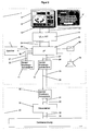
- FIG. 2 A complete device arrangement is shown in FIG. 2.
- a cover and at the same time protective layer opposite Contamination and mechanical influences are served by a layer 8 arranged thin, transparent plastic film 6.
- the pressure sensitive film 10 is attached such that the in the memory 7 stored conversion table from X / Y coordinates to control commands exactly the visible arrangement of the controls on the printed paper 8 corresponds. All three layers 6, 8 and 10 are by inserting them into corresponding ones mechanical cutouts of the control unit against lateral displacement protected.
- the visible arrangement of the controls on the printed Paper 8 and the coding of the not visible to the operator Control elements within layer 10 are thus permanently with one another connected.
- preprocessing unit 4 When pressure is applied to any point on the user interface 8, currents I x and I y 22 are generated in the pressure-sensitive film 10 and forwarded to a preprocessing unit 4.
- the task of the preprocessing unit 4 is to calculate absolute X and Y coordinates 24 from the currents I x / I y 22 generated or to convert these coordinates into a signal form suitable for the microcontroller 9.
- the microcontroller's own program ensures at sufficiently frequent time intervals that the signals 24 present at its inputs are recorded and further processed internally.
- the microcontroller 9 With the help of the X / Y coordinates 24 and those in the memory 7 (e.g. internal RAM, EEPROM or Flash EPROM) stored conversion table of X / Y coordinates In control information 34, the microcontroller 9 generates the Operator expected control instructions 26. Such instructions can both depend on control instructions 26 already executed as well to be memoryless. It is the task of the microcontroller 9 current Tax information 34 in the context of already done or too to manage and generate active control instructions 26.
- the memory 7 e.g. internal RAM, EEPROM or Flash EPROM
- All control instructions 26 are through an interface module 12 in the data format required for the respective transmission link or required optical / electrical signals 28 implemented and to the transmitter / receiver module 16 of the video conference system 20 sent.
- Task of Transceiver module 16 is the conversion of the input signals 28 into the data formats and signals 30 expected by the central control unit 18.
- In of the control unit 18 are those of the transmission and reception module 16 generated signals 30 recorded and depending on the type of Control commands to be executed 30 signals 32 to the respective device within the video conference system 20 sent.
- As a transmission medium for the Signals 32 are either separate data lines or for each device Bus systems used.
- those of the respective device of the video conference system 20 generated feedback 33 received in the central control unit 18 and evaluated. Evaluated feedback is given in instructions 31 implemented and via the transmit / receive modules 16 and 12 to the Microcontroller 9 forwarded.
- an acoustic signal is generated with the aid of a loudspeaker 14.
- the acoustic signals differed depending on whether Control elements pressed and thus control instructions 26 were generated or whether there is a position on the user interface that is not occupied by controls was pressed. The same applies to feedback 33 or 27.
- the operator receives immediate feedback on the success or failure of the control processes triggered by him.
- All control information 34 stored in the memory 7 is via one additional transmission and reception module 11 also from a distance can be generated. Because of the bidirectional transmission, this is on the one hand Remote control of the control unit and thus also the video conference system possible, on the other hand can be sent via the microcontroller Control instructions 37 a monitoring of the executed control instructions be done remotely. In both cases, they are very simple Diagnoses, test runs and other maintenance work can be carried out without maintenance personnel should necessarily be available on site.
- the same send and receive interface is also available the reconfiguration of the conversion tables in the memory 7 possible, so that the expansion of the user interface with new functions, others Distributions of the controls on the pressure sensitive surface 10 or other changes can be made remotely.
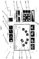
- Figure 3 shows an example of a possible design of the user interface represents how it could be carried out according to the invention.
- the graphic layout is for this purpose printed on a layer 42, which is printed as described in FIG Paper, printed film or the pressure sensitive film can be.
- the individual control elements are in the form of three-dimensional Switches (e.g. switch number 46, 48, 414, 416, 418, etc.), or even as surface elements such as switches number 420 and 422
- switches number 420 and 422 To show possibilities of the embodiment according to the invention are different types of switches described below:
- Control element 44 serves as in the example shown Initialization switch with which the device arrangement in a certain Basic state can be driven.
- Initialization switch with which the device arrangement in a certain Basic state can be driven.
- this Control element is thus a series of commands via the microcontroller or executed command sequences for which in control units after the State of the art the activation of a large number of individual switches, controllers and similar is necessary.
- the control elements 46 and 48 each serve as on and off switches certain operating states without knowing the current state force. In this case, pressing switch 46 will always do that Microphone switched on, while pressing switch 48 always that Microphone is switched off, regardless of the previous state. Of the In these cases, the microcontroller only needs a single control command generate (memoryless control).
- Control element 410 is closed in the same manner as control element 44 understand: by pressing this control element situation or company-specific basic settings are stored, for example on the positions and image detail of the cameras, the basic volume of the Speakers and similar settings.
- each control a variety of commands linked by the Microcontrollers are processed one after the other.
- that can graphical layout of the control element in terms of color and geometry Design correspond to the respective company logo, so that a very intuitive Operating possibility is created.
- Control 414 serves as another example of triggering multiple microcontroller commands by a single control. Such functions are generally simulated in control units according to the prior art by various control elements. By pressing the control element 414, the command sequences in the microcontroller Move camera in the X direction "as well Move camera in Y direction "triggered as long as control element 414 remains pressed.
- the combination of controls 416 and 418 shows that the function certain controls are programmable from the outside and also from depending on the history of the previously pressed controls: became the Example move the camera to a certain position and should move to that position can be saved permanently by pressing the combination control 418 and then control 416 this camera position under the respective control element 416 filed.
- the camera is independent of its current position automatically moved to the previously saved position.
- the microcontroller has the difference of the desired position with the current position compare and generate the corresponding control commands.
- Control element 420 is an example of the arrangement of a one-dimensional potentiometer on the active surface of the pressure-sensitive film: by pressing the surface between the two end points of the potentiometer symbol, the corresponding zoom position of the camera is approached directly in the example.
- the operator can directly determine the desired zoom end point without the sequential pressing of a Plus zoom "or Minus-Zoom "symbol would be necessary.
- the size of the potentiometer range on the pressure-sensitive film can be used to specify the desired resolution.
- Control element 422 serves as an example of a two-dimensional potentiometer. Each point within control 422 serves as the desired one Approach position of the camera. By pressing the respective point within the the associated X / Y coordinate becomes the bold framed total area of the control element 422 calculated and by the microcontroller in absolute coordinates of the graphically reproduced space. Using this illustration rule the microcontroller must issue the appropriate control commands for the camera generate and then move them to the desired position. How through The symbols 424, 426, 428 and 430 indicated, are all special features of a room can be displayed and thus a very intuitive operation of the Device arrangement, here especially the camera positioning possible.
Landscapes
- Position Input By Displaying (AREA)
- Push-Button Switches (AREA)
- Programmable Controllers (AREA)
- User Interface Of Digital Computer (AREA)
- Selective Calling Equipment (AREA)
- Circuits Of Receivers In General (AREA)
- Electrotherapy Devices (AREA)
Priority Applications (4)
| Application Number | Priority Date | Filing Date | Title |
|---|---|---|---|
| ES96120883T ES2145965T3 (es) | 1996-12-27 | 1996-12-27 | Unidad de mando para el control de aparatos electronicos. |
| EP96120883A EP0851448B2 (fr) | 1996-12-27 | 1996-12-27 | Unité de commande configurable pour commander des dispositifs électroniques |
| DE59604552T DE59604552D1 (de) | 1996-12-27 | 1996-12-27 | Gestaltbare Bedienungseinheit zur Steuerung elektronischer Geräte |
| AT96120883T ATE190170T1 (de) | 1996-12-27 | 1996-12-27 | Gestaltbare bedienungseinheit zur steuerung elektronischer geräte |
Applications Claiming Priority (1)
| Application Number | Priority Date | Filing Date | Title |
|---|---|---|---|
| EP96120883A EP0851448B2 (fr) | 1996-12-27 | 1996-12-27 | Unité de commande configurable pour commander des dispositifs électroniques |
Publications (3)
| Publication Number | Publication Date |
|---|---|
| EP0851448A1 true EP0851448A1 (fr) | 1998-07-01 |
| EP0851448B1 EP0851448B1 (fr) | 2000-03-01 |
| EP0851448B2 EP0851448B2 (fr) | 2004-11-10 |
Family
ID=8223560
Family Applications (1)
| Application Number | Title | Priority Date | Filing Date |
|---|---|---|---|
| EP96120883A Expired - Lifetime EP0851448B2 (fr) | 1996-12-27 | 1996-12-27 | Unité de commande configurable pour commander des dispositifs électroniques |
Country Status (4)
| Country | Link |
|---|---|
| EP (1) | EP0851448B2 (fr) |
| AT (1) | ATE190170T1 (fr) |
| DE (1) | DE59604552D1 (fr) |
| ES (1) | ES2145965T3 (fr) |
Cited By (2)
| Publication number | Priority date | Publication date | Assignee | Title |
|---|---|---|---|---|
| DE10158551A1 (de) * | 2001-11-29 | 2003-06-26 | Guenter Reichensperger | Fernbedienung für eine Videokonferenz-Anlage sowie Verfahren zur Konfektionierung der Fernbedienung |
| US8144036B2 (en) | 2007-02-08 | 2012-03-27 | Lear Corporation | Switch system |
Citations (2)
| Publication number | Priority date | Publication date | Assignee | Title |
|---|---|---|---|---|
| FR2570849A1 (fr) * | 1984-09-24 | 1986-03-28 | Paret Henriette | Dispositif pour la detection, la saisie et la transmission des coordonnees x, y definissant le positionnement d'un point sur un ecran graphique et la selection automatique de fonctions specifiques |
| US5283558A (en) * | 1989-10-16 | 1994-02-01 | Chan James K | Low-cost devices for touch control |
Family Cites Families (3)
| Publication number | Priority date | Publication date | Assignee | Title |
|---|---|---|---|---|
| DE3142861A1 (de) † | 1981-10-29 | 1983-05-19 | Hajek Jan Dipl Ing | Elektronische tastatur |
| NL8302091A (nl) † | 1983-06-13 | 1985-01-02 | Philips Nv | Afstandsbedieningssysteem bevattende een bedieningsorgaan voorzien van een afbeeldingsscherm en daarmee gekoppelde positiebepalingsmiddelen. |
| US4746919A (en) † | 1986-03-28 | 1988-05-24 | Rca Licensing Corporation | Remote control system with key function display provisions |
-
1996
- 1996-12-27 ES ES96120883T patent/ES2145965T3/es not_active Expired - Lifetime
- 1996-12-27 DE DE59604552T patent/DE59604552D1/de not_active Expired - Fee Related
- 1996-12-27 AT AT96120883T patent/ATE190170T1/de not_active IP Right Cessation
- 1996-12-27 EP EP96120883A patent/EP0851448B2/fr not_active Expired - Lifetime
Patent Citations (2)
| Publication number | Priority date | Publication date | Assignee | Title |
|---|---|---|---|---|
| FR2570849A1 (fr) * | 1984-09-24 | 1986-03-28 | Paret Henriette | Dispositif pour la detection, la saisie et la transmission des coordonnees x, y definissant le positionnement d'un point sur un ecran graphique et la selection automatique de fonctions specifiques |
| US5283558A (en) * | 1989-10-16 | 1994-02-01 | Chan James K | Low-cost devices for touch control |
Cited By (3)
| Publication number | Priority date | Publication date | Assignee | Title |
|---|---|---|---|---|
| DE10158551A1 (de) * | 2001-11-29 | 2003-06-26 | Guenter Reichensperger | Fernbedienung für eine Videokonferenz-Anlage sowie Verfahren zur Konfektionierung der Fernbedienung |
| DE10158551B4 (de) * | 2001-11-29 | 2005-11-03 | Reichensperger, Günter | Fernbedienung für eine Videokonferenz-Anlage sowie Verfahren zur Konfektionierung der Fernbedienung |
| US8144036B2 (en) | 2007-02-08 | 2012-03-27 | Lear Corporation | Switch system |
Also Published As
| Publication number | Publication date |
|---|---|
| ATE190170T1 (de) | 2000-03-15 |
| EP0851448B2 (fr) | 2004-11-10 |
| DE59604552D1 (de) | 2000-04-06 |
| EP0851448B1 (fr) | 2000-03-01 |
| ES2145965T3 (es) | 2000-07-16 |
Similar Documents
| Publication | Publication Date | Title |
|---|---|---|
| EP1431866B1 (fr) | Appareil HMI avec un écran tactil de type optique | |
| DE60011770T2 (de) | Verfahren und vorrichtung zur navigation mit verschiebbaren kreuzungspunkten in einer benutzerschnittstelle | |
| EP3947242B1 (fr) | Procédé et dispositif pour commander une machine de transbordement de matériaux et/ou un engin de construction | |
| DE102017124552B4 (de) | Mit mobilgerät verbundenes not-halt-system | |
| EP2994020B1 (fr) | Commande manuelle pour un mécanisme d'entrainement de meuble à moteur électrique, procédé de détection d'un actionnement d'une commande manuelle et mécanisme d'entrainement de meuble | |
| DE19937463B4 (de) | Verfahren zum Betrieb einer Multifunktionsbedieneinrichtung bei Kraftfahrzeugen, sowie Multifunktionsbedieneinrichtung selbst | |
| EP1513056A2 (fr) | Appareil d'entrée 3 D à écran tactile intégré | |
| EP2828056A1 (fr) | Dispositif et procédé destinés à commander une machine équipée d'un appareil de manipulation | |
| EP3140083A1 (fr) | Dispositif de services et système de commande | |
| EP2750335A2 (fr) | Appareil d'interaction enfichable | |
| EP2306648B1 (fr) | Transmission de données duplex par appareil électronique portatif et appareil de terrain | |
| EP0284007A2 (fr) | Dispositif pour introduire des données dans une machine à imprimer | |
| EP0851448B1 (fr) | Unité de commande configurable pour commander des dispositifs électroniques | |
| EP1973131B1 (fr) | Interrupteur multiple, en particulier pour aveugles | |
| DE20117645U1 (de) | Bedieneinrichtung | |
| DE69225607T2 (de) | Vorrichtung zur vereinfachung des gebrauchs eines informationssystems | |
| EP3412118A1 (fr) | Pupitre de commande de lumière à moyen de réglage rotatif et procédé pour faire fonctionner un pupitre de commande de lumière à moyen de réglage rotatif | |
| EP1437642A2 (fr) | Appareil de contrôle-commande ayant un clavier à entrée rapide | |
| DE102008007194A1 (de) | Schaltersystem | |
| EP1973387B1 (fr) | Commutateur à plusieurs voies dans un réseau de construction | |
| EP2697702A1 (fr) | Dispositif et procédé de commande gestuelle d'un écran de visualisation dans une salle de contrôle | |
| DE3906088A1 (de) | Eingabegeraet zur eingabe von befehlen in eine datenverarbeitungsanlage | |
| EP0921360B1 (fr) | Régulateur | |
| EP3657286A1 (fr) | Procédé de réglage d'un appareil de commande dans un réseau d'installations de bâtiment | |
| DE102004046582B4 (de) | Steuerung einer steuerbaren Einrichtung |
Legal Events
| Date | Code | Title | Description |
|---|---|---|---|
| PUAI | Public reference made under article 153(3) epc to a published international application that has entered the european phase |
Free format text: ORIGINAL CODE: 0009012 |
|
| 17P | Request for examination filed |
Effective date: 19971229 |
|
| AK | Designated contracting states |
Kind code of ref document: A1 Designated state(s): AT BE CH DE ES FI FR GB IT LI NL SE |
|
| AKX | Designation fees paid |
Free format text: AT BE CH DE ES FI FR GB IT LI NL SE |
|
| RBV | Designated contracting states (corrected) |
Designated state(s): AT BE CH DE ES FI FR GB IT LI NL SE |
|
| GRAG | Despatch of communication of intention to grant |
Free format text: ORIGINAL CODE: EPIDOS AGRA |
|
| GRAG | Despatch of communication of intention to grant |
Free format text: ORIGINAL CODE: EPIDOS AGRA |
|
| GRAH | Despatch of communication of intention to grant a patent |
Free format text: ORIGINAL CODE: EPIDOS IGRA |
|
| GRAH | Despatch of communication of intention to grant a patent |
Free format text: ORIGINAL CODE: EPIDOS IGRA |
|
| GRAA | (expected) grant |
Free format text: ORIGINAL CODE: 0009210 |
|
| AK | Designated contracting states |
Kind code of ref document: B1 Designated state(s): AT BE CH DE ES FI FR GB IT LI NL SE |
|
| PG25 | Lapsed in a contracting state [announced via postgrant information from national office to epo] |
Ref country code: FR Free format text: LAPSE BECAUSE OF NON-PAYMENT OF DUE FEES Effective date: 20000301 |
|
| REF | Corresponds to: |
Ref document number: 190170 Country of ref document: AT Date of ref document: 20000315 Kind code of ref document: T |
|
| REG | Reference to a national code |
Ref country code: CH Ref legal event code: EP |
|
| REG | Reference to a national code |
Ref country code: CH Ref legal event code: NV Representative=s name: LUCHS & PARTNER PATENTANWAELTE |
|
| ITF | It: translation for a ep patent filed | ||
| REF | Corresponds to: |
Ref document number: 59604552 Country of ref document: DE Date of ref document: 20000406 |
|
| GBT | Gb: translation of ep patent filed (gb section 77(6)(a)/1977) |
Effective date: 20000328 |
|
| ET | Fr: translation filed | ||
| REG | Reference to a national code |
Ref country code: ES Ref legal event code: FG2A Ref document number: 2145965 Country of ref document: ES Kind code of ref document: T3 |
|
| PLBQ | Unpublished change to opponent data |
Free format text: ORIGINAL CODE: EPIDOS OPPO |
|
| PLBI | Opposition filed |
Free format text: ORIGINAL CODE: 0009260 |
|
| 26 | Opposition filed |
Opponent name: INTERESSENGEMEINSCHAFT FUER RUNDFUNKSCHUTZRECHTE G Effective date: 20001130 |
|
| PLBF | Reply of patent proprietor to notice(s) of opposition |
Free format text: ORIGINAL CODE: EPIDOS OBSO |
|
| NLR1 | Nl: opposition has been filed with the epo |
Opponent name: INTERESSENGEMEINSCHAFT FUER RUNDFUNKSCHUTZRECHTE G |
|
| PLBF | Reply of patent proprietor to notice(s) of opposition |
Free format text: ORIGINAL CODE: EPIDOS OBSO |
|
| PGFP | Annual fee paid to national office [announced via postgrant information from national office to epo] |
Ref country code: GB Payment date: 20011203 Year of fee payment: 6 |
|
| PGFP | Annual fee paid to national office [announced via postgrant information from national office to epo] |
Ref country code: SE Payment date: 20011219 Year of fee payment: 6 Ref country code: FI Payment date: 20011219 Year of fee payment: 6 |
|
| PGFP | Annual fee paid to national office [announced via postgrant information from national office to epo] |
Ref country code: NL Payment date: 20011220 Year of fee payment: 6 |
|
| PGFP | Annual fee paid to national office [announced via postgrant information from national office to epo] |
Ref country code: BE Payment date: 20011221 Year of fee payment: 6 Ref country code: AT Payment date: 20011221 Year of fee payment: 6 |
|
| PGFP | Annual fee paid to national office [announced via postgrant information from national office to epo] |
Ref country code: CH Payment date: 20011224 Year of fee payment: 6 |
|
| PGFP | Annual fee paid to national office [announced via postgrant information from national office to epo] |
Ref country code: ES Payment date: 20011227 Year of fee payment: 6 |
|
| REG | Reference to a national code |
Ref country code: GB Ref legal event code: IF02 |
|
| PGFP | Annual fee paid to national office [announced via postgrant information from national office to epo] |
Ref country code: FR Payment date: 20020129 Year of fee payment: 6 |
|
| PG25 | Lapsed in a contracting state [announced via postgrant information from national office to epo] |
Ref country code: GB Free format text: LAPSE BECAUSE OF NON-PAYMENT OF DUE FEES Effective date: 20021227 Ref country code: FI Free format text: LAPSE BECAUSE OF NON-PAYMENT OF DUE FEES Effective date: 20021227 Ref country code: AT Free format text: LAPSE BECAUSE OF NON-PAYMENT OF DUE FEES Effective date: 20021227 |
|
| PG25 | Lapsed in a contracting state [announced via postgrant information from national office to epo] |
Ref country code: SE Free format text: LAPSE BECAUSE OF NON-PAYMENT OF DUE FEES Effective date: 20021228 Ref country code: ES Free format text: LAPSE BECAUSE OF NON-PAYMENT OF DUE FEES Effective date: 20021228 |
|
| PG25 | Lapsed in a contracting state [announced via postgrant information from national office to epo] |
Ref country code: LI Free format text: LAPSE BECAUSE OF NON-PAYMENT OF DUE FEES Effective date: 20021231 Ref country code: CH Free format text: LAPSE BECAUSE OF NON-PAYMENT OF DUE FEES Effective date: 20021231 Ref country code: BE Free format text: LAPSE BECAUSE OF NON-PAYMENT OF DUE FEES Effective date: 20021231 |
|
| BERE | Be: lapsed |
Owner name: NACHRICHTENTECHNIK G.M.B.H. *NT Effective date: 20021231 |
|
| PG25 | Lapsed in a contracting state [announced via postgrant information from national office to epo] |
Ref country code: NL Free format text: LAPSE BECAUSE OF NON-PAYMENT OF DUE FEES Effective date: 20030701 |
|
| EUG | Se: european patent has lapsed | ||
| REG | Reference to a national code |
Ref country code: CH Ref legal event code: PL |
|
| GBPC | Gb: european patent ceased through non-payment of renewal fee |
Effective date: 20021227 |
|
| NLV4 | Nl: lapsed or anulled due to non-payment of the annual fee |
Effective date: 20030701 |
|
| REG | Reference to a national code |
Ref country code: FR Ref legal event code: ST |
|
| RIC2 | Information provided on ipc code assigned after grant |
Ipc: 7H 01H 13/702 A |
|
| REG | Reference to a national code |
Ref country code: ES Ref legal event code: FD2A Effective date: 20021228 |
|
| PUAH | Patent maintained in amended form |
Free format text: ORIGINAL CODE: 0009272 |
|
| STAA | Information on the status of an ep patent application or granted ep patent |
Free format text: STATUS: PATENT MAINTAINED AS AMENDED |
|
| 27A | Patent maintained in amended form |
Effective date: 20041110 |
|
| AK | Designated contracting states |
Kind code of ref document: B2 Designated state(s): AT BE CH DE ES FI FR GB IT LI NL SE |
|
| REG | Reference to a national code |
Ref country code: ES Ref legal event code: FD2A Effective date: 20021228 |
|
| PG25 | Lapsed in a contracting state [announced via postgrant information from national office to epo] |
Ref country code: IT Free format text: LAPSE BECAUSE OF NON-PAYMENT OF DUE FEES Effective date: 20051227 |
|
| EN | Fr: translation not filed | ||
| EN | Fr: translation not filed | ||
| PGFP | Annual fee paid to national office [announced via postgrant information from national office to epo] |
Ref country code: DE Payment date: 20080228 Year of fee payment: 12 |
|
| PG25 | Lapsed in a contracting state [announced via postgrant information from national office to epo] |
Ref country code: DE Free format text: LAPSE BECAUSE OF NON-PAYMENT OF DUE FEES Effective date: 20090701 |