EP0851543A2 - Amplificateur optique - Google Patents
Amplificateur optique Download PDFInfo
- Publication number
- EP0851543A2 EP0851543A2 EP97110307A EP97110307A EP0851543A2 EP 0851543 A2 EP0851543 A2 EP 0851543A2 EP 97110307 A EP97110307 A EP 97110307A EP 97110307 A EP97110307 A EP 97110307A EP 0851543 A2 EP0851543 A2 EP 0851543A2
- Authority
- EP
- European Patent Office
- Prior art keywords
- light
- signal light
- optical
- signal
- pump
- Prior art date
- Legal status (The legal status is an assumption and is not a legal conclusion. Google has not performed a legal analysis and makes no representation as to the accuracy of the status listed.)
- Withdrawn
Links
Images


Classifications
-
- H—ELECTRICITY
- H01—ELECTRIC ELEMENTS
- H01S—DEVICES USING THE PROCESS OF LIGHT AMPLIFICATION BY STIMULATED EMISSION OF RADIATION [LASER] TO AMPLIFY OR GENERATE LIGHT; DEVICES USING STIMULATED EMISSION OF ELECTROMAGNETIC RADIATION IN WAVE RANGES OTHER THAN OPTICAL
- H01S3/00—Lasers, i.e. devices using stimulated emission of electromagnetic radiation in the infrared, visible or ultraviolet wave range
- H01S3/10—Controlling the intensity, frequency, phase, polarisation or direction of the emitted radiation, e.g. switching, gating, modulating or demodulating
- H01S3/10007—Controlling the intensity, frequency, phase, polarisation or direction of the emitted radiation, e.g. switching, gating, modulating or demodulating in optical amplifiers
- H01S3/10023—Controlling the intensity, frequency, phase, polarisation or direction of the emitted radiation, e.g. switching, gating, modulating or demodulating in optical amplifiers by functional association of additional optical elements, e.g. filters, gratings, reflectors
-
- H—ELECTRICITY
- H01—ELECTRIC ELEMENTS
- H01S—DEVICES USING THE PROCESS OF LIGHT AMPLIFICATION BY STIMULATED EMISSION OF RADIATION [LASER] TO AMPLIFY OR GENERATE LIGHT; DEVICES USING STIMULATED EMISSION OF ELECTROMAGNETIC RADIATION IN WAVE RANGES OTHER THAN OPTICAL
- H01S3/00—Lasers, i.e. devices using stimulated emission of electromagnetic radiation in the infrared, visible or ultraviolet wave range
- H01S3/05—Construction or shape of optical resonators; Accommodation of active medium therein; Shape of active medium
- H01S3/06—Construction or shape of active medium
- H01S3/063—Waveguide lasers, i.e. whereby the dimensions of the waveguide are of the order of the light wavelength
- H01S3/067—Fibre lasers
- H01S3/06754—Fibre amplifiers
- H01S3/06758—Tandem amplifiers
-
- H—ELECTRICITY
- H01—ELECTRIC ELEMENTS
- H01S—DEVICES USING THE PROCESS OF LIGHT AMPLIFICATION BY STIMULATED EMISSION OF RADIATION [LASER] TO AMPLIFY OR GENERATE LIGHT; DEVICES USING STIMULATED EMISSION OF ELECTROMAGNETIC RADIATION IN WAVE RANGES OTHER THAN OPTICAL
- H01S2301/00—Functional characteristics
- H01S2301/04—Gain spectral shaping, flattening
-
- H—ELECTRICITY
- H01—ELECTRIC ELEMENTS
- H01S—DEVICES USING THE PROCESS OF LIGHT AMPLIFICATION BY STIMULATED EMISSION OF RADIATION [LASER] TO AMPLIFY OR GENERATE LIGHT; DEVICES USING STIMULATED EMISSION OF ELECTROMAGNETIC RADIATION IN WAVE RANGES OTHER THAN OPTICAL
- H01S2301/00—Functional characteristics
- H01S2301/06—Gain non-linearity, distortion; Compensation thereof
-
- H—ELECTRICITY
- H01—ELECTRIC ELEMENTS
- H01S—DEVICES USING THE PROCESS OF LIGHT AMPLIFICATION BY STIMULATED EMISSION OF RADIATION [LASER] TO AMPLIFY OR GENERATE LIGHT; DEVICES USING STIMULATED EMISSION OF ELECTROMAGNETIC RADIATION IN WAVE RANGES OTHER THAN OPTICAL
- H01S3/00—Lasers, i.e. devices using stimulated emission of electromagnetic radiation in the infrared, visible or ultraviolet wave range
- H01S3/09—Processes or apparatus for excitation, e.g. pumping
- H01S3/091—Processes or apparatus for excitation, e.g. pumping using optical pumping
- H01S3/094—Processes or apparatus for excitation, e.g. pumping using optical pumping by coherent light
- H01S3/094096—Multi-wavelength pumping
-
- H—ELECTRICITY
- H01—ELECTRIC ELEMENTS
- H01S—DEVICES USING THE PROCESS OF LIGHT AMPLIFICATION BY STIMULATED EMISSION OF RADIATION [LASER] TO AMPLIFY OR GENERATE LIGHT; DEVICES USING STIMULATED EMISSION OF ELECTROMAGNETIC RADIATION IN WAVE RANGES OTHER THAN OPTICAL
- H01S3/00—Lasers, i.e. devices using stimulated emission of electromagnetic radiation in the infrared, visible or ultraviolet wave range
- H01S3/23—Arrangements of two or more lasers not provided for in groups H01S3/02 - H01S3/22, e.g. tandem arrangements of separate active media
- H01S3/2308—Amplifier arrangements, e.g. MOPA
- H01S3/2316—Cascaded amplifiers
-
- H—ELECTRICITY
- H01—ELECTRIC ELEMENTS
- H01S—DEVICES USING THE PROCESS OF LIGHT AMPLIFICATION BY STIMULATED EMISSION OF RADIATION [LASER] TO AMPLIFY OR GENERATE LIGHT; DEVICES USING STIMULATED EMISSION OF ELECTROMAGNETIC RADIATION IN WAVE RANGES OTHER THAN OPTICAL
- H01S3/00—Lasers, i.e. devices using stimulated emission of electromagnetic radiation in the infrared, visible or ultraviolet wave range
- H01S3/23—Arrangements of two or more lasers not provided for in groups H01S3/02 - H01S3/22, e.g. tandem arrangements of separate active media
- H01S3/2308—Amplifier arrangements, e.g. MOPA
- H01S3/2325—Multi-pass amplifiers, e.g. regenerative amplifiers
- H01S3/2333—Double-pass amplifiers
Definitions
- This invention relates to an optical amplifier used, for example, in an optical fiber communication system. Specifically, this invention relates to a reflection type of optical fiber amplifier using an optical circulator.
- Fig. 9 shows a configuration of a conventional optical amplifier as disclosed in Japanese Unexamined Patent Publication No. HEI 6-324368.
- an optical circulator 1 which is an optical transmission device, has input/output terminals 1a to 1d.
- the input/output terminal 1a connects an optical fiber 5a, which is a signal light input.
- the input/output terminal 1b connects an optical fiber 51.
- the input/output terminal 1c connects an optical fiber 52.
- the input/output terminal 1d connects an optical fiber 5b, which is a signal light output.
- the optical fiber 51 connects an erbium-doped optical fiber (referred to as EDF, hereinafter) 2a, which is the first light amplification fiber, and an optical filter 3a made of dielectric multilayer film, which is the first optical filter and a semiconductor laser module (referred to as LD/M, hereinafter) 4a for generating 0.98 ⁇ m pump light, which is the first pump light source.
- EDF erbium-doped optical fiber
- LD/M semiconductor laser module
- a pump light, whose wavelength is 0.98 ⁇ m is output from the LD/M 4a and input to the EDF 2a through the optical fiber 51 and the optical filter 3a. Then, the pump light of 0.98 ⁇ m leads erbium ions in the EDF 2a to an excited state and light amplification operation for the light of 1.5 ⁇ m band is performed in the EDF 2a.
- a pump light, whose wavelength is 0.98 ⁇ m is output from the LD/M 4b and input to the EDF 2b through the optical fiber 52 and the optical filter 3b. Then, the pump light of 0.98 ⁇ m leads erbium ions in the EDF 2b to an excitation state and light amplification operation for the light of 1.5 ⁇ m band is performed in the EDF 2b.
- a signal light whose wavelength is 1.55 ⁇ m is input to the optical circulator 1 through the optical fiber 5a and the terminal 1a. Then, a signal light, whose wavelength is 1.55 ⁇ m, is output from the terminal 1b and passes the EDF 2a through the optical fiber 51. The signal light is amplified by passing the EDF 2a. After that, the signal light is reflected by the optical filter 3a and amplified again by reversing the EDF 2a. Consequently, the signal light is again input to the circulator 1 from the terminal 1b.
- the amplified signal light is output from the terminal 1c and amplified by going through the EDF 2b, the optical filter 3b, the EDF 2b, and the terminal 1c orderly as stated before.
- the amplified signal is output from the terminal 1b to the optical fiber 5b.
- the optical circulator transmits light between terminals in a specific direction such as from 1a to 1b, from 1b to 1c, from 1c to 1d and from 1d to 1a. However, between the terminals in the other directions, the light is not substantially transmitted.
- there is an optical circulator having three terminals and a configuration where only one EDF is used is known.
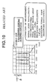
- Fig. 10 shows an output spectrum of the hybrid EDF in cascade connection of P-Al-codoped EDF and Al-doped EDF.
- the Hybrid EDF of Fig. 10 inputs a signal light from the side of P-Al-codoped EDF and inputs a pump light from the side of Al-doped EDF.
- the total input signal light is -15 dBm and the excitation wavelength is 1.47 ⁇ m.
- Fig. 10 shows a slope ⁇ of gain obtained from the output spectrum whose signal light wavelength is 1543, 1548, 1552, and 1558 nm. Each gain is almost the same and the slope ⁇ is close to zero.
- Fig. 11 shows an output spectrum at a simultaneous amplification of four waves (1543/1548/1552/1558 nm) by Al-doped EDF under the same conditions for Fig. 10.
- a slope ⁇ of gain from the output spectral whose signal light wavelength is 1543, 1548, 1552 and 1558 nm is shown.
- Fig. 12 shows an output spectrum at a simultaneous amplification of four waves (1543/1548/1552/1558 nm) by P-Al-codoped EDF under the same conditions of Fig. 10.
- a slope ⁇ of gain from the output spectral whose signal light wavelength is 1543, 1548, 1552 and 1558 nm is shown.
- Fig. 11 the gain of the signal light on the longer wavelength is higher and a maximum of difference of gain between the four waves is about 3dB.
- Fig. 12 by using P-Al-codoped EDF, a contrary amplification characteristic to Al-codoped EDF can be obtained when a wavelength is from 1.54 to 1.56 ⁇ m.
- Fig. 10 shows wavelength dependency of output at the time of a simultaneous amplification of four waves.
- the total output power of the hybrid EDF is + 14.2 dBm, which is almost equal to that of Al-doped EDF of 22 m in length.
- a maximum difference of gain between four waves by hybrid EDF is 1.3 dB and this value (1.3dB) almost corresponds to that of Al-doped EDF of 13 m in length.
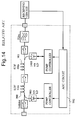
- Fig. 14 shows a configuration of an optical preamplifier.
- the former EDF 900 performs 0.98 ⁇ m (980 nm) forward excitation in order to reduce noise.
- the latter EDF 901 performs 1.48 ⁇ m (1480 nm) backward excitation.
- the former EDF 900 is 12m in length and the back step EDF 901 is 40 m in length.
- An Automatic Gain Control (AGC) circuit 902 controls outputs of a 980 nm Laser Diode (LD) and a 1480nm LD in order to make data amplitude of a receiving circuit stable.
- AGC Automatic Gain Control
- the laser module using the non-spherical lens as shown in Fig. 15 has a case 910 fixing the non-spherical lens 914 inside and a package putting a laser 915 inside.
- the case and the package are fixed by welding and integrated.
- one optical circulator has input/output terminals for the optical amplifier and prevents reversing of lights and has a function for providing a stable amplification operation. Therefore, a simplified configuration can be enabled by using a fewer number of elements.
- an excitation by 0.98 ⁇ m pump light as known, three-level of excitation is enabled, and a low noise characteristic can be realized.
- energy conversion efficiency of a pump light and a signal light is calculated according to ratio of each wavelength of the light.
- the EDF 2a and the EDF 2b as shown in Related Art 1 provides light amplification operation of wavelength range, from about 1.52 to 1.58 ⁇ m.
- amplification rate that is, a gain depends on the wavelength of the signal light.
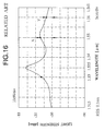
- Fig. 16 shows ASE (Amplified Spontaneous Emission) spectral in erbium-diffused optical fiber where erbium is diffused in pure silica (SiO 2 ) core (Fig. 16 shows a figure on page 115 of "Optical amplifier and its application" published by Ohmu-sya).
- FIG. 16 shows a light strength (hereinafter, referred to as power) to a signal light whose wavelength is from 1.515 ⁇ m to 1.565 ⁇ m according to a 0.98 ⁇ m pump light.
- the power has peaks at the wavelength of 1.536 ⁇ m and 1.552 ⁇ m.
- the power is at least at wavelength of 1.515 ⁇ m in the figure. Then, the difference of the power between the wavelength of 1.536 ⁇ m and that of 1.515 ⁇ m is almost 30dB.
- the present invention is made to solve these and other problems. It is an object of the present invention to obtain an optical amplifier to improve energy conversion efficiency. Further, it is an object of the present invention to obtain an optical amplifier to make the wavelength dependency of gain small. Further, it is an object of the present invention to obtain a small optical amplifier.
- An optical amplifier in the present invention comprises:
- the signal light includes light having different wavelengths and wavelength dependency of gain obtained by amplifying the signal light with the first light amplified fiber and wavelength dependency of gain obtained by amplifying the signal light with the second light amplified fiber are compensated so that gain spectrum is made flat.
- the signal light includes a first signal light and a second signal light having different wavelengths
- the optical amplifier further comprises a third optical filter connected between the second terminal of the optical transmitter and first light amplified fiber for transmitting the first signal light
- the optical amplifier further comprises a fourth optical filter, connected between the third terminal of the optical transmitter and the second light amplified fiber, for passing the second signal light when the third optical filter passes the first signal light.
- An optical transmitter in the present invention comprises:
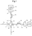
- Fig. 1 shows a configuration of an optical amplifier of the present invention.
- an LD/M 4c is connected to the terminal 1c and is 1.48 ⁇ m band LD/M (LD/M: laser diode module).
- LD/M laser diode module
- the other reference numbers are equivalent to those already described in Fig. 9.
- a pump light whose wavelength of 0.98 ⁇ m is output from an LD/M 4a.
- a pump light whose wavelength is 1.48 ⁇ m is output from an LD/M 4c.
- a pump light whose wavelength is 0.98 ⁇ m realizes a lower noise amplification, compared to a case where light is amplified by a pump light whose wavelength is 1.48 ⁇ m.
- the optical amplifier of the present invention amplifies the signal light according to the EDF 2a by using a pump light whose wavelength is 0.98 ⁇ m.
- the signal light amplified by the EDF 2a is amplified according to the EDF 2b by using a pump light whose wavelength is 1.48 ⁇ m.
- pump light whose wavelength is 1.48 ⁇ m By using pump light whose wavelength is 1.48 ⁇ m, a larger energy conversion efficiency than a case of a pump light whose wavelength is 0.98 ⁇ m can be achieved.
- a basic operation is similar to that of an optical amplifier of Related Art 1.
- An optical amplifier of Fig. 1 is a reflection type of optical amplifier using an optical circulator 1. Therefore, an input signal light goes back and forth in the EDF 2a and the EDF 2b.
- the length of the EDF 2a and the EDF 2b can be halved.
- the signal light goes back and forth between the EDFs. Therefore, the length of the EDF can be made half in order to obtain the same gain.
- the power of the pump light of 0.98 ⁇ m to maintain a low noise characteristic can be less.
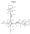
- the EDF 2c and the EDF 2d are different kinds of EDF.
- aluminum oxide Al 2 O 3
- aluminum oxide and phosphorus oxide Al 2 O 3 -P 2 O 3
- the other elements are equivalent to conventional ones of Fig. 9.
- the wavelength of the pump light supplied from the LD/M 4a and the LD/M 4b is assumed to be 0.98 ⁇ m. However, the wavelength supplied from the LD/M 4a and the LD/M 4b can be different from each other.
- the basic operation of the optical amplifier of Fig. 2 is equal to that of Fig. 1.
- the wavelength dependency of gain of the EDF 2c and the EDF 2d is different from each other, as explained with reference to Figs. 11 and 12 in Related Art 2.
- the EDF 2c and the EDF 2d are designed to compensate the wavelength dependency of gain each other for the input signal light.
- the gain is flat, in a case where the signal light of wavelength of a certain range is input, the same gain is given to each signal light.
- the signal light of wavelength of a range from 1543 nm to 1558 nm is input, almost the same gain can be achieved as shown in Fig. 10. Therefore, it is possible not to cause unbalance of the output signal light.
- the optical amplifier of Fig. 2 is a reflection type of optical fiber amplifier and the signal light comes back and forth between the EDF 2c and the EDF 2d.
- the length of P-Al-codoped EDF and Al-doped EDF should be longer than the length of the EDF 2c and the EDF 2d.
- the length of the EDF 2c and the EDF 2d can be shorter than the fiber length of the hybrid optical fiber amplifier of Related Art 2, while obtaining the same gain.
- the shorter the length of the EDF the smaller the wavelength dependency of the gain. That is, the shorter the EDF, the flatter the gain, assuming the pump light power is stable.
- the signal light goes back and forth between the EDF.
- the length of the EDF can be half in order to obtain the same gain. Accordingly, the gain becomes flatter. That is, the wavelength dependency of the gain becomes small.
- the length of the EDF should be adjusted in order to offset the slopes ⁇ (Fig. 11) and ⁇ (Fig. 12) of the different gains provided by the respective EDFs from each other. Since the slope of each EDF in the reflection type of optical amplifier is smaller than that of each EDF in the cascade-connected reflection type of optical amplifier, it is easier to perform length adjustment of the EDF in order to obtain the same flat gain. The easy adjustment brings a better reproductivity of the better flat gain as the result.
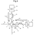
- an optical circulator 1 receives a first signal light L1 and a second signal light L2 having different wavelengths from a terminal 1a.
- a optical filter 3d connected to a terminal 1c reflects the first signal light L1 and passes the second signal light L2. Since to the optical filter 3d passes only the second signal light L2, an EDF 2e connected to the terminal 1c amplifies the second signal light L2.
- the other reference numbers are equivalent to those of Fig. 9 of Related Art 1 and the wavelength of the pump light supplied from the LD/M 4a and the LD/M 4b is assumed to be 0.98 ⁇ m. But, the wavelength of the pump light supplied from the LD/M 4a and the LD/M 4b can be different.
- the optical circulator 1 receives the first signal light L1 and the second signal light L2 of different wavelengths from the terminal 1a.
- the wavelength of the first signal light L1 is assumed to be 1.55 ⁇ m and that of the second signal light L2 is assumed to be 1.56 ⁇ m.
- the wavelength of the first signal light L1 may be 1543 nm and that of the second signal light L2 may be 1552 nm as shown in Fig. 10.
- the signal lights L1 and L2 input from the terminal 1a are amplified by the EDF 2a initially.
- the wavelength of a pump light is assumed to be 0.98 ⁇ m.
- the LD/M 4a of Fig. 3 outputs a pump light of wavelength of 0.98 ⁇ m to the EDF 2a.
- the LD/M 4b of Fig. 3 also outputs a pump light of wavelength of 0.98 ⁇ m to the EDF 2a.
- the gain Y when the signal light whose wavelength is 1.56 ⁇ m is amplified by the EDF 2a, the gain is Y, for example, in a case where the light strength of the signal light of the wavelength of 1.56 ⁇ m is assumed to be - 50dBm.
- the gain X is twice as much as the gain Y.
- the EDF 2e Since the optical filter 3d passes only the second signal light L2, the EDF 2e amplifies only the signal light of 1.56 ⁇ m.
- the signal light of the wavelength of 1.56 ⁇ m is amplified by the gain Y according to each of the EDF 2a and the EDF 2e.
- the gain Y As a result, almost the same gain with that of the signal light of the wavelength of 1.55 ⁇ m can be given. Accordingly, by using an optical amplifier having a configuration of Fig. 3, when the signal light having a different wavelength is input, it is possible to obtain almost the same gain based on the wavelength of the input signal light.
- an optical filter 3d is set between the third terminal, the terminal 1c and the EDF 2e.
- the optical filter 3d can be set between the second terminal, the terminal 1b and the EDF 2a.
- the optical filter 3d passes only the second signal light L2.
- the wavelength of the first signal light L1 is assumed to be 1.55 ⁇ m.
- the wavelength of the second signal light L2 is assumed to be 1.56 ⁇ m.
- the EDF 2a amplifies only the signal light of the wavelength of 1.56 ⁇ m, the second signal light L2.
- the EDF 2e amplifies the signal light of the wavelength of 1.55 ⁇ m, the first signal light L1 and amplifies the signal light of the wavelength of 1.56 ⁇ m amplified by the EDF 2a again. Accordingly, the gain of the first signal light L1 and that of the second signal light L2 are almost the same.
- an optical filter for passing one of the signal lights is set at either of the second terminal or the third terminal.
- the optical circulator 1 of Fig. 4 receives the first signal light L1 and the second signal light L2 from the terminal 1a.
- the first signal light L1 and the second signal light L2 have different wavelengths.
- the optical filter 3c connected to the terminal 1b passes only the first signal light L1.
- the optical filter 3d connected to the terminal 1c passes only the second signal light L2.
- the second signal light L2 input from the terminal 1a is reflected by the optical filter 3c. Accordingly, the second signal light L2 will not be amplified by the EDF 2f. That is, the first signal light L1 input from the terminal 1a is amplified by the EDF 2f passing through the optical filter 3c.
- the second signal light L2 is amplified by the EDF 2g passing through the optical filter 3d.
- the first signal light L1 amplified by the EDF 2f is reflected by the optical filter 3d. Hence, it is not amplified by the EDF 2g.
- the other reference numbers are equivalent to those described in Fig. 9 of Related Arts.
- Both the LD/M 4a and the LD/M 4b supply a pump light having wavelength of 0.98 ⁇ m.
- the LD/M 4a and the LD/M 4b can supply a pump light having a different wavelength from one another.
- the first signal light L1 input from the input terminal 1a gets amplified by the EDF 2c.
- the second signal light L2 gets amplified by the EDF 2e.
- the EDF 2f and the EDF 2g as shown in Fig. 4 are the same kind of the EDF. Since the wavelength of the first signal light L1 and that of the second signal light L2 are different, the gain given to the first signal light L1 and the gain given to the second signal light L2 are different. That is, the gain of the output signal has variation according to the wavelength of the input signal light.
- the kind of the EDF 2f and the EDF 2g it is possible to reduce the variation of the gain caused by the wavelength of the input signal light. For example, by changing the diameter of the core of the EDF 2f and the EDF 2g, it is possible to change the gain. Furthermore, it is possible to change the gain by changing the density of erbium diffusion.
- the diameter of the core of the EDF 2g can be made larger than that of the core of the EDF 2f.
- the EDF 2g can give more gain than the EDF 2f.
- the first signal light L1 whose wavelength is 1.55 ⁇ m and the second signal light L2 whose wavelength is 1.56 ⁇ m are input.
- the gain given by the pump light of 0.98 ⁇ m is X when the wavelength is 1.55 ⁇ m.
- the gain given by the pump light of 0.98 ⁇ m is Y (X>Y).
- the EDF 2f and the EDF 2g are designed so that the gain provided by the EDF 2g becomes more than the gain provided by the EDF 2f. Therefore, it is possible that the gain given to the signal light of the wavelength of 1.56 ⁇ m becomes X.
- the diameter of the core is made large.
- the gain may also be increased by increasing density of erbium diffusion.
- the EDF 2f and the EDF 2g can be the same kind of the EDF.
- the gain by changing the length of the EDF 2f and the EDF 2g.
- the length of the EDF 2g By setting the length of the EDF 2g longer than the length of the EDF 2f, it is possible to increase the gain of the EDF 2g more than that of the EDF 2f.
- the optical filter made of the dielectric multilayered film same with that of Related Art is used as the optical filters 3a, 3b, 3c, and 3d.
- the optical filter is not limited to this.
- Other types of optical filters such as a fiber grating whose core has a diffraction grating, (a periodic distribution of refraction index of fine pitches provided in the core along the axis of the optical fiber is called a fiber grating. (cf. Optical Device Dictionary of Optronics Co., Ltd.)) can be used.
- the optical circulator 11 is an optical circulator having three terminals (or, an optical circulator having four terminals using only three terminals among the four).
- An optical filter 3e is an optical filter made of dielectric multilayered film.
- a package 9 is composed of an optical filter 3e made of dielectric multilayered film, a lens 7 and a laser diode 8 of 0.98 ⁇ m band.
- a light beam 10 shows a transmission path of a pump light.
- a laser module using a non-spherical lens of Fig. 15 described in Related Art 4 does not integrate the optical filter.
- the optical filter made of dielectric multilayered film for reflecting the signal light and having a mechanism of passing the pump light is provided in a light transmission path of the laser diode unit. Then, it is possible to realize a smaller optical amplifier in lighter weight than a conventional optical amplifier using a laser module having a configuration of Fig. 15 of Related Art 4.
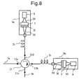
- Fig. 5 an optical circulator having three terminals is described. However, it is possible to couple the package 9 to the optical circulator having four terminals as shown in Fig. 1. At this time, the package 9 is connected as a package 9a and a package 9b, respectively in the EDF 2h and the EDF 2i as shown in Fig. 6.
- Fig. 7 shows an optical amplifier having a configuration as shown in Fig. 6. It has a optical filter 3f on a surface of the lens 7.
- the optical filter 3f is formed on the surface of the lens 7.
- Fig. 7 a case of an optical circulator having three terminals is shown and it is possible to couple the package 9 in the optical circulator having four terminals.
- the package 9 is connected as the package 9a and the package 9b, respectively to the EDF 2h and the EDF 2i as shown in Fig. 8.
- the configurations of the present invention provide an efficient, wavelength independent, small optical amplifier.
Landscapes
- Physics & Mathematics (AREA)
- Electromagnetism (AREA)
- Engineering & Computer Science (AREA)
- Plasma & Fusion (AREA)
- Optics & Photonics (AREA)
- Lasers (AREA)
Applications Claiming Priority (3)
| Application Number | Priority Date | Filing Date | Title |
|---|---|---|---|
| JP35011096 | 1996-12-27 | ||
| JP8350110A JPH10190112A (ja) | 1996-12-27 | 1996-12-27 | 光増幅装置 |
| JP350110/96 | 1996-12-27 |
Publications (2)
| Publication Number | Publication Date |
|---|---|
| EP0851543A2 true EP0851543A2 (fr) | 1998-07-01 |
| EP0851543A3 EP0851543A3 (fr) | 2000-09-27 |
Family
ID=18408307
Family Applications (1)
| Application Number | Title | Priority Date | Filing Date |
|---|---|---|---|
| EP97110307A Withdrawn EP0851543A3 (fr) | 1996-12-27 | 1997-06-23 | Amplificateur optique |
Country Status (3)
| Country | Link |
|---|---|
| US (1) | US5867306A (fr) |
| EP (1) | EP0851543A3 (fr) |
| JP (1) | JPH10190112A (fr) |
Cited By (3)
| Publication number | Priority date | Publication date | Assignee | Title |
|---|---|---|---|---|
| US6429966B1 (en) | 1999-05-19 | 2002-08-06 | Alcatel | Multistage optical amplifier with Raman and EDFA stages |
| EP1168531A3 (fr) * | 2000-06-30 | 2002-10-09 | The Furukawa Electric Co., Ltd. | Amplificateur optique, source lumineuse modulaire et système optique |
| EP0914015A3 (fr) * | 1997-10-28 | 2003-03-12 | Nec Corporation | Commutateur optique, amplificateur optique et commande de puissance optique ainsi que multiplexeur optique a insertion-extraction |
Families Citing this family (21)
| Publication number | Priority date | Publication date | Assignee | Title |
|---|---|---|---|---|
| US5892615A (en) * | 1997-03-17 | 1999-04-06 | Sdl, Inc. | Output power enhancement in optical fiber lasers |
| DE69720450T2 (de) * | 1997-10-07 | 2003-12-24 | Lucent Technologies Inc., Murray Hill | Optische Dispersionskompensation |
| JP3019828B2 (ja) * | 1997-12-02 | 2000-03-13 | 日本電気株式会社 | 双方向光増幅器 |
| US6049418A (en) * | 1998-02-06 | 2000-04-11 | Lucent Technologies, Inc. | Noise figure in optical amplifiers with a split-band architecture |
| JP3264246B2 (ja) * | 1998-03-31 | 2002-03-11 | 日本電気株式会社 | 光増幅器 |
| KR100269177B1 (ko) * | 1998-08-04 | 2000-10-16 | 윤종용 | 장파장 광섬유 증폭기 |
| US6204958B1 (en) * | 1998-10-08 | 2001-03-20 | Ciena Corporation | Optical amplifier having a substantially flat gain spectrum |
| US6377392B1 (en) * | 1999-02-26 | 2002-04-23 | Ciena Corporation | Optical amplifier |
| US6509986B1 (en) * | 1999-02-26 | 2003-01-21 | Ciena Corporation | WDM ring transmission system having amplified dropped channels |
| JP2000354005A (ja) * | 1999-06-11 | 2000-12-19 | Fujitsu Ltd | 利得等化方法、光増幅装置および光伝送システム |
| US6678087B1 (en) * | 1999-08-06 | 2004-01-13 | Nippon Telegraph And Telephone Corporation | Optical amplifier and optical fiber communication system using the amplifier |
| US6507430B2 (en) | 2001-02-23 | 2003-01-14 | Photon X, Inc. | Long wavelength optical amplifier |
| US6731426B2 (en) | 2001-02-23 | 2004-05-04 | Photon-X, Inc. | Long wavelength optical amplifier |
| US6646796B2 (en) * | 2001-05-31 | 2003-11-11 | Samsung Electronics Co., Ltd | Wide band erbium-doped fiber amplifier (EDFA) |
| US6781748B2 (en) | 2001-09-28 | 2004-08-24 | Photon-X, Llc | Long wavelength optical amplifier |
| US20030123141A1 (en) * | 2001-11-19 | 2003-07-03 | Aydin Yeniay | L band optical amplifier |
| KR100414914B1 (ko) * | 2002-03-05 | 2004-01-13 | 삼성전자주식회사 | 이득 향상된 광대역 어븀첨가 광섬유 증폭기 |
| KR100480275B1 (ko) * | 2002-12-09 | 2005-04-07 | 삼성전자주식회사 | 반사형 분산보상 광증폭장치 |
| US6965472B2 (en) * | 2004-03-22 | 2005-11-15 | Raytheon Company | Nonreciprocal optical element with independent control of transmission opposite directions |
| US7106501B2 (en) * | 2004-10-14 | 2006-09-12 | Coherent, Inc. | Fiber amplifier with suppression of amplified spontaneous emission |
| US20240162675A1 (en) * | 2022-11-15 | 2024-05-16 | Ii-Vi Delaware, Inc. | Dual-Band ASE Source Utilizing A Reflective Topology |
Family Cites Families (6)
| Publication number | Priority date | Publication date | Assignee | Title |
|---|---|---|---|---|
| IT1227614B (it) * | 1988-12-22 | 1991-04-22 | Italtel Spa | Modulo ibrido ricetrasmittente per la trasmissione bidirezionale su una fibra ottica monomodale di due segnali ottici |
| JPH06318754A (ja) * | 1993-05-10 | 1994-11-15 | Matsushita Electric Ind Co Ltd | 光ファイバ増幅器および光信号伝送システム |
| JPH06324368A (ja) * | 1993-05-11 | 1994-11-25 | Nippon Telegr & Teleph Corp <Ntt> | 光ファイバ増幅器 |
| US5579143A (en) * | 1993-06-04 | 1996-11-26 | Ciena Corporation | Optical system with tunable in-fiber gratings |
| JPH07297469A (ja) * | 1994-04-28 | 1995-11-10 | Hitachi Cable Ltd | 多段型光ファイバ増幅器及びその光学部品 |
| US5598294A (en) * | 1994-08-18 | 1997-01-28 | Matsushita Electric Industrial Co., Ltd. | Optical fiber amplifier and optical fiber communication system |
-
1996
- 1996-12-27 JP JP8350110A patent/JPH10190112A/ja active Pending
-
1997
- 1997-06-19 US US08/878,816 patent/US5867306A/en not_active Expired - Fee Related
- 1997-06-23 EP EP97110307A patent/EP0851543A3/fr not_active Withdrawn
Cited By (4)
| Publication number | Priority date | Publication date | Assignee | Title |
|---|---|---|---|---|
| EP0914015A3 (fr) * | 1997-10-28 | 2003-03-12 | Nec Corporation | Commutateur optique, amplificateur optique et commande de puissance optique ainsi que multiplexeur optique a insertion-extraction |
| US7197246B2 (en) | 1997-10-28 | 2007-03-27 | Nec Corporation | Optical switch, optical amplifier and optical power controller as well as optical add-drop multiplexer |
| US6429966B1 (en) | 1999-05-19 | 2002-08-06 | Alcatel | Multistage optical amplifier with Raman and EDFA stages |
| EP1168531A3 (fr) * | 2000-06-30 | 2002-10-09 | The Furukawa Electric Co., Ltd. | Amplificateur optique, source lumineuse modulaire et système optique |
Also Published As
| Publication number | Publication date |
|---|---|
| JPH10190112A (ja) | 1998-07-21 |
| US5867306A (en) | 1999-02-02 |
| EP0851543A3 (fr) | 2000-09-27 |
Similar Documents
| Publication | Publication Date | Title |
|---|---|---|
| US5867306A (en) | Optical amplifier | |
| US7480092B2 (en) | Optical amplification method and device usable with bands other than the C-band | |
| CA2150950C (fr) | Amplificateur optique | |
| US6903865B2 (en) | Communication system using S-band Er-doped fiber amplifiers with depressed cladding | |
| US6624927B1 (en) | Raman optical amplifiers | |
| US20030151800A1 (en) | Long-band erbium doped fiber amplifier | |
| US6043930A (en) | Optical amplifier and optical fiber applicable to optical amplifier | |
| US20020003655A1 (en) | L-band optical fiber amplifier | |
| US6665114B2 (en) | Hybrid Raman-erbium optical amplifier | |
| US20040240043A1 (en) | Optical fiber amplifier | |
| US6697393B2 (en) | Laser amplifier, method and apparatus for laser amplification, and laser oscillator | |
| US6384965B2 (en) | Wavelength division multiplexing optical fiber amplifier | |
| HU212954B (en) | Broad band amplifier with optical fiber | |
| US6466363B1 (en) | Broadband amplification with first and second amplifiers having different pump wavelength requirements | |
| US6344924B1 (en) | Optical fiber amplifier and output power flattening method of optical fiber amplifier | |
| US8194309B2 (en) | Optical amplifier using delayed phase matching fiber | |
| US6624928B1 (en) | Raman amplification | |
| US20020089738A1 (en) | Optical fiber amplifier and method of amplifying an optical signal | |
| JPH09138432A (ja) | 光増幅器 | |
| JP4703026B2 (ja) | 広帯域ase光源 | |
| WO2002079851A1 (fr) | Amplificateur a fibre dopee a l'erbium et a gain fixe destine a la bande des ondes longues | |
| US20030138013A1 (en) | Optical fiber amplifier that can attain sufficient gain shift effect, small noise property and high operation efficiency at the same time even in two-wavelength excitation Tm dopant optical fiber amplifier, and optical amplifier having the same | |
| JP2006505117A (ja) | 光増幅器 | |
| US20050190433A1 (en) | Optical fiber and hybrid optical amplifier using the same | |
| JPH10215015A (ja) | 光ファイバ増幅部、光ファイバ増幅器、および光ファイバ増幅器の利得等化方法 |
Legal Events
| Date | Code | Title | Description |
|---|---|---|---|
| PUAI | Public reference made under article 153(3) epc to a published international application that has entered the european phase |
Free format text: ORIGINAL CODE: 0009012 |
|
| AK | Designated contracting states |
Kind code of ref document: A2 Designated state(s): DE FR GB |
|
| PUAL | Search report despatched |
Free format text: ORIGINAL CODE: 0009013 |
|
| AK | Designated contracting states |
Kind code of ref document: A3 Designated state(s): AT BE CH DE DK ES FI FR GB GR IE IT LI LU MC NL PT SE |
|
| AKX | Designation fees paid |
Free format text: DE FR GB |
|
| STAA | Information on the status of an ep patent application or granted ep patent |
Free format text: STATUS: THE APPLICATION IS DEEMED TO BE WITHDRAWN |
|
| 18D | Application deemed to be withdrawn |
Effective date: 20010328 |